Page 244 of 396
FRONT SUSPENSION – On-vehicle Service33A-3
ON-VEHICLE SERVICE
WHEEL ALIGNMENT CHECK AND
ADJUSTMENT
Use the conventional procedures to measure wheel alignment.
1. CAMBER
Standard value:
–1�00’ ± 30’ (difference between right and left
wheel: less than 30’) or
–2�00’ ± 30’ (difference between right and left
wheel: less than 30’)
Select the camber angle as follows.
If the arrow on the bolt that couples the strut assembly
to knuckle faces inboard → –1�00’ ± 30’.
If the arrow on the bolt that couples the strut assembly
to knuckle faces outboard → –2�00’ ± 30’.
2. CASTER
Standard value: 3�54’ ± 30’ (difference between right
and left wheel: less than 30’)
NOTE
The suspension system is designed so as to retain the
preset caster value, requiring no adjustment for caster.
Bolt coupling strut
assembly to
knuckle
Page 245 of 396
FRONT SUSPENSION – Strut Assembly33A-4
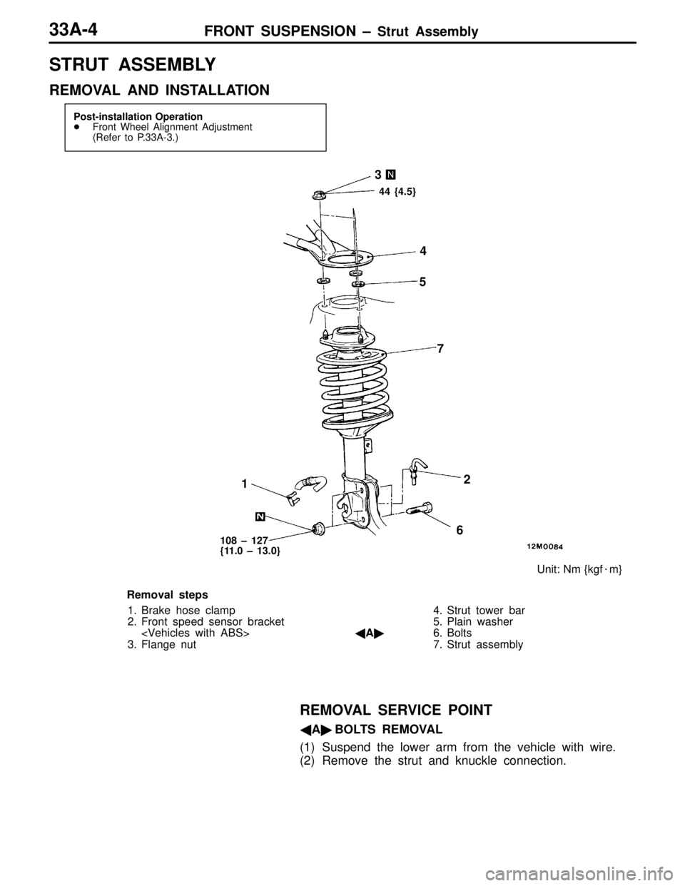
STRUT ASSEMBLY
REMOVAL AND INSTALLATION
Post-installation Operation
�Front Wheel Alignment Adjustment
(Refer to P.33A-3.)
12 3
4
5
6 7
Unit: Nm {kgf�m}
44 {4.5}
108 – 127
{11.0 – 13.0}
Removal steps
1. Brake hose clamp
2. Front speed sensor bracket
3. Flange nut4. Strut tower bar
5. Plain washer
�A�6. Bolts
7. Strut assembly
REMOVAL SERVICE POINT
�A�BOLTS REMOVAL
(1) Suspend the lower arm from the vehicle with wire.
(2) Remove the strut and knuckle connection.
Page 246 of 396
FRONT SUSPENSION – Lower Arm 33A-5
LOWER ARM
REMOVAL AND INSTALLATION
Post-installation Operation
(1) Push the Dust Cover of the Lower Arm and Stabilizer
Link Ball Joint with a Finger to Check for Possible
Cracks or Damage.
(2) Wheel Alignment Check and Adjustment
12
3
45
6
Unit: Nm {kgf�m}
39 {4.0}113 {11.5}
Molybdenum disulfide-base chassis
grease:
SHOWA SHELL SEKIYU SUNLITE
MB2, NISSEKI CLAKNOCK FL, or
equivalent
137 {14.0}
88 {9.0} 106 {10.8}*
6
Removal steps
1. Stabilizer link mounting nut
�A�2. Lower arm to knuckle coupling bolt
3. Bolt
4. Stabilizer bracket
�A�5. Bushing assembly
6. Lower arm assemblyCaution
The part marked with * should be first temporarily
tightened, then torqued to specification with the
vehicle on the ground in unloaded condition.
NOTE
Follow the conventional procedures for removal service
points.
Page 247 of 396
FRONT SUSPENSION – Lower Arm 33A-6
INSTALLATION SERVICE POINT
�A�BUSHING ASSEMBLY INSTALLATION
Install the bushing assembly to the lower arm assembly with
a relative angle as shown and tighten the self-locking nut
to the specified torque.
Tightening torque: 137 Nm {14.0 kgf�m}
INSPECTION
BALL JOINT ROTATION STARTING TORQUE
Use the conventional procedures except the special tool used
and the standard value as given below.
Standard value: 2.0 – 8.8 Nm {20 – 90 kgf�cm}
LOWER ARM BALL JOINT DUST COVER
REPLACEMENT
Replace the dust cover by using the conventional procedure
only if it has been inadvertently damaged during servicing.
After the dust cover has been replaced with a new one, push
it with a finger to check for possible cracks or damage.
Bushing assembly
Lower arm assembly
MB991006
Page 248 of 396
FRONT SUSPENSION – Lower Arm 33A-7
LOWER ARM
REMOVAL AND INSTALLATION
Caution
To prevent bushing from being galled, the part
marked with * should be first temporarily tightened,
then torqued to specification with the vehicle on
the ground in unloaded condition.Post-installation Operation
(1) Push the Dust Cover of the Lower Arm and Stabilizer
Link Ball Joint with a Finger to Check for Possible
Cracks or Damage.
(2) Wheel Alignment Check and Adjustment
(Refer to P.33A-3.)
12
3
456
Unit: Nm {kgf�m} Molybdenum disulfide-base chassis
grease:
SHOWA SHELL SEKIYU SUNLITE
MB2, NISSEKI CLAKNOCK FL, or
equivalent
39 {4.0}108 {11.0}
137 {14.0}
88 {9.0} 106 {10.8}*
6
Removal steps
1. Stabilizer link mounting nut
�A��B�2. Lower arm to knuckle coupling bolt
3. Bolt
4. Stabilizer bracket
�A�5. Bushing assembly
6. Lower arm assemblyNOTE
Follow the conventional procedures for removal service
points.
Page 249 of 396
")
FRONT SUSPENSION – Lower Arm 33A-8
INSTALLATION SERVICE POINTS
�A�BUSHING ASSEMBLY INSTALLATION
Follow the conventional procedure.
�B�LOWER ARM TO KNUCKLE COUPLING BOLT
INSTALLATION
(1) Install the lower arm assembly to the knuckle.
Caution
To prevent the dust cover lip from being recessed
and grease from flowing out, ensure that protrusion
A of the ball joint stud from knuckle measures 4 mm
or less during installation of the lower arm assembly.
(2) Should the knuckle be pushed in excessively and grease
flow out from the dust cover, replace the dust cover with
a new one.
(3) Check that there is no clearance between the knuckle
and dust cover.
INSPECTION
BALL JOINT ROTATION STARTING TORQUE
Use the conventional procedures.
LOWER ARM BALL JOINT DUST COVER
REPLACEMENT
Replace the dust cover by using the conventional procedure
if it has been inadvertently damaged or grease flown out
during servicing.
After the dust cover has been replaced with a new one, push
it with a finger to check for possible cracks or damage.
Knuckle
Lower arm
assembly
Page 250 of 396
FRONT SUSPENSION – Stabilizer Bar33A-9
STABILIZER BAR
REMOVAL AND INSTALLATION
Pre-removal Operation
�Crossmember RemovalPost-installation Operation
(1) Crossmember Installation
(2) Check the Stabilizer Link Ball Joint Dust Cover for
Cracks or Damage by Pushing it with Finger.
1
23
4
5
Unit: Nm {kgf�m}
22 {2.2}
SHOWA SHELL SEKIYU
VARIANT R-2 or equivalent
39 {4.0}
39 {4.0}
1
Removal steps
1. Stabilizer link
2. Stabilizer bar bracket
�A�3. Fixture
�A�4. Bushing
5. Stabilizer bar
INSTALLATION SERVICE POINT
�A�FIXTURE / BUSHING INSTALLATION
Install the stabilizer bar so that the identification mark is
positioned at left. Fit the bushing so that the mark may protrude
about 10 mm from the inner end of the bushing, then secure
it with the fixture.Approx. 10 mm
Page 252 of 396
34-1
REAR
SUSPENSION
CONTENTS
SERVICE SPECIFICATIONS 2. . . . . . . . . . . . . .
LUBRICANT 2. . . . . . . . . . . . . . . . . . . . . . . . . . . . .
SPECIAL TOOLS 2. . . . . . . . . . . . . . . . . . . . . . . .
ON-VEHICLE SERVICE 3. . . . . . . . . . . . . . . . . .
1. Rear Wheel Alignment Check and
Adjustment 3. . . . . . . . . . . . . . . . . . . . . . . . . . .
2. Ball Joint Dust Cover Check 3. . . . . . . . . . .
REAR SUSPENSION ASSEMBLY 4. . . . . . . . . UPPER ARM ASSEMBLY 6. . . . . . . . . . . . . . . .
TRAILING ARM ASSEMBLY 8. . . . . . . . . . . . . .
LOWER ARM AND TOE CONTROL
ARM ASSEMBLIES 10. . . . . . . . . . . . . . . . . . . .
SHOCK ABSORBER ASSEMBLY 13. . . . . . .
STABILIZER BAR 14. . . . . . . . . . . . . . . . . . . . . .

 Push the Dust Cover of the Lower Arm and Stabilizer
Link Ball Joint")