Page 2 of 170

ICONS
Indicates a warning. Read the
following section onWarningsfor a
full explanation.
Indicates vehicle information related
to recycling and other
environmental concerns will follow.
Correct vehicle usage and the
authorized disposal of waste
cleaning and lubrication materials
are significant steps towards
protecting the environment.
WARNINGS
Warnings provide information which may reduce the risk of personal
injury and prevent possible damage to others, your vehicle and its
equipment.
BREAKING-IN YOUR VEHICLE
There are no particular breaking-in rules for your vehicle. During the
first 1 600 km (1 000 miles) of driving, vary speeds frequently. This is
necessary to give the moving parts a chance to break in.
If possible, you should avoid full use of the brakes for the first 1 600 km
(1 000 miles).
INFORMATION ABOUT THIS GUIDE
The information found in this guide was in effect at the time of printing.
Ford may change the contents without notice and without incurring
obligation.
Introduction
2
Page 15 of 170
²OIL CHANGE RESET. This
feature allows you to reset the oil
monitoring system to 100 percent
after each oil change. To reset,
the RESET control must be
pressed and held for 5 seconds
while the display counts down.
After a successful reset, the
message center will display ªOIL
LIFE RESET TO 100%.º To
ensure accurate oil life indicators,
perform the reset procedure only
after an oil change.
You can also set a personalized oil reset percentage, which allows you to
establish a smaller oil change interval.
1. Press and hold the RESET control from the VEHICLE SETTINGS
menu OIL CHANGE RESET screen.
2. While holding the RESET control
as the display counts down the
seconds to an oil change reset, press
the VEHICLE SETTINGS control.
The display will read START OIL
LIFE AT XXX%, where XXX is the
currently selected oil life
percentage. Release both controls.
RESET
N
S W
E DATE
TIMESYSTEM
CHECK
VEHICLE
SETTINGDRIVER
SETTINGTRIP
ODO RANGE
FUELECONOMY
Instrumentation
16
Page 16 of 170
3. Press the RESET control to
obtain the desired personalized oil
change percentage. Your choices are
100%, 90%, 80%, 70%, 60%, 50%,
40% and 30%.
4. Press the VEHICLE SETTING
control to complete the procedure.
A press of any control other than
RESET or VEHICLE SETTING will
abort the procedure and will not
establish a new personalized oil
reset percentage.
Your personalized oil change
percentage will begin upon
completion of your next OIL
CHANGE RESET procedure. Refer
toCHANGE OIL SOON/OIL
CHANGE REQUIREDfor more information.
Driver setting menu
The DRIVER SETTING menu allows
you to cycle through seven (if
equipped with phone) features,
saved for each driver personality
profile. These features can be
turned on or off by pressing the
RESET control.
RESET
N
S W
E DATE
TIMESYSTEM
CHECK
VEHICLE
SETTINGDRIVER
SETTINGTRIP
ODO RANGE
FUELECONOMY
VEHICLE
SETTINGDRIVER
SETTINGTRIP
ODO RANGE
FUELECONOMY
Instrumentation
17
Page 30 of 170

2. Press the RESET switch and hold
it down for five seconds while the
display counts down to trigger an oil
change reset.
3. After a successful reset, the
message center will display OIL
LIFE RESET TO 100% (if you have
established a personalized oil reset
percentage, the display will instead
show that percentage).
To ensure accurate oil life
indicators, perform this reset
procedure only after an oil change.
GEAR DISPLAY DATA ERR. Displayed when the data used to provide
the redundant gear selection display on the instrument cluster is missing
or invalid. In this case, the instrument cluster redundant gear selection
display is turned off. The driver should use the mechanical position
indication on the center console gear selector as temporary indication. If
this warning stays on, contact your dealer as soon as safely possible.
Function/status error messages
A function/status error message may be displayed by the message center
instead of a warning or requested function if the information is not
currently available because of:
²improper operation of sensor systems
²the vehicle network communication between electronic modules
Error messages have two formats:
²DATA ERROR or DATA ERR. These messages indicate improper
operation of the vehicle network communication between electronics
modules. Contact your dealer as soon as safely possible if these
messages occur on a regular basis.
²SENSOR OPEN or SENSOR SHORT. These messages indicate
improper operation of vehicle sensor systems or vehicle
wiring/connectors between the sensors and the message center.
Contact your dealer as soon as safely possible if these messages occur
on a regular basis.
RESET
N
S W
E DATE
TIMESYSTEM
CHECK
Instrumentation
31
Page 35 of 170

For continuous maximum heating, push the red button until 32ÉC (90ÉF)
is shown in the display window. The EATC will continue maximum
heating (disregarding the displayed temperature) until a cooler
temperature is selected by pressing the blue button.
Temperature conversion
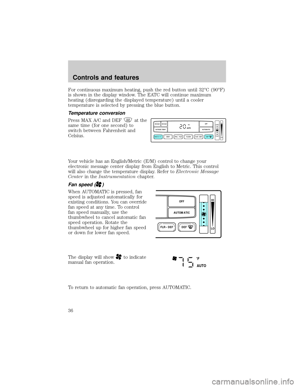
Press MAX A/C and DEFat the
same time (for one second) to
switch between Fahrenheit and
Celsius.
Your vehicle has an English/Metric (E/M) control to change your
electronic message center display from English to Metric. This control
will also change the temperature display. Refer toElectronic Message
Centerin theInstrumentationchapter.
Fan speed ()
When AUTOMATIC is pressed, fan
speed is adjusted automatically for
existing conditions. You can override
fan speed at any time. To control
fan speed manually, use the
thumbwheel to cancel automatic fan
speed operation. Rotate the
thumbwheel up for higher fan speed
or down for lower fan speed.
The display will show
to indicate
manual fan operation.
To return to automatic fan operation, press AUTOMATIC.
VENT PNL • FLR FLOOR FLR • DEF DEF
HI
LO
MAX A/C
OUTSIDE TEMP AUTOMATICOFFAUTO
FLR • DEFDEF
HI
LO
AUTOMATICOFF
˚F
AUTO
Controls and features
36
Page 37 of 170

²FLOOR-Allows for maximum heating by distributing outside air
through the floor ducts. However, the air cannot be cooled below the
outside temperature because the air conditioning does not operate in
this mode.
²FLR²DEF-Distributes outside air through the windshield defroster
ducts and the floor ducts. Heating and air conditioning capabilities are
provided in this mode. The air will be heated or cooled based on the
temperature selection. For added customer comfort, the air
distributed through the floor ducts will be slightly warmer than the air
sent to the windshield defroster ducts. If the temperature is about
10ÉC (50ÉF) or higher, the air conditioner will automatically
dehumidify the air to prevent fogging.
²DEF
-Distributes outside air through the windshield defroster
ducts. It can be used to clear ice or fog from the windshield. If the
outside air temperature is about 10ÉC (50ÉF) or higher, the air
conditioner will automatically dehumidify the air to prevent fogging.
²OFF-Outside air is shut out and the fan will not operate. For short
periods of time only, use this mode to prevent undesirable odors from
entering the vehicle.
Displaying outside temperature
Press OUTSIDE TEMP to display
the outside air temperature. It will
be displayed for four seconds.
If a manual override function is selected while the outside temperature is
displayed, the new function will be displayed for four seconds after it is
changed, then the outside temperature will return to the window along
with the override selection.
The outside temperature reading is most accurate when the vehicle is
moving. Higher readings may be obtained when the vehicle is not
VENTPNL • FLRMAX A/C
OUTSIDE TEMP
Controls and features
38
Page 91 of 170
Guarding against exhaust fumes
Although odorless and colorless, carbon monoxide is present in exhaust
fumes. Take precautions to avoid its dangerous effects.
If you ever smell exhaust fumes of any kind inside your vehicle,
have your dealer inspect and fix your vehicle immediately. Do
not drive if you smell exhaust fumes. These fumes are harmful and
could kill you.
Have the exhaust and body ventilation systems checked whenever:
²the vehicle is raised for service.
²the sound of the exhaust system changes.
²the vehicle has been damaged in a collision.
Important ventilating information
If the engine is idling while the vehicle is stopped in an open area for
long periods of time, open the windows at least 2.5 cm (one inch).
Adjust the heating or air conditioning (if equipped) to bring in fresh air.
Improve vehicle ventilation by
keeping all air inlet vents clear of
snow, leaves and other debris.
Starting
92
Page 113 of 170

The high-current fuses are coded as follows.
Fuse/Relay
LocationFuse Amp
RatingDescription
1 10A* Powertrain Control Module (Keep-Alive
Memory)
2 15A* High Beam Relay, Daytime Running Lamps
Module
3 10A* Powertrain Control Module (EAM Pump
Motor-Monitor)
4 15A* Air Suspension, Electronically Variable
Orifice Power Steering
5 30A* Trunk Lid Relay, Fuel Filler Door Release
6 10A* Air Bag Module
7 Ð Not Used
8 20A* Horn Relay
9 Ð Not Used
10 20A* Radio Amplifier, CD Changer
11 Ð Not Used
12 15A* Steering Column/Ignition/Lighting Module
(Tilt/Telescoping Steering Column Motors,
Mirror Lamps, Brake Shift Interlock, High
Beam Indicator, Anti-Theft Indicator)
13 60A** Air Suspension
14 30A** Delayed Accessory Power Relay #1, I/P
Fuses (4, 10, 16)
15 30A** Powertrain Control Module, PCM Power
Relay, Engine Compartment Fuse 1
16 20A** Fuel Pump Relay, Fuel Pump Module
17 30A** Electronic Air Management, Engine
Compartment Fuse 3
18 30A** Passenger Seat Module, Passenger Lumbar,
I/P Fuse 12
19 30A** Driver Seat Module, Driver Lumbar, I/P
Fuse 35
Roadside emergencies
114