Page 880 of 2490
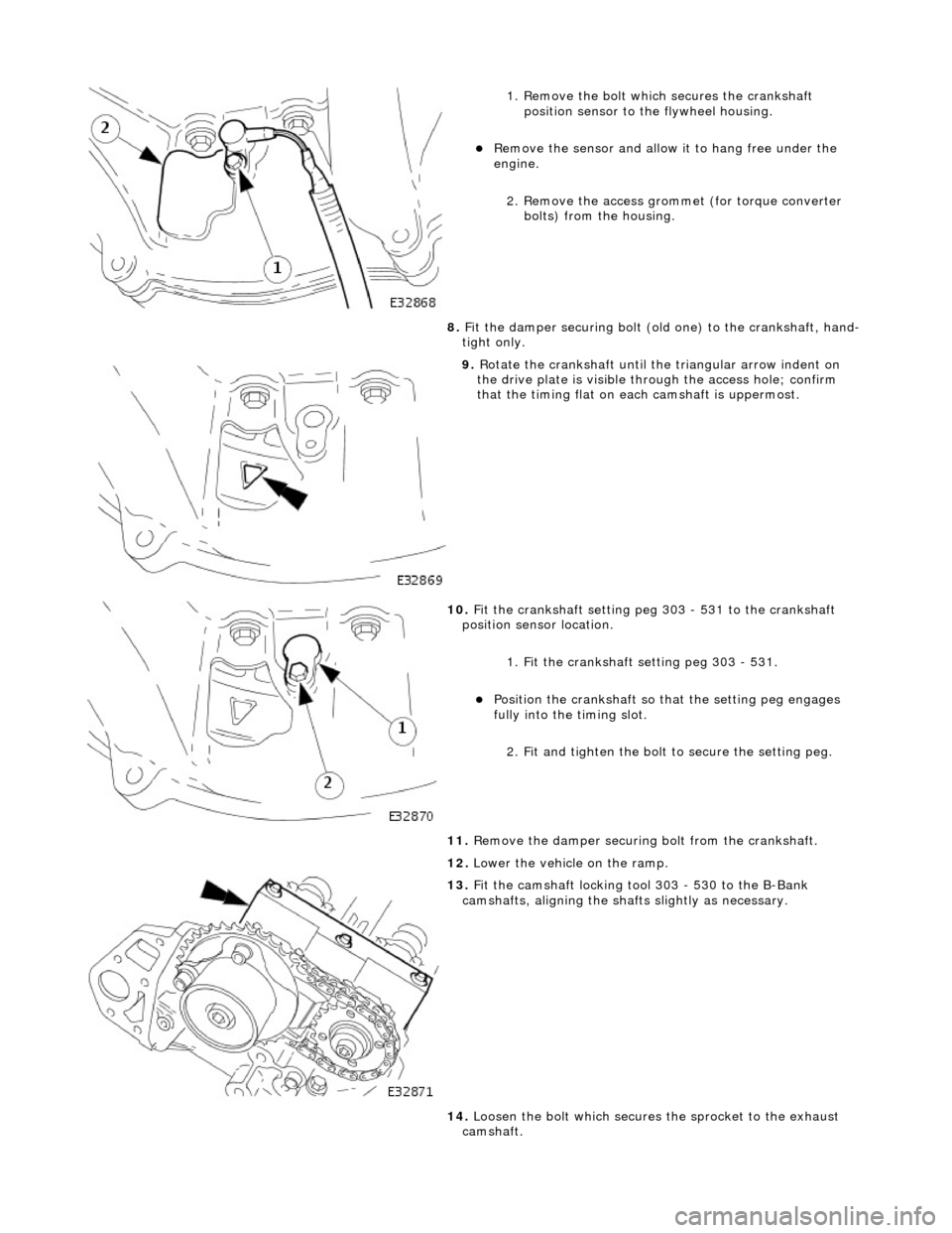
1. Remove the bolt which secures the crankshaft position sensor to the flywheel housing.
Remove the sensor and allow it to hang free under the
engine.
2. Remove the access grommet (for torque converter bolts) from the housing.
8. Fit the damper securing bolt (old one) to the crankshaft, hand-
tight only.
9. Rotate the crankshaft until the triangular arrow indent on
the drive plate is visible thro ugh the access hole; confirm
that the timing flat on ea ch camshaft is uppermost.
10. Fit the crankshaft setting peg 303 - 531 to the crankshaft
position sensor location.
1. Fit the crankshaft setting peg 303 - 531.
Position the crankshaft so that the setting peg engages
fully into the timing slot.
2. Fit and tighten the bolt to secure the setting peg.
11. Remove the damper securing bolt from the crankshaft.
12. Lower the vehicle on the ramp.
13. Fit the camshaft locking tool 303 - 530 to the B-Bank
camshafts, aligning the shafts slightly as necessary.
14. Loosen the bolt which secures the sprocket to the exhaust
camshaft.
Page 883 of 2490
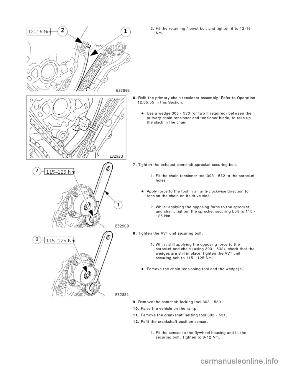
2. Fit the retaining / pivot bolt and tighten it to 12-16 Nm.
6. Refit the primary chain tensione r assembly. Refer to Operation
12.65.55 in this Section.
Use a wedge 303 - 533 (or two if required) between the
primary chain tensioner and te nsioner blade, to take up
the slack in the chain.
7. Tighten the exhaust camshaft sprocket securing bolt.
1. Fit the chain tensioner tool 303 - 532 to the sprocket holes.
Apply force to the tool in an anti-clockwise direction to
tension the chain on its drive side.
2. Whilst applying the opposing force to the sprocket and chain, tighten the sprock et securing bolt to 115 -
125 Nm.
8. Tighten the VVT unit securing bolt.
1. Whilst still applying the opposing force to the
sprocket and chain (using 303 - 532), check that the
wedges are still in place, tighten the VVT unit
securing bolt to 115 - 125 Nm.
Remove the chain tensioning tool and the wedge(s).
9. Remove the camshaft locking tool 303 - 530 .
10. Raise the vehicle on the ramp.
11. Remove the crankshaft setting tool 303 - 531.
12. Refit the crankshaft position sensor.
1. Fit the sensor to the fl ywheel housing and fit the
securing bolt. Tighten to 8-12 Nm.
Page 885 of 2490
Engine - Variable Camshaft Timing Oil Control Unit RH
In-vehicle Repair
Removal
Special Tool(s)
Camshaft setting
303-530
Timing chain tensioning
303-532
Wedges, primary chain
303-533
Crankshaft setting
303-531
1. Open the engine compartment and fit paintwork protection
sheets.
2. Set the engine compartment cover to the service access
position.
3. Disconnect the batt ery ground cable.
Remove the battery cover.
4. Remove the Timing Co ver. Refer to Operation 12.65.01 in this
Section.
5. Remove the Variable Valve Ti ming Bush Carrier Assembly.
Refer to Operation 12.65.51 in this Section
6. Raise the vehicle on a ramp.
7. Remove the crankshaft position sensor.
Page 886 of 2490
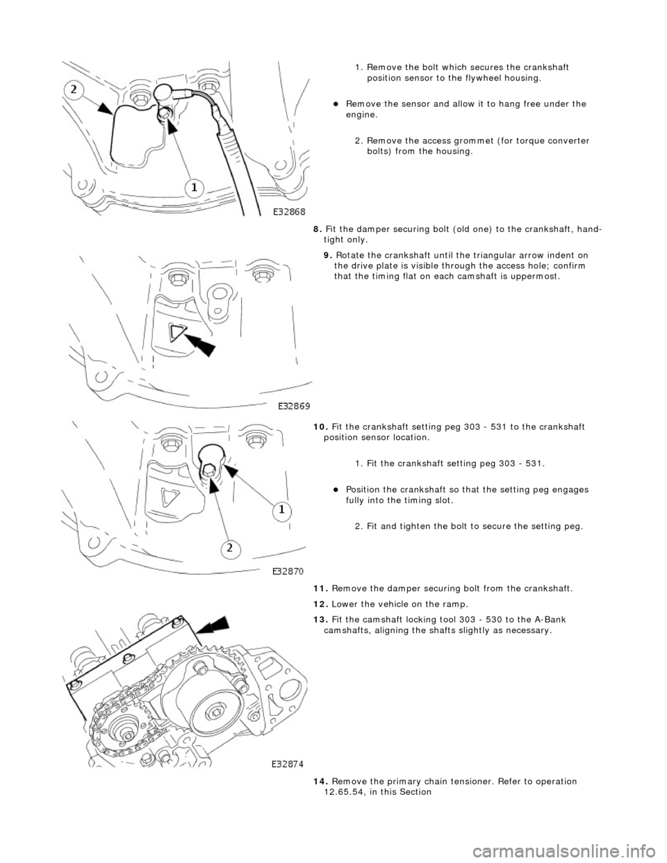
1. Remove the bolt which secures the crankshaft position sensor to the flywheel housing.
Remove the sensor and allow it to hang free under the
engine.
2. Remove the access grommet (for torque converter bolts) from the housing.
8. Fit the damper securing bolt (old one) to the crankshaft, hand-
tight only.
9. Rotate the crankshaft until the triangular arrow indent on
the drive plate is visible thro ugh the access hole; confirm
that the timing flat on ea ch camshaft is uppermost.
10. Fit the crankshaft setting peg 303 - 531 to the crankshaft
position sensor location.
1. Fit the crankshaft setting peg 303 - 531.
Position the crankshaft so that the setting peg engages
fully into the timing slot.
2. Fit and tighten the bolt to secure the setting peg.
11. Remove the damper securing bolt from the crankshaft.
12. Lower the vehicle on the ramp.
13. Fit the camshaft locking tool 303 - 530 to the A-Bank
camshafts, aligning the shafts slightly as necessary.
14. Remove the primary chain tens ioner. Refer to operation
12.65.54, in this Section
Page 889 of 2490
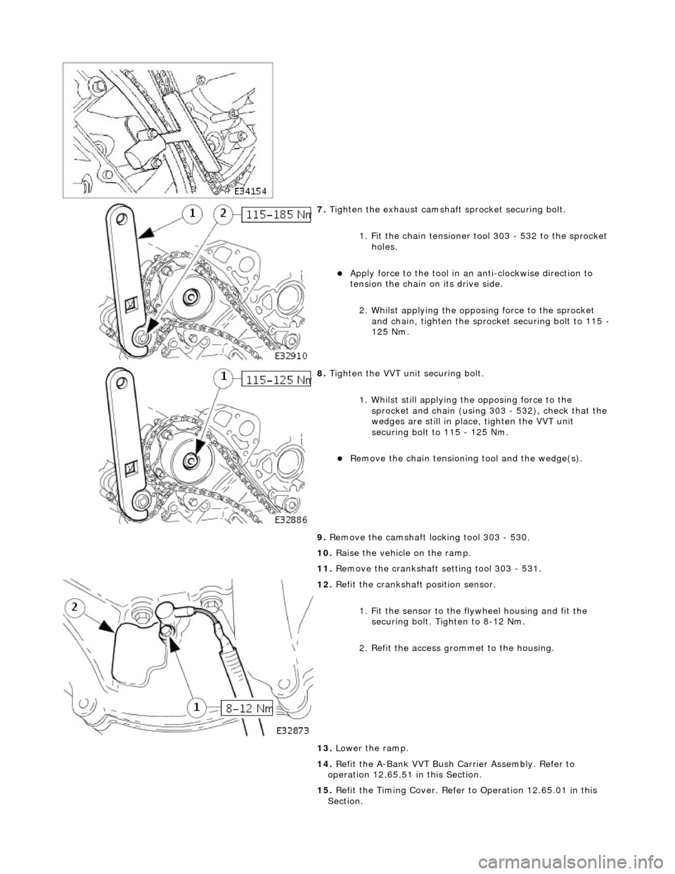
7. Tighten the exhaust camshaft sprocket securing bolt.
1. Fit the chain tensioner tool 303 - 532 to the sprocket holes.
Apply force to the tool in an anti-clockwise direction to
tension the chain on its drive side.
2. Whilst applying the opposing force to the sprocket and chain, tighten the sprock et securing bolt to 115 -
125 Nm.
8. Tighten the VVT unit securing bolt.
1. Whilst still applying the opposing force to the
sprocket and chain (using 303 - 532), check that the
wedges are still in place, tighten the VVT unit
securing bolt to 115 - 125 Nm.
Remove the chain tensioning tool and the wedge(s).
9. Remove the camshaft locking tool 303 - 530.
10. Raise the vehicle on the ramp.
11. Remove the crankshaft setting tool 303 - 531.
12. Refit the crankshaft position sensor.
1. Fit the sensor to the fl ywheel housing and fit the
securing bolt. Tighten to 8-12 Nm.
2. Refit the access grommet to the housing.
13. Lower the ramp.
14. Refit the A-Bank VVT Bush Carrier Assembly. Refer to
operation 12.65.51 in this Section.
15. Refit the Timing Cover. Refer to Operation 12.65.01 in this
Section.
Page 1063 of 2490
Th
e starter drive plate is attached to the rear of the crankshaft by eight bolts.
Timing Disc
A timing disc, for the engine speed sensor, is spot-w elded to the front face of the starter drive plate.
Starter Drive Plate
Page 1179 of 2490
generates a signal when th
e dr
ive plate passes the sensor
sen
ds the ECM signals indicating crankshaft position and engine speed
is e
ssential for calculating spark timing
En
gine Coolant Temperature (ECT) Sensor
sen
ds the ECM a signal indicating the temperature of the engine coolant
is a t
emperature dependent resistor with a negative temperature coefficient (resistance changes inversely with
respect to temperature) and is constantly monitored by the ECM
Intake Air Temperature (IAT) Sensor
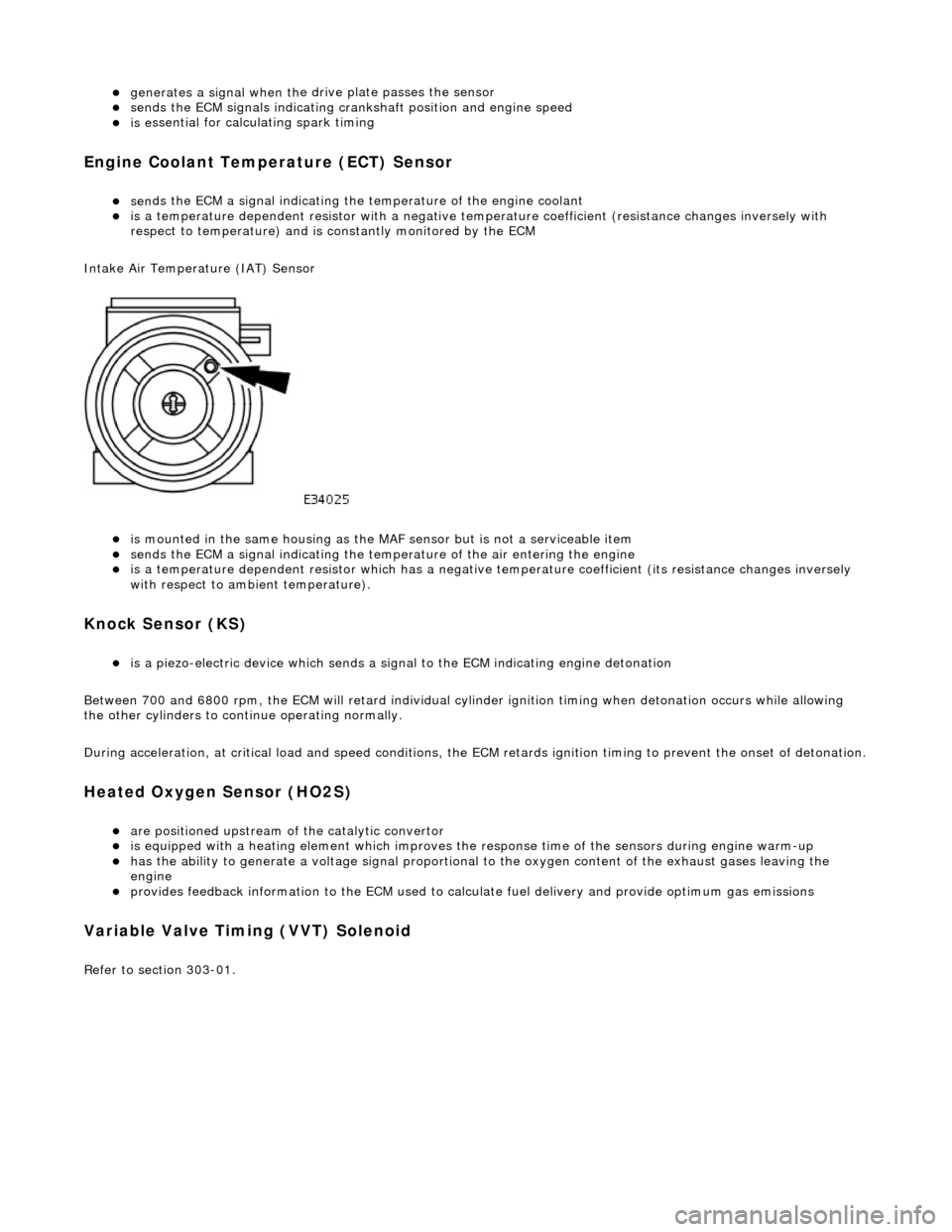
is m
ounted in the same housing as the MA
F sensor but is not a serviceable item
sen
ds the ECM a signal indicating the temperature of the air entering the engine
is a t
emperature dependent resistor which has a negative
temperature coefficient (its resistance changes inversely
with respect to ambient temperature).
Knock S
ensor (KS)
is a pi
ezo-electric device which sends a signal
to the ECM indicating engine detonation
Between 700 and 6800 rpm, the ECM will retard individual cylinder ignition timing when detonation occurs while allowing
the other cylinders to continue operating normally.
During acceleration, at critical load and speed conditions, the ECM retards ignition timing to prevent the onset of detonation.
H
eated Oxygen Sensor (HO2S)
are
positioned upstream of the catalytic convertor
is equipped with
a heating element wh
ich improves the response time of the sensors during engine warm-up
h
as the ability to generate a voltage signal proportional to the oxygen content of the exhaust gases leaving the
engine
pr
ovides feedback information to the ECM used to calc
ulate fuel delivery and provide optimum gas emissions
Variable V
alve Timing (VVT) Solenoid
R
efer to section 303-01.
Page 1185 of 2490
It
em
Par
t Number
De
scription
1—Cranksh
aft position sensor
2—Engine
control module (ECM)
Crankshaft Posi
tion sensor