Page 1054 of 2490

Accessory Drive - Accessory Drive Belt
4.0L SC V8 - AJ26
Re
mo
val and Installation
Remov
a
l
Installation
1.
Op
en the engine compartment and fit paintwork protection
sheets.
2. Remove the supercharger driv e belt, for access. Refer to
operation 18.50.08.
3. Check the belt wear indicator ma rks to confirm that the drive
belt is / is not within limits.
4. CAUTIO
N: When releasing the
belt tension, never apply
any torque in a clockwise direction to the pulley ce ntre bolt (left
hand thread) as it could subsequently loosen.
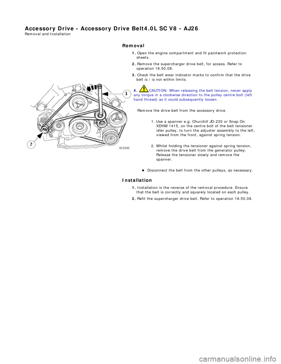
Remove the drive belt fro m the accessory drive.
1. Use a spanner e.g. Churchill JD-230 or Snap On XDHM 1415, on the centre bo lt of the belt tensioner
idler pulley, to turn the adju ster assembly to the left,
viewed from the front, against spring tension.
2. Whilst holding the tensioner against spring tension, remove the drive belt from the generator pulley.
Release the tensioner sl owly and remove the
spanner.
D i
sconnect the belt from the ot
her pulleys, as necessary.
1. Ins
tallation is the
reverse of the remova l procedure. Ensure
that the belt is correctly and sq uarely located on each pulley.
2. Refit the supercharger drive belt. Refer to operation 18.50.08.
Page 1055 of 2490
Accessory Drive - Acce
ssory
Drive Belt Idler Pulley4.0L NA V8 - AJ27/3.2L
NA V8 - AJ26
Re
moval and Installation
I
nstallation
1.
O
pen the engine compartment and fit paintwork protection
sheets.
2. Remove the drive belt for access. Refer to Operation
(12.10.40)
3. R
emove the idler pulley.
1. Remove the securing bolt from the idler pulley.
2. Remove the idler pulley.
1. Installation is the reverse of the removal procedure. Tighten
the pulley securing bolt to 53-69 Nm. Ensure that the belt is
correctly and squarely lo cated on each pulley.
Page 1056 of 2490
Accessory Drive - Accessory Drive Belt
Idler Pulley4.0L SC V8 - AJ26
Re
mo
val and Installation
I
n
stallation
1.
Op
en the engine compartment and fit paintwork protection
sheets.
2. Remove the supercharger driv e belt, for access. Refer to
operation 18.50.08.
3. Remove the accessory drive belt for access. Refer to Operation
(12.10.40)
4. Re
move the idler pulley.
1. Remove the securing bolt from the idler pulley.
2. Remove the idler pulley.
1. Installation is the reverse of the removal procedure. Tighten
the pulley securing bolt to 53-69 Nm. Ensure that the belt is
correctly and squarely lo cated on each pulley.
2. Refit the supercharger drive belt. Refer to operation 18.50.08.
Page 1060 of 2490
Access
ory Drive - Supercharger Belt Idler Pulley
Re
mo
val and Installation
Remov
a
l
Installation
1.
Re
move supercharger drive belt; refer to 18.50.08.
2. Re
move supercharger drive belt idler pulley.
Re
mo
ve bolt .
R
e
move idler pulley.
1. Installation
is a reversal
of the removal procedure.
Page 1106 of 2490
Intake Air Distribution and Filtering -
Torque Specificat
ions
Comp
onent
Nm
Thr
o
ttle intake elbow to intake manifold
18
-
24
Thro
tt
le body to throttle intake elbow
18
-
24
Left-hand support
bracket to
th
rottle intake elbow
16
-
20
Right-hand support
bracket to
throttle intake elbow
16
-
20
B
l
anking plate to throttle intake elbow
18
-
24
Inta
k
e manifold to engine
20
-
22
Supe
rcharger
drive belt idler pulley bolt
34
-
46
Supercharger
drive belt te
nsioner to alternator mounting bracket bolt
39
-
51
Supercharger
to eng
ine bolts
18
-
24
Charge air cooler in
let assembly to charge ai
r cooler bolts
18
-
24
Supercharger
outlet duct to supercharger bolts9-1
1
Charge air cooler in
let assembly to superchar
ger ou
tlet duct bolts
18-
24
Charge air cool
er to charge
air cooler adaptor
11
-
13
B
y
-pass valve to throttle intake elbow
8-
1
2
Page 1890 of 2490

Generator and Regulator - Generator4.0L NA V8 - AJ27/3.2L NA V8 - AJ26
Removal and Installation
Removal
1. Disconnect the batt ery ground cable.
Remove the battery cover.
2. Remove the air cleaner assembly (including fit body paintwork
protection sheets to the adja cent working area); refer to
operation 19.10.05.
3. Remove the twin fan and moto r assembly from behind the
radiator; refer to operation 26.25.12.
4. Check that the belt wear indicator is within the limit marks.
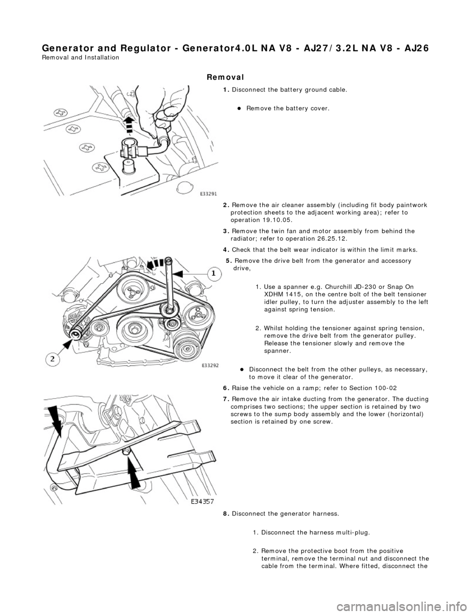
5. Remove the drive belt from the generator and accessory
drive,
1. Use a spanner e.g. Churchill JD-230 or Snap On XDHM 1415, on the centre bo lt of the belt tensioner
idler pulley, to turn the adju ster assembly to the left
against spring tension.
2. Whilst holding the tensioner against spring tension, remove the drive belt from the generator pulley.
Release the tensioner sl owly and remove the
spanner.
Disconnect the belt from the ot her pulleys, as necessary,
to move it clear of the generator.
6. Raise the vehicle on a ramp; refer to Section 100-02
7. Remove the air intake ducting fr om the generator. The ducting
comprises two sections; the upper section is retained by two
screws to the sump body assembly and the lower (horizontal)
section is retained by one screw.
8. Disconnect the generator harness.
1. Disconnect the harness multi-plug.
2. Remove the protective boot from the positive
terminal, remove the termin al nut and disconnect the
cable from the terminal. Where fitted, disconnect the
Page 1893 of 2490

2. Secure the suppression module positive cable and
main positive cable to the generator positive
terminal.
3. Fit the boot to the terminal.
4. Reconnect the generator harness multi-plug.
4. Refit the air intake ducting to the generator. The upper section
is retained by two screws to the sump body assembly and the
lower (horizontal) section is retained by one screw.
5. Lower the vehicle on the ramp ; refer to Section 100-02.
6. Fully tighten the generator upper mounting bolt, to 18-24 Nm.
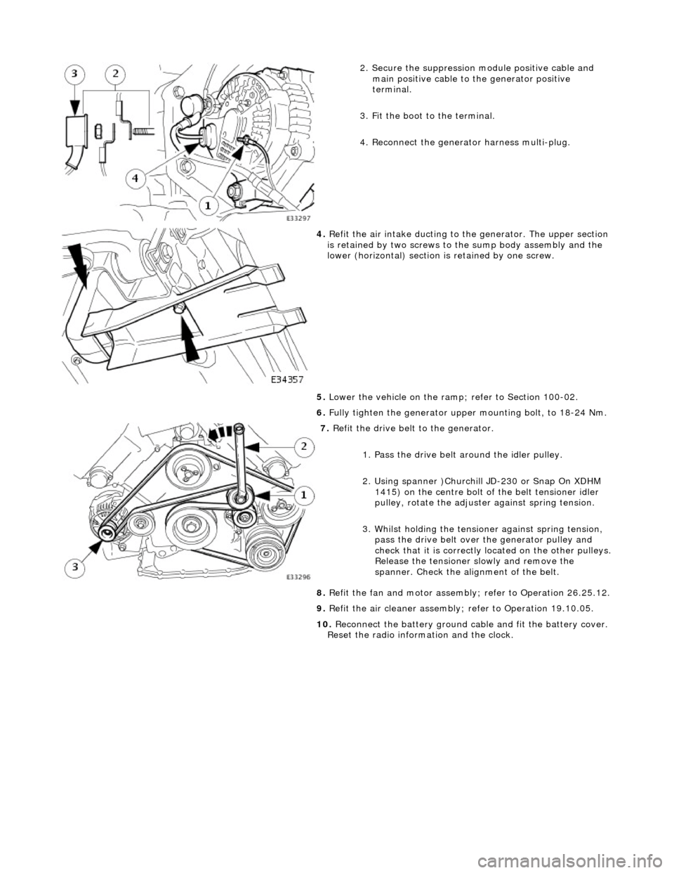
7. Refit the drive belt to the generator.
1. Pass the drive belt around the idler pulley.
2. Using spanner )Churchill JD-230 or Snap On XDHM 1415) on the centre bolt of the belt tensioner idler
pulley, rotate the adjuster against spring tension.
3. Whilst holding the tensioner against spring tension, pass the drive belt over the generator pulley and
check that it is correctly located on the other pulleys.
Release the tensioner slowly and remove the
spanner. Check the alignment of the belt.
8. Refit the fan and motor assembly ; refer to Operation 26.25.12.
9. Refit the air cleaner assembly; refer to Operation 19.10.05.
10. Reconnect the battery ground cable and fit the battery cover.
Reset the radio inform ation and the clock.
Page 1894 of 2490

Generator and Regulator - Generator4.0L SC V8 - AJ26
Removal and Installation
Removal
1. Disconnect the batt ery ground cable.
Remove the battery cover.
2. Remove the air cleaner assembly (including fit body paintwork
protection sheets to the adja cent working area); refer to
operation 19.10.05.
3. Remove the twin fan and moto r assembly from behind the
radiator; refer to operation 26.25.12.
4. Remove the supercharger drive belt; refer to operation
18.50.08.
5. Remove the supercharger driv e belt tensioner; refer to
operation 18.50.24.
6. Check that the belt wear indica tor (accessory drive) is within
the limit marks.
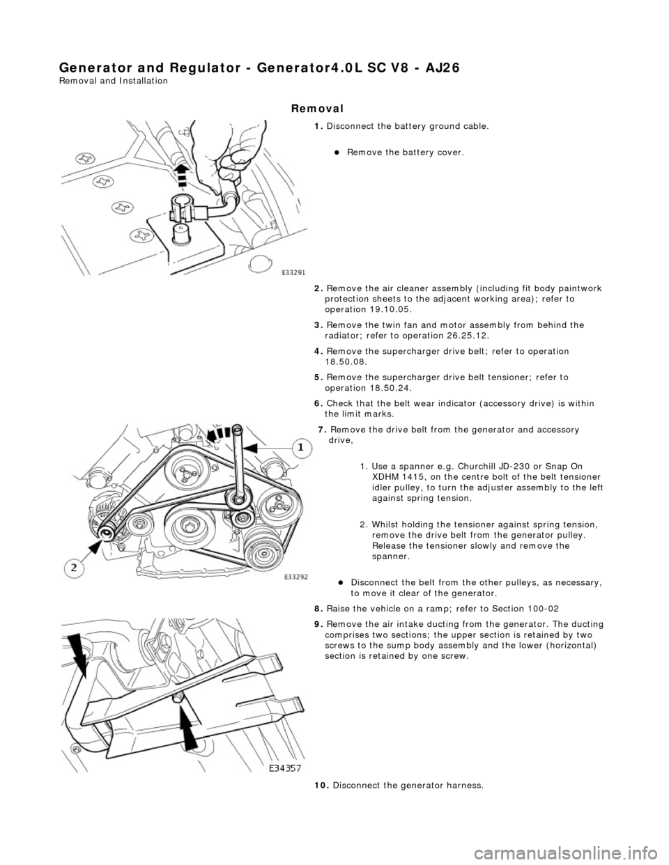
7. Remove the drive belt from the generator and accessory
drive,
1. Use a spanner e.g. Churchill JD-230 or Snap On XDHM 1415, on the centre bo lt of the belt tensioner
idler pulley, to turn the adju ster assembly to the left
against spring tension.
2. Whilst holding the tensioner against spring tension, remove the drive belt from the generator pulley.
Release the tensioner sl owly and remove the
spanner.
Disconnect the belt from the ot her pulleys, as necessary,
to move it clear of the generator.
8. Raise the vehicle on a ramp; refer to Section 100-02
9. Remove the air intake ducting fr om the generator. The ducting
comprises two sections; the upper section is retained by two
screws to the sump body assembly and the lower (horizontal)
section is retained by one screw.
10. Disconnect the generator harness.