1998 JAGUAR X308 climate control
[x] Cancel search: climate controlPage 1766 of 2490
Climate Control System - General Informatio
n - Refrigerant Oil Adding
Gen
e
ral Procedures
CAUTION: Always decant fresh oil from a sealed container and do not leave oil exposed to the atmosphere. PAG oil is
very hygroscopic (absorbs wate r) and will rapidly attract atmospheric moisture. PAG oil must NEVER be mixed with mineral
based oils. Do not re-use oil following a recovery cycle, dispose of it safely.
Original Compressor
New Compressor
1. The amount of oi
l drawn out during a recovery procedure will
be dependent on the state of the system and the rate of
recovery. The quantity will be a pproximately 30 to 40 ml.; this
may vary, and the figure is given only for guidance.
The oil separator vessel in the recovery equipment must be
clean and empty at the start of the process, so that the quantity
of oil which is drawn out may be accurately measured.
• NOTE: The equipment manufactu rer's instructions must be
followed when adding oil directly into an original, or new unit,
owing to rectification work to the existing compressor, or the
need to fit a new compressor.
Oil may be added to the system either via the recovery, recycle
and recharge station or by us ing a proprietary oil injector.
Alternatively, if the compress or has been removed from the
vehicle, the oil may be added directly to the compressor.
1. From an existing compressor, drain the oil into a measuring
cylinder and record the amount. Fl ush the unit out with fresh oil
and drain thoroughly. Replenish the compressor with the same
amount of oil that was originally drained out and immediately
plug all orifices ready for refitting to the vehicle.
1. Drain and discard th e transit lubricating oil from the new
compressor before it is be fitted.
To avoid over-filling the system, an allowance must be made for
the quantity of oil found in the original compressor and the
quantity deposite d in the recovery equipment oil separator from
the charge recovery operation.
Typical example:
D rained
from original compressor - 50 ml.
R
e
covered from oil separator - 40 ml.
Q
u
antity to be put in new compressor - 50 + 40 = 90 ml.
2. The difference between the combined total quantity of
recovered and drained oil and the nominal capacity of the
system (180 ml.), is due to th e quantity of oil remaining in
components such as the cond enser, receiver drier or
evaporator. This oil is no t normally recoverable.
The same procedure may be followed if a problem has occurred
due to oil leakage, as the amount of oil lost is generally small. If
the recovery process has no t been necessary, because
refrigerant has also been lost, then only the quantity drained
from the original compress or needs to be replaced.
Page 1768 of 2490
Climate Control System - General Infor
mation - Refrigerant System Tests
Gen
e
ral Procedures
WARNING: USE EXTREME CARE AND OBSERVE ALL SAFETY PRECAUTIONS RELATED TO THE USE OF REFRIGERANTS.
FAILURE TO FOLLOW THIS INSTRUCTION MAY RESULT IN PERSONAL INJURY.
CAUTION: The A/C refrigerant analyzer mu st be used before the recovery of any vehicle' s A/C refrigerant. Failure to
do so puts workshop bulk refrigerant at risk of contamination. If the vehicle A/C refrigerant is contaminated, refer the
customer to return to the repair facility that carried out the last A/C repair. If the customer wishes to pay the additional
cost, use the A/C recovery equipment that is designated for recovering contaminated A/C refrige rant. All contaminated A/C
refrigerant must be disposed of as hazardous waste. To prevent possible pe rsonal injury, for all equipment, follow the
equipment manufacturer's procedures and instructions.
• NOTE: Jaguar Cars Ltd. supports the effi cient usage, recovery and recycling of the refrigera nt used in passenger car air
conditioners. Jaguar Cars Ltd. recommend s the use of UL-approved recovery/recycling equipment during any A/C system
repair and recharge procedure which requ ires that the system be evacuated.
1. Us
e UL-approved recovery/recycling equipment to evacuate
and recover the A/C system.
Follow t h
e equipment manufacturer's procedures and
instructions for use of equipment.
Page 1798 of 2490
Air Conditioning - Air Conditioning
Description and Operation
Introduction
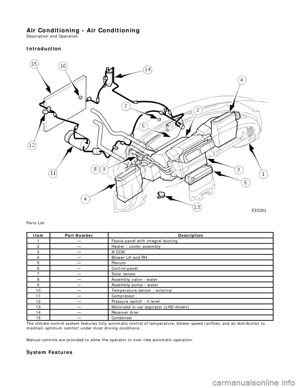
Parts List
The climate control system features fully automatic control of temperature, blower speed (airflow) and air distribution to
maintain optimum comfort under most driving conditions.
Manual controls are provided to allow the operator to over-ride automatic operation.
System Features
ItemPart NumberDescription
1—Fascia panel with integral ducting
2—Heater / cooler assembly
3—A/CCM
4—Blower LH and RH
5—Plenum
6—Control panel
7—Solar sensor
8—Assembly valve - water
9—Assembly pump - water
10—Temperature sensor - external
11—Compressor
12—Pressure switch - 4 level
13—Motorized in-car aspirator (LHD shown)
14—Receiver drier
15—Condenser
Page 1821 of 2490
Control Components - Control Components
Description and Operation
System Controls
The climate control system is controlled by : 1. 1. Manual input from the operator, via the center console located control panel.
2. 2. Automatically by means of the A/CCM.
Output is based upon input from the following devices:
Motorized In-car aspirator External air temperature sensor Coolant temperature sensor Heater 'air-off' (the temperature of the air leaving the matrix fins) temperature sensor Evaporator 'air-off' (the temperature of the air leaving the evaporator fins) temperature sensor Solar sensor Left hand blower recirculation / fresh air flap potentiometer Right hand blower recirculation / fresh air flap potentiometer Upper air distribution box (ADB) center and side face flap servomotor potentiometer ADB defrost flap servomotor potentiometer Air conditioning unit Foot flap servomotor potentiometer Air conditioning unit Cool Air Bypass flap servomotor potentiometer Thumbwheel controls on the facia vent assemblies which provide manu al adjustment of the airflow volume. Road and engine speed signals input to the A/CCM
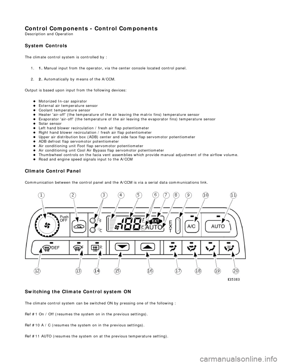
Climate Control Panel
Communication between the control panel and the A/CCM is via a serial data communications link.
Switching the Climate Control system ON
The climate control system can be switched ON by pressing one of the following :
Ref #1 On / Off (resumes the system on in the previous settings).
Ref #10 A / C (resumes the system on in the previous settings).
Ref #11 AUTO (resumes the system on at the previous temperature setting).
Page 1823 of 2490
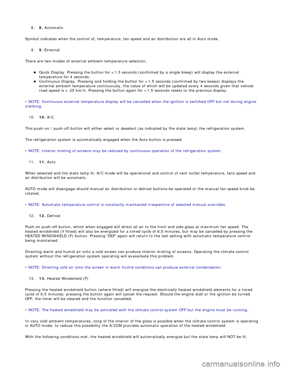
8.8. Automatic
Symbol indicates when the control of , temperature, fan speed and air distribution are all in Auto mode.
9. 9. External
There are two modes of external ambient temperature selection;
Quick Display. Pressing the button for <1.5 seconds (con firmed by a single bleep) will display the external
temperature for 4 seconds.
Continuous Display. Pressing and holding the button fo r >1.5 seconds (confirmed by two beeps) displays the
external ambient temperature continuously, the value of which will be updated every 4 seconds given that vehicle
road speed is > 25 km/h. Pressing the button again fo r <1.5 seconds resets to the previous display.
• NOTE: Continuous external temperature display will be cancel led when the ignition is switched OFF but not during engine
cranking.
10. 10. A/C
This push-on / push-off button will either select or deselect (as indicated by the state lamp) the refrigeration system.
The refrigeration system is automatically engaged when the Auto button is pressed.
• NOTE: Interior misting of screens may be reduced by continuous operation of th e refrigeration system.
11. 11. Auto
When selected and the state lamp lit, A/C mode will be operat ional and control of vent outlet temperature, fans speed and
air distribution will be automatic.
AUTO mode will disengage should manual air distribution or defrost buttons be operated or the manual fan speed knob be
rotated.
• NOTE: Automatic temperature control is constantly main tained irrespective of selected manual overrides.
12. 12. Defrost
Push-on push-off button, which when engaged will direct all air to the front and side glass at maximum fan speed. The
heated windshield (if fitted) will also be energized for a timed cycle of 6,5 minute s, but may be cancelled by pressing the
HEATED WINDSHIELD (F) button. Pressing 'DEF' again will retu rn to the last setting with automatic temperature control
being maintained.
Directing warm and humid air onto a cold screen can produce interior misting of screens. Operating the climate control
system without the refrigerati on system operating will exacerbate this problem.
• NOTE: Directing cold air onto the screen in warm humid conditions can produce external condensation.
13. 13. Heated Windshield (F)
Pressing the heated windshield button (whe re fitted) will energize the electrically heated windshield elements for a timed
cycle of 6,5 minutes; pressing the button again will cancel the request. Should the engine stall or the ignition be turned
OFF, the timer will be cleare d and the function cancelled.
• NOTE: The heated windshield may be activated with the cl imate control system OFF but the engine must be running.
In very cold ambient temperatures, icing of the interior of the glass is possible when the climate control system is operating
in AUTO mode; to reduce this poss ibility the A/CCM provides automatic operation of the heated windshield.
With the following conditions met, the heated windshield will automatically energize but the state lamp will NOT be lit.
Page 1824 of 2490
External temperature < -10 °C Vehicle speed > 65 km / h The first two conditions exist > 2 minutes. Engine speed > 50 revs / min
14. 14. Heated Backlight (R)
Pressing the heated backlight button will simultaneously energize the heater elements for timed cycles of;
21 minutes backlight 11 minutes exterior mirrors
Pressing the button again within the 21 minute timer will cancel the request.
If the engine is stalled, or the ignition switched OFF, the backlight and door mirror timers will be cleared, resulting in both
functions being switched off.
• NOTE: Both the backlight and door mirrors may be activated with the climate control system OFF, but the engine must be
running.
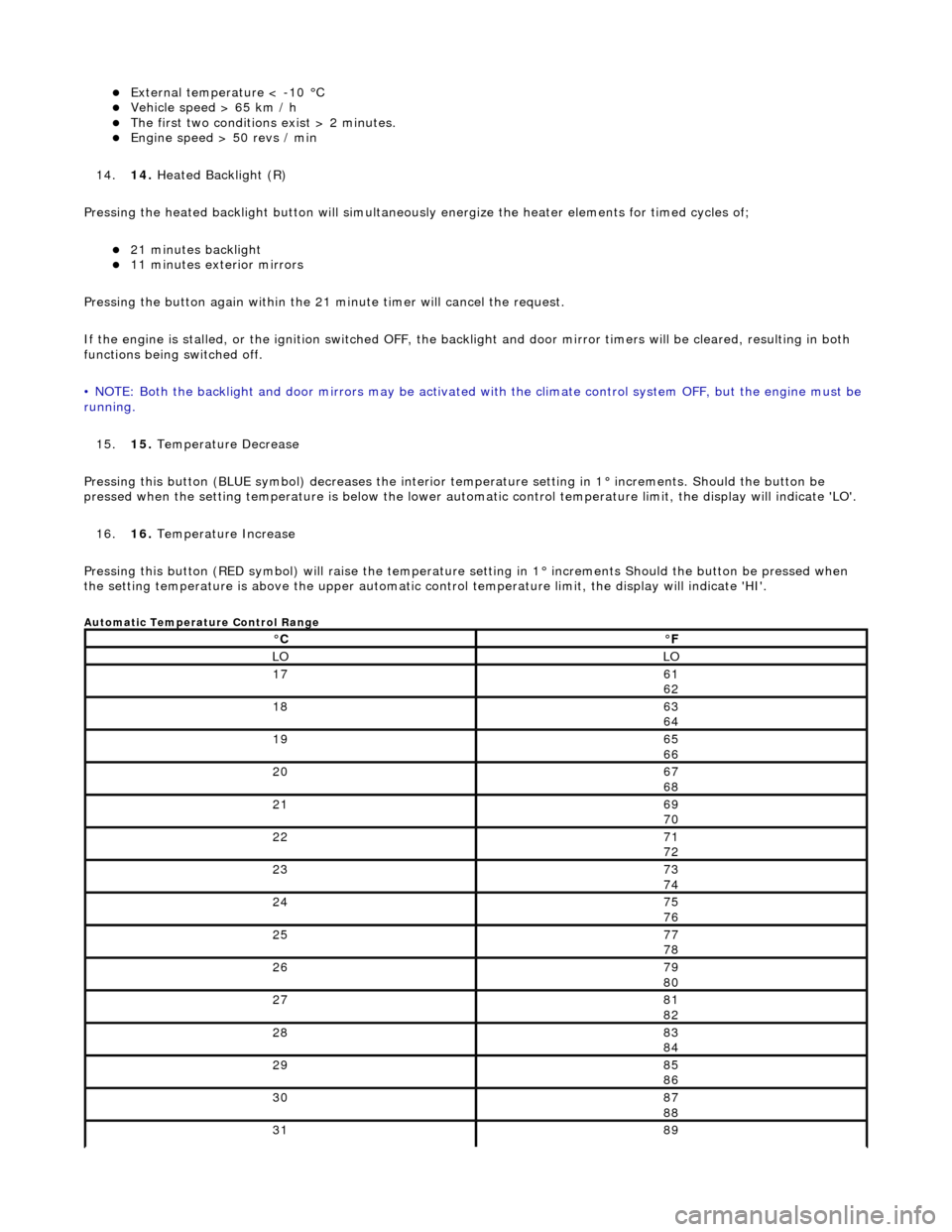
15. 15. Temperature Decrease
Pressing this button (BLUE symbol) decreases the interior temperature setting in 1° increments. Should the button be
pressed when the setting temperature is below the lower automatic control temperature limit, the display will indicate 'LO'.
16. 16. Temperature Increase
Pressing this button (RED symbol) will raise the temperature setting in 1° increments Should the button be pressed when
the setting temperature is above the upper automatic control temperature limit, the display will indicate 'HI'.
Automatic Temperature Control Range
°C°F
LOLO
1761
62
1863
64
1965
66
2067
68
2169
70
2271
72
2373
74
2475
76
2577
78
2679
80
2781
82
2883
84
2985
86
3087
88
3189
Page 1835 of 2490
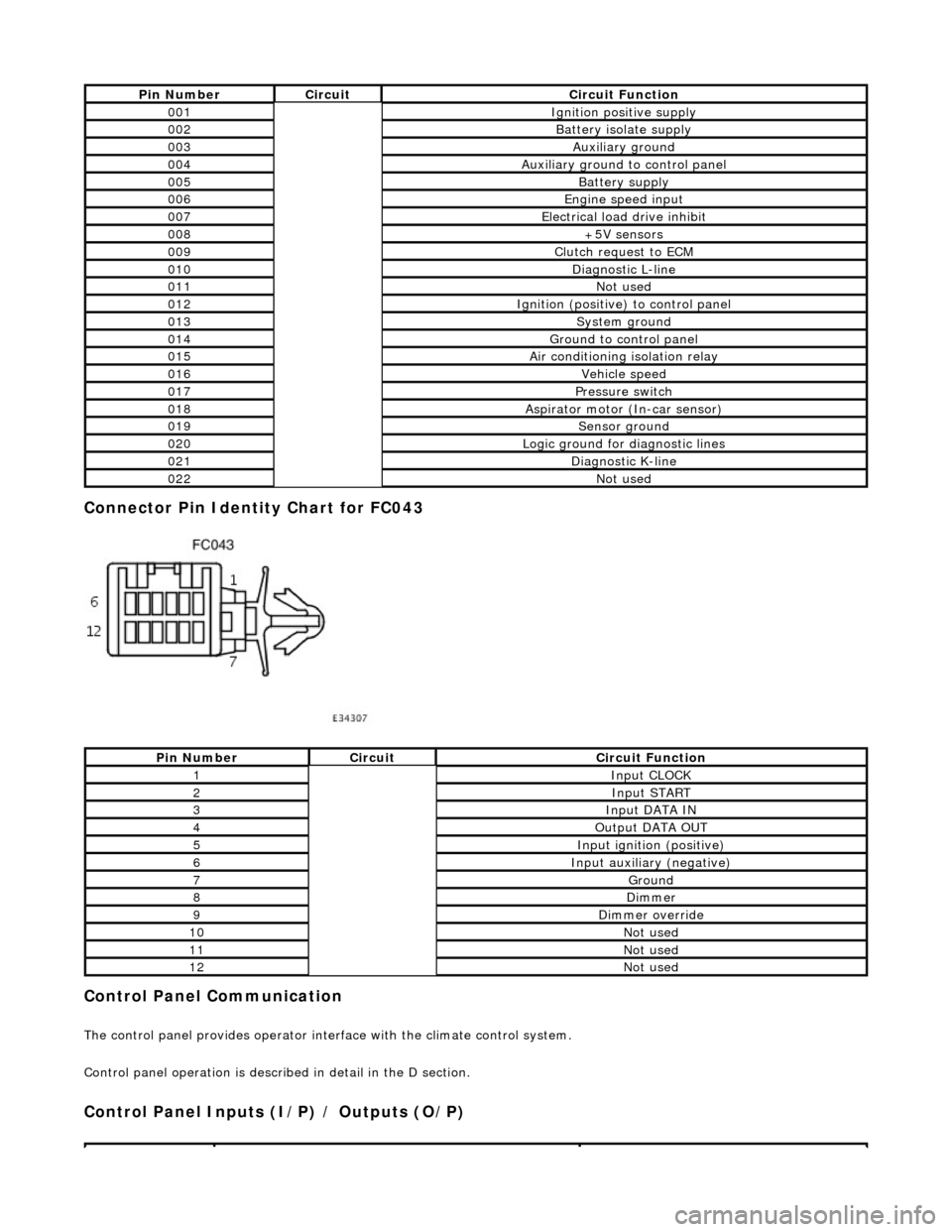
Connector Pin Identity Chart for FC043
Control Panel Communication
The control panel provides operator interface with the climate control system.
Control panel operation is described in detail in the D section.
Control Panel Inputs (I/P) / Outputs (O/P)
Pin NumberCircuitCircuit Function
001Ignition positive supply
002Battery isolate supply
003Auxiliary ground
004Auxiliary ground to control panel
005Battery supply
006Engine speed input
007Electrical load drive inhibit
008+5V sensors
009Clutch request to ECM
010Diagnostic L-line
011Not used
012Ignition (positive) to control panel
013System ground
014Ground to control panel
015Air conditioning isolation relay
016Vehicle speed
017Pressure switch
018Aspirator motor (In-car sensor)
019Sensor ground
020Logic ground for diagnostic lines
021Diagnostic K-line
022Not used
Pin NumberCircuitCircuit Function
1Input CLOCK
2Input START
3Input DATA IN
4Output DATA OUT
5Input ignition (positive)
6Input auxiliary (negative)
7Ground
8Dimmer
9Dimmer override
10Not used
11Not used
12Not used
Page 1836 of 2490
System Self-test
Control Panel Interrogation Procedure
The control panel has a self-diagnosis feature, and is capable of displaying and clearing stored fault codes.
Climate control is an integrated system, therefore it is recommended that the PDU is used for fault diagnosis. The fault
codes displayed with the control panel self -diagnosis feature are not as comprehensive as those of the PDU. The PDU will
display the relevant fault code, fault co de description and information of the system peripherals at the time the fault
occurred.
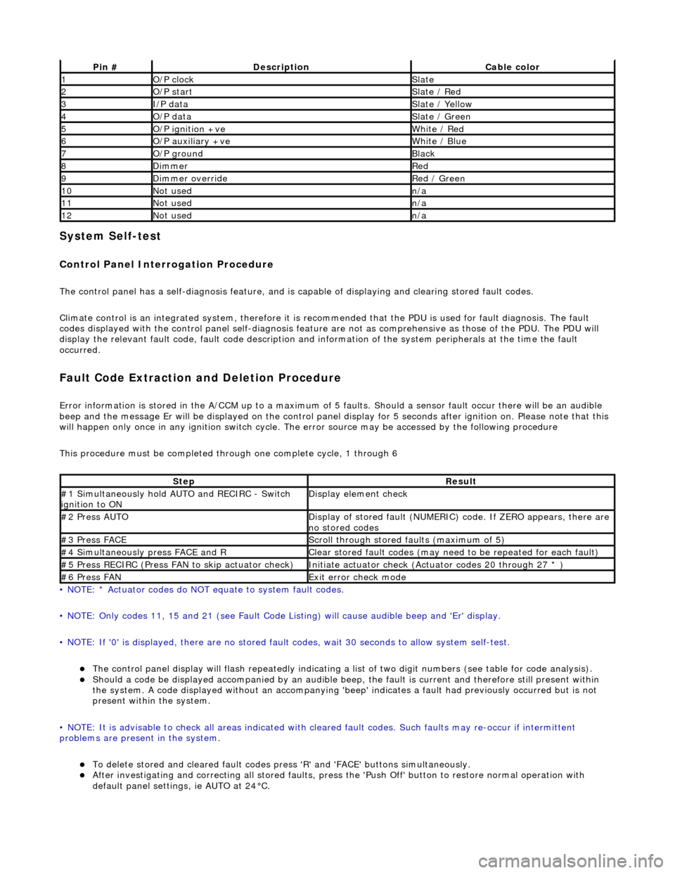
Fault Code Extraction and Deletion Procedure
Error information is stored in the A/CCM up to a maximum of 5 faults. Should a sensor fault occur there will be an audible
beep and the message Er will be displayed on the control panel display for 5 seco nds after ignition on. Please note that this
will happen only once in any ignition switch cycle. The error source may be accessed by the following procedure
This procedure must be completed through one complete cycle, 1 through 6
• NOTE: * Actuator codes do NOT equate to system fault codes.
• NOTE: Only codes 11, 15 and 21 (see Fault Code List ing) will cause audible beep and 'Er' display.
• NOTE: If '0' is displayed, there are no stored faul t codes, wait 30 seconds to allow system self-test.
The control panel display will flash repeatedly indicating a list of two digit numbers (see table for code analysis). Should a code be displayed accompanied by an audible beep, the fault is current and therefore still present within
the system. A code displayed without an accompanying 'bee p' indicates a fault had previously occurred but is not
present within the system.
• NOTE: It is advisable to check all areas indicated with cleared fault codes. Such faults may re-occur if intermittent
problems are present in the system.
To delete stored and cleared fault codes press 'R' and 'FAC E' buttons simultaneously. After investigating and correcting all stored faults, press the 'Push Off' button to restore normal operation with
default panel settings, ie AUTO at 24°C.
Pin #DescriptionCable color
1O/P clockSlate
2O/P startSlate / Red
3I/P dataSlate / Yellow
4O/P dataSlate / Green
5O/P ignition +veWhite / Red
6O/P auxiliary +veWhite / Blue
7O/P groundBlack
8DimmerRed
9Dimmer overrideRed / Green
10Not usedn/a
11Not usedn/a
12Not usedn/a
StepResult
#1 Simultaneously hold AU TO and RECIRC - Switch
ignition to ONDisplay element check
#2 Press AUTODisplay of stored fault (NUMERIC) code. If ZERO appears, there are
no stored codes
#3 Press FACEScroll through stored faults (maximum of 5)
#4 Simultaneously press FACE and RClear stored fault codes (may need to be repeated for each fault)
#5 Press RECIRC (Press FAN to skip actuator check)Initiate actuator check (Actuator codes 20 through 27 * )
#6 Press FANExit error check mode