1998 JAGUAR X308 ECO mode
[x] Cancel search: ECO modePage 1464 of 2490
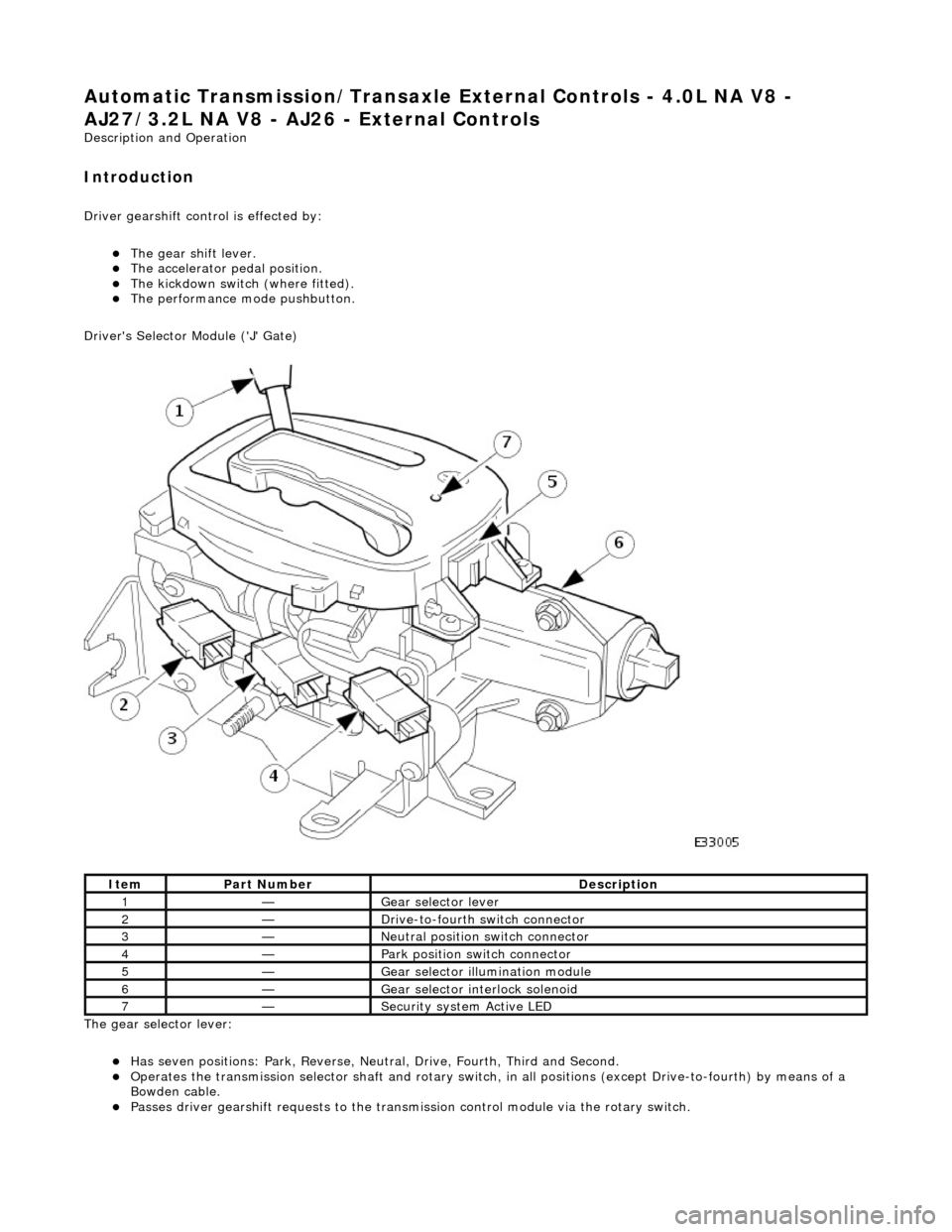
Automatic Transmission/Transaxle External Controls - 4.0L NA V8 -
AJ27/3.2L NA V8 - AJ26 - External Controls
Description and Operation
Introduction
Driver gearshift control is effected by:
The gear shift lever. The accelerator pedal position. The kickdown switch (where fitted). The performance mode pushbutton.
Driver's Selector Module ('J' Gate)
The gear selector lever:
Has seven positions: Park, Reverse, Neutral, Drive, Fourth, Third and Second. Operates the transmission selector shaft and rotary switch, in all positions (except Drive-to-fourth) by means of a
Bowden cable.
Passes driver gearshift requests to the transm ission control module via the rotary switch.
ItemPart NumberDescription
1—Gear selector lever
2—Drive-to-fourth switch connector
3—Neutral position switch connector
4—Park position switch connector
5—Gear selector illumination module
6—Gear selector interlock solenoid
7—Security system Active LED
Page 1743 of 2490
Accelerati
on Control - Accelerator Cable Adjustment
Gen
eral Procedures
1.
Load the Approved Jaguar Diagno stic System with power train
data logger.
2. Connect the Approved Jaguar Diag nostic System to the vehicle.
3. W
ith 'Disable Network Integrity Test - YES/ NO' displayed on
the screen select YES.
4. With new menu displayed on the screen, select ' Engine
Management'.
5. Turn the ignition to ON.
R
emove any previously selected data logger parameters.
6. On data logger select PPS11 an d PPS2 (Pedal demand sensors
1 and 2).
7. On Sedan models only, remove the bulkhead covers on both
sides and the engine compartment rear cover.
8. Cut, remove and discard the ra tchet strap which retains the
throttle cable to the abutment bracket.
9. Ensure there is no tension on the throttle cable by releasing
the throttle cable adjustment nut from the abutment bracket.
10. Record the voltages for both sensors, PPS11 and PPS2.
11. Partially insert the throttle cable adjustment nut into the
abutment bracket.
12. Recheck the voltages for both sensors, PPS11 and PPS2.
13. Where the voltages at step 12 are higher than the voltages
taken at step 10, contin ue to step 15 below.
14. Where the voltages at step 12 are the same as the voltages
taken at step 10, contin ue to step 16 below.
15. Rotate the adjustment nut clockwise (as viewed from the
front of the vehicle) until the same voltages are indicated as in
step 10. Continue to turn thro ugh a part revolution until the
sides of the nut are vertical. Tu rn through a further 90 degrees,
then fully insert the nut into the abutment bracket.
16. Rotate the adjustment nut anti-clockwise (as viewed from the
front of the vehicle) until the indicated voltage starts to
increase. Then rotate the nut clockwise through a part
revolution until the sides are ve rtical. Turn through a further 90
degrees, then fully insert the nut into the abutment bracket.
17. Fit a new ratchet strap to secure the throttle cable adjusting
nut to the abutment bracket.
18. Operate the throttle pedal through 20 full cycles to settle the
cable. Check the voltages now shown, remain the same as in
steps 15 and 16.
19. Check and where necessary adjust the kickdown switch. For
additional information, refer to Section 307
-05A Automatic Transmissi
on/Transaxle External Controls
Sectio
n
307
-05
B
Au
tomatic Transmission/Tra
nsaxle External Controls
.
20
.
On Sedan models only, refit the engine compartment rear
cover and the bulkhead co vers on both sides.
21. Switch the ignition OFF and disconnect the Approved Jaguar
Diagnostic System.
Page 1756 of 2490
Probable
causes of faults may be found by comparing actual
system pressures, registered on your manifold gauge set or
recovery / recharge / recycle station, and the relevant pressure to temperature relationship graph. The following chart
shows the interpretation that ma y be made by this difference.
• NOTE: The A/CCM will disengage the compressor clutch should the evaporator temperature fall to 0°C.
• NOTE: Graphs are typical for HFC 134A
The 'Normal' condition is that which is relevant to the prevailing evaporator temperature.
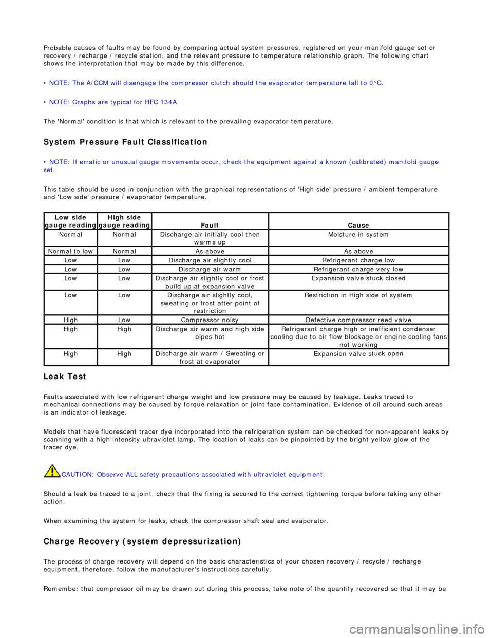
System Pressure Fault Classification
• NOTE
: If erratic or unusual gauge move
ments occur, check the equipment against a known (calibrated) manifold gauge
set.
This table should be used in conjunction with the graphical representations of 'High side' pressure / ambient temperature
and 'Low side' pressure / evaporator temperature.
Leak
Test
F
a
ults associated with low re
frigerant charge weight and low pressure ma y be caused by leakage. Leaks traced to
mechanical connections may be caused by to rque relaxation or joint face contamination. Evidence of oil around such areas
is an indicator of leakage.
Models that have fluorescent tracer dye incorporated into the refrigeration system can be checke d for non-apparent leaks by
scanning with a high intensity ultraviolet lamp. The location of leaks can be pinpointed by the bright yellow glow of the
tracer dye.
CAUTION: Observe ALL safety precautions associated with ultraviolet equipment.
Should a leak be traced to a joint, check that the fixing is secured to the correct tightening torque before taking any other
action.
When examining the system for leaks, chec k the compressor shaft seal and evaporator.
Charge Re
covery (system depressurization)
The process of
charge r
ecovery will depe
nd on the basic characteristics of your chosen recovery / recycle / recharge
equipment, therefore, follow the manu facturer's instructions carefully.
Remember that compressor oil may be drawn out during this process, take note of the quantity recovered so that it may be
Lo
w side
gauge reading
High s i
de
gauge reading
Fau l
t
Cause
No
r
mal
No
r
mal
Di
sc
harge air initially cool then
warms up
Mois
ture in system
N
ormal
to low
No
r
mal
As aboveAs above
LowLowD
i
scharge air slightly cool
Ref
r
igerant charge low
LowLowDi
scharge air warm
Refr
igerant charge very low
LowLowDi
scharge air slightly cool or frost
build up at expansion valve
Expansion valve st
uck closed
LowLowDi
scharge air slightly cool,
sweating or frost after point of restriction
Restri
ction in High side of system
HighLowCompressor noisyDe
fe
ctive compressor reed valve
HighHighD
i
scharge air warm and high side
pipes hot
Refri
gerant charge high or inefficient condenser
cooling due to air flow blockage or engine cooling fans
not working
HighHighD i
scharge air warm / Sweating or
frost at evaporator
Expans ion valve st
uck open
Page 1758 of 2490
Climate Control System - General Informatio
n - Climate Control System
D
iagn
osis and Testing
I
n
troduction
It is very i
m
portant to positive
ly identify the area of concern before starting a rectification procedure. A little time spent with
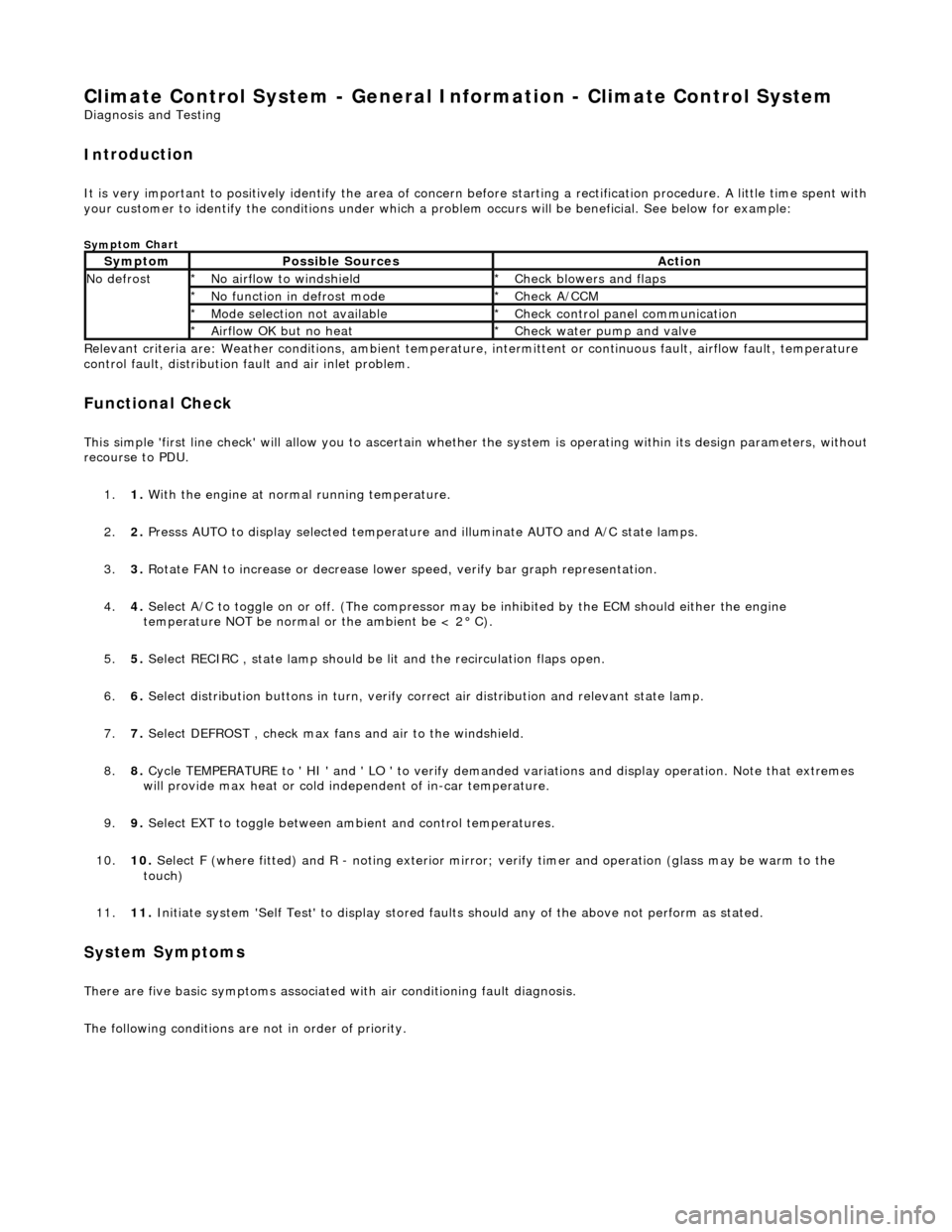
your customer to identify the conditions under which a pr oblem occurs will be beneficial. See below for example:
Sym
ptom Chart
Re
lev
ant criteria are: Weather conditions,
ambient temperature, intermittent or cont inuous fault, airflow fault, temperature
control fault, distribution fault and air inlet problem.
Functio n
al Check
This
s
imple 'first line check' will allo
w you to ascertain whether the system is operating within its design parameters, withou t
recourse to PDU.
1. 1. With the engine at normal running temperature.
2. 2. Presss AUTO to display selected temperature and illuminate AUTO and A/C state lamps.
3. 3. Rotate FAN to increase or decrease lowe r speed, verify bar graph representation.
4. 4. Select A/C to toggle on or off. (T he compressor may be inhibited by the ECM should either the engine
temperature NOT be normal or the ambient be < 2° C).
5. 5. Select RECIRC , state lamp should be lit and the recirculation flaps open.
6. 6. Select distribution butt ons in turn, verify correct air distribution and relevant state lamp.
7. 7. Select DEFROST , check max fans and air to the windshield.
8. 8. Cycle TEMPERATURE to ' HI ' and ' LO ' to verify demanded variations and display operation. Note that extremes
will provide max heat or cold independent of in-car temperature.
9. 9. Select EXT to toggle between am bient and control temperatures.
10. 10. Select F (where fitted) and R - noting exterior mirror; verify timer and operation (glass may be warm to the
touch)
11. 11. Initiate system 'Self Test' to display stored faul ts should any of the above not perform as stated.
Sy
stem Symptoms
There
are five
basic symptoms associated
with air conditioning fault diagnosis.
The following conditions are not in order of priority.
Sy m
ptom
Possib
l
e Sources
Acti
o
n
N
o defrostN o
airflow to windshield
*
Check blower s and flaps
*
N o functi
on in defrost mode
*
Check A/CCM
*
Mo de s
election not available
*
Chec k
control panel communication
*
Ai rfl
ow OK but no heat
*
Check water pu
mp and valve
*
Page 1822 of 2490
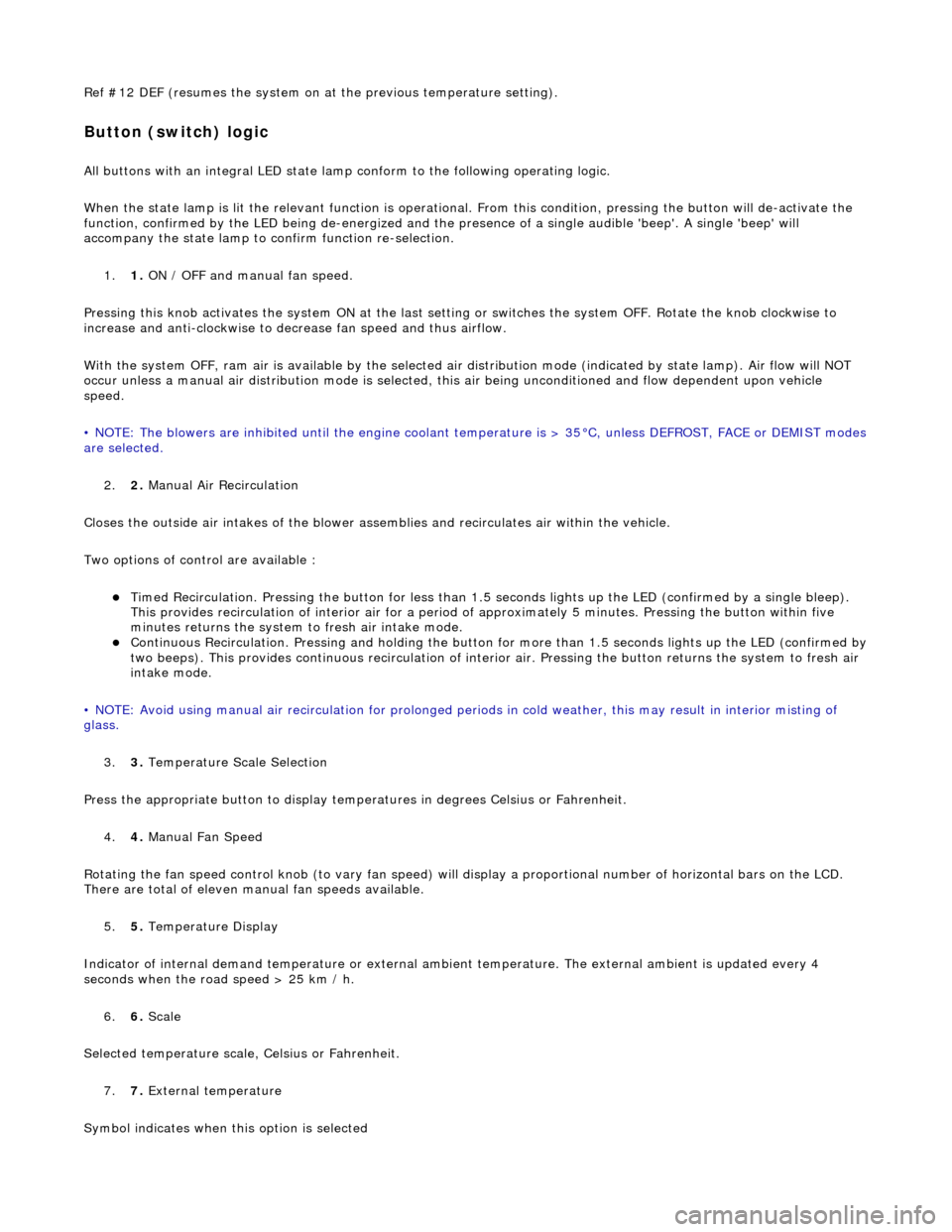
Ref #12 DEF (resumes the system on at the previous temperature setting).
Button (switch) logic
All buttons with an integral LED state lamp conform to the following operating logic.
When the state lamp is lit the relevant func tion is operational. From this condition, pressing the button will de-activate the
function, confirmed by the LED being de-energized and the pres ence of a single audible 'beep'. A single 'beep' will
accompany the state lamp to confirm function re-selection.
1. 1. ON / OFF and manual fan speed.
Pressing this knob activates the system ON at the last settin g or switches the system OFF. Rotate the knob clockwise to
increase and anti-clockwise to decrease fan speed and thus airflow.
With the system OFF, ram air is available by the selected air di stribution mode (indicated by state lamp). Air flow will NOT
occur unless a manual air distribution mo de is selected, this air being unconditioned and flow dependent upon vehicle
speed.
• NOTE: The blowers are inhibited until the engine coolant te mperature is > 35°C, unless DEFROST, FACE or DEMIST modes
are selected.
2. 2. Manual Air Recirculation
Closes the outside air intakes of the blower asse mblies and recirculates air within the vehicle.
Two options of control are available :
Timed Recirculation. Pressing the button for less than 1.5 seconds lights up the LED (confirmed by a single bleep).
This provides recirculation of interior air for a period of approximately 5 minutes. Pressing the button within five
minutes returns the system to fresh air intake mode.
Continuous Recirculation. Pressing and holding the button for more than 1.5 seconds lights up the LED (confirmed by two beeps). This provides continuous reci rculation of interior air. Pressing the button returns the system to fresh air
intake mode.
• NOTE: Avoid using manual air recirculatio n for prolonged periods in cold weather, this may result in interior misting of
glass.
3. 3. Temperature Scale Selection
Press the appropriate button to display temperatures in degrees Celsius or Fahrenheit.
4. 4. Manual Fan Speed
Rotating the fan speed control knob (to vary fan speed) will di splay a proportional number of horizontal bars on the LCD.
There are total of eleven manual fan speeds available.
5. 5. Temperature Display
Indicator of internal demand temperatur e or external ambient temperature. The external ambient is updated every 4
seconds when the road speed > 25 km / h.
6. 6. Scale
Selected temperature scale, Celsius or Fahrenheit.
7. 7. External temperature
Symbol indicates when this option is selected
Page 1823 of 2490
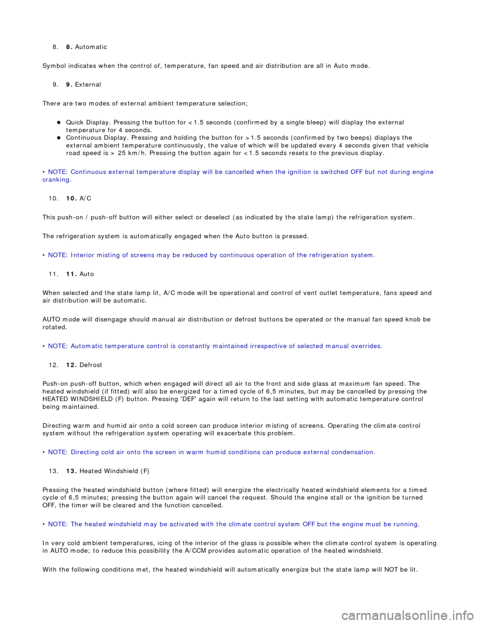
8.8. Automatic
Symbol indicates when the control of , temperature, fan speed and air distribution are all in Auto mode.
9. 9. External
There are two modes of external ambient temperature selection;
Quick Display. Pressing the button for <1.5 seconds (con firmed by a single bleep) will display the external
temperature for 4 seconds.
Continuous Display. Pressing and holding the button fo r >1.5 seconds (confirmed by two beeps) displays the
external ambient temperature continuously, the value of which will be updated every 4 seconds given that vehicle
road speed is > 25 km/h. Pressing the button again fo r <1.5 seconds resets to the previous display.
• NOTE: Continuous external temperature display will be cancel led when the ignition is switched OFF but not during engine
cranking.
10. 10. A/C
This push-on / push-off button will either select or deselect (as indicated by the state lamp) the refrigeration system.
The refrigeration system is automatically engaged when the Auto button is pressed.
• NOTE: Interior misting of screens may be reduced by continuous operation of th e refrigeration system.
11. 11. Auto
When selected and the state lamp lit, A/C mode will be operat ional and control of vent outlet temperature, fans speed and
air distribution will be automatic.
AUTO mode will disengage should manual air distribution or defrost buttons be operated or the manual fan speed knob be
rotated.
• NOTE: Automatic temperature control is constantly main tained irrespective of selected manual overrides.
12. 12. Defrost
Push-on push-off button, which when engaged will direct all air to the front and side glass at maximum fan speed. The
heated windshield (if fitted) will also be energized for a timed cycle of 6,5 minute s, but may be cancelled by pressing the
HEATED WINDSHIELD (F) button. Pressing 'DEF' again will retu rn to the last setting with automatic temperature control
being maintained.
Directing warm and humid air onto a cold screen can produce interior misting of screens. Operating the climate control
system without the refrigerati on system operating will exacerbate this problem.
• NOTE: Directing cold air onto the screen in warm humid conditions can produce external condensation.
13. 13. Heated Windshield (F)
Pressing the heated windshield button (whe re fitted) will energize the electrically heated windshield elements for a timed
cycle of 6,5 minutes; pressing the button again will cancel the request. Should the engine stall or the ignition be turned
OFF, the timer will be cleare d and the function cancelled.
• NOTE: The heated windshield may be activated with the cl imate control system OFF but the engine must be running.
In very cold ambient temperatures, icing of the interior of the glass is possible when the climate control system is operating
in AUTO mode; to reduce this poss ibility the A/CCM provides automatic operation of the heated windshield.
With the following conditions met, the heated windshield will automatically energize but the state lamp will NOT be lit.
Page 1825 of 2490
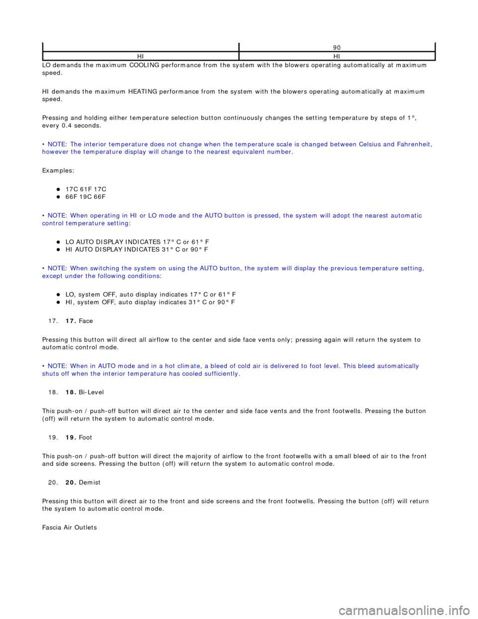
LO demands the maximum COOLING performance from the system with the blowers operating automatically at maximum
speed.
HI demands the maximum HEATING performance from the system with the blowers operating automatically at maximum
speed.
Pressing and holding either temperature selection button co ntinuously changes the setting temperature by steps of 1°,
every 0.4 seconds.
• NOTE: The interior temperature does not change when the temperature scale is changed between Celsius and Fahrenheit,
however the temperature display will chan ge to the nearest equivalent number.
Examples:
17C 61F 17C 66F 19C 66F
• NOTE: When operating in HI or LO mode and the AUTO butt on is pressed, the system will adopt the nearest automatic
control temperature setting:
LO AUTO DISPLAY INDICATES 17° C or 61° F HI AUTO DISPLAY INDICATES 31° C or 90° F
• NOTE: When switching the system on us ing the AUTO button, the system will display the previous temperature setting,
except under the following conditions:
LO, system OFF, auto display indicates 17° C or 61° F HI, system OFF, auto display indicates 31° C or 90° F
17. 17. Face
Pressing this button will direct all airflow to the center and side face vents only; pressing again will return the system to
automatic control mode.
• NOTE: When in AUTO mode and in a hot c limate, a bleed of cold air is delivered to foot level. This bleed automatically
shuts off when the inte rior temperature has cooled sufficiently.
18. 18. Bi-Level
This push-on / push-off button will direct air to the center and side face vent s and the front footwells. Pressing the button
(off) will return the system to automatic control mode.
19. 19. Foot
This push-on / push-off button will direct the majority of airflow to the front footwells with a small bleed of air to the fron t
and side screens. Pressing the button (off) will return the system to automatic control mode.
20. 20. Demist
Pressing this button will direct air to the front and side screens and the front foot wells. Pressing the button (off) will return
the system to automatic control mode.
Fascia Air Outlets
90
HIHI
Page 1836 of 2490
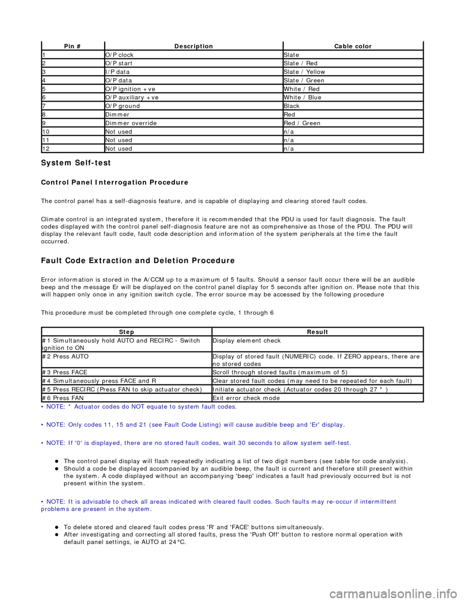
System Self-test
Control Panel Interrogation Procedure
The control panel has a self-diagnosis feature, and is capable of displaying and clearing stored fault codes.
Climate control is an integrated system, therefore it is recommended that the PDU is used for fault diagnosis. The fault
codes displayed with the control panel self -diagnosis feature are not as comprehensive as those of the PDU. The PDU will
display the relevant fault code, fault co de description and information of the system peripherals at the time the fault
occurred.
Fault Code Extraction and Deletion Procedure
Error information is stored in the A/CCM up to a maximum of 5 faults. Should a sensor fault occur there will be an audible
beep and the message Er will be displayed on the control panel display for 5 seco nds after ignition on. Please note that this
will happen only once in any ignition switch cycle. The error source may be accessed by the following procedure
This procedure must be completed through one complete cycle, 1 through 6
• NOTE: * Actuator codes do NOT equate to system fault codes.
• NOTE: Only codes 11, 15 and 21 (see Fault Code List ing) will cause audible beep and 'Er' display.
• NOTE: If '0' is displayed, there are no stored faul t codes, wait 30 seconds to allow system self-test.
The control panel display will flash repeatedly indicating a list of two digit numbers (see table for code analysis). Should a code be displayed accompanied by an audible beep, the fault is current and therefore still present within
the system. A code displayed without an accompanying 'bee p' indicates a fault had previously occurred but is not
present within the system.
• NOTE: It is advisable to check all areas indicated with cleared fault codes. Such faults may re-occur if intermittent
problems are present in the system.
To delete stored and cleared fault codes press 'R' and 'FAC E' buttons simultaneously. After investigating and correcting all stored faults, press the 'Push Off' button to restore normal operation with
default panel settings, ie AUTO at 24°C.
Pin #DescriptionCable color
1O/P clockSlate
2O/P startSlate / Red
3I/P dataSlate / Yellow
4O/P dataSlate / Green
5O/P ignition +veWhite / Red
6O/P auxiliary +veWhite / Blue
7O/P groundBlack
8DimmerRed
9Dimmer overrideRed / Green
10Not usedn/a
11Not usedn/a
12Not usedn/a
StepResult
#1 Simultaneously hold AU TO and RECIRC - Switch
ignition to ONDisplay element check
#2 Press AUTODisplay of stored fault (NUMERIC) code. If ZERO appears, there are
no stored codes
#3 Press FACEScroll through stored faults (maximum of 5)
#4 Simultaneously press FACE and RClear stored fault codes (may need to be repeated for each fault)
#5 Press RECIRC (Press FAN to skip actuator check)Initiate actuator check (Actuator codes 20 through 27 * )
#6 Press FANExit error check mode