Page 802 of 2490

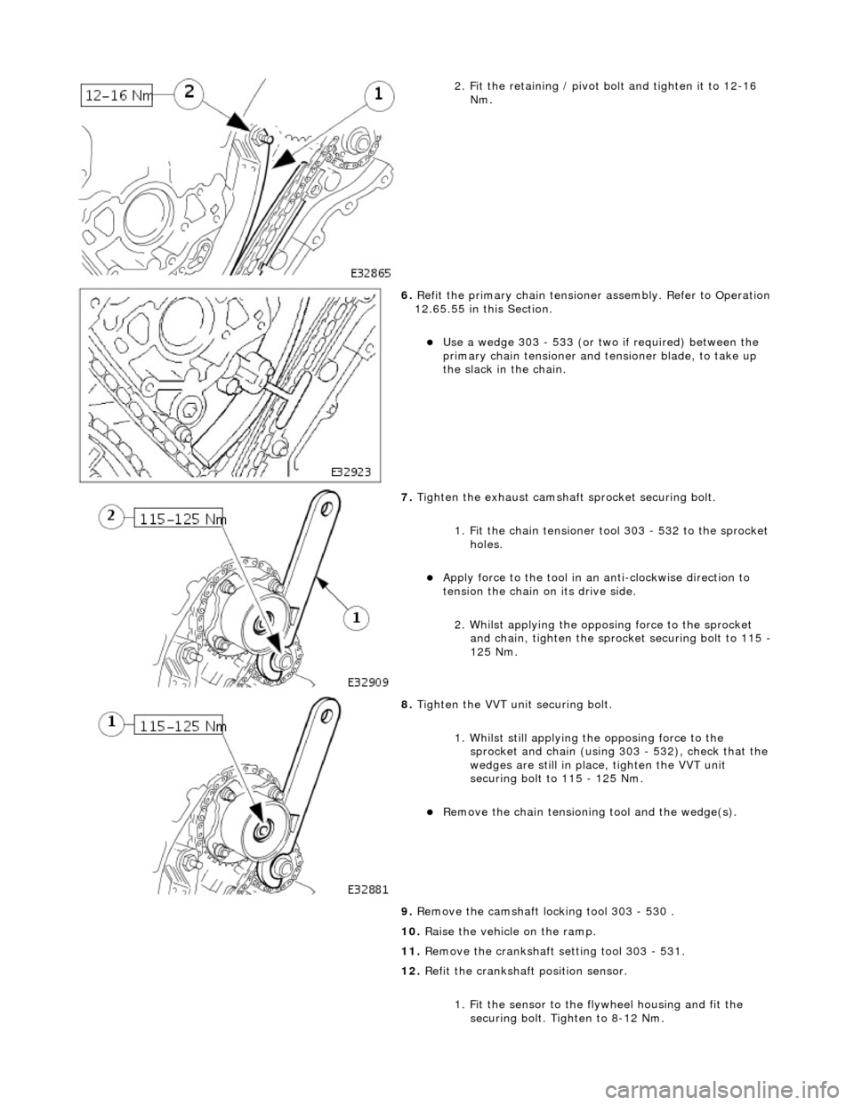
2. Fit the retaining / pivot bolt and tighten it to 12-16 Nm.
6. Refit the primary chain tensione r assembly. Refer to Operation
12.65.55 in this Section.
Use a wedge 303 - 533 (or two if required) between the
primary chain tensioner and te nsioner blade, to take up
the slack in the chain.
7. Tighten the exhaust camshaft sprocket securing bolt.
1. Fit the chain tensioner tool 303 - 532 to the sprocket holes.
Apply force to the tool in an anti-clockwise direction to
tension the chain on its drive side.
2. Whilst applying the opposing force to the sprocket and chain, tighten the sprock et securing bolt to 115 -
125 Nm.
8. Tighten the VVT unit securing bolt.
1. Whilst still applying the opposing force to the
sprocket and chain (using 303 - 532), check that the
wedges are still in place, tighten the VVT unit
securing bolt to 115 - 125 Nm.
Remove the chain tensioning tool and the wedge(s).
9. Remove the camshaft locking tool 303 - 530.
10. Raise the vehicle on the ramp.
11. Remove the crankshaft setting tool 303 - 531.
12. Refit the crankshaft position sensor.
1. Fit the sensor to the fl ywheel housing and fit the
securing bolt. Tighten to 8-12 Nm.
Page 808 of 2490

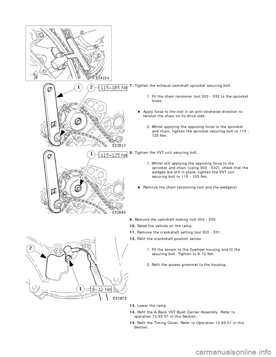
7. Tighten the exhaust camshaft sprocket securing bolt.
1. Fit the chain tensioner tool 303 - 532 to the sprocket holes.
Apply force to the tool in an anti-clockwise direction to
tension the chain on its drive side.
2. Whilst applying the opposing force to the sprocket and chain, tighten the sprock et securing bolt to 115 -
125 Nm.
8. Tighten the VVT unit securing bolt.
1. Whilst still applying the opposing force to the
sprocket and chain (using 303 - 532), check that the
wedges are still in place, tighten the VVT unit
securing bolt to 115 - 125 Nm.
Remove the chain tensioning tool and the wedge(s).
9. Remove the camshaft locking tool 303 - 530.
10. Raise the vehicle on the ramp.
11. Remove the crankshaft setting tool 303 - 531.
12. Refit the crankshaft position sensor.
1. Fit the sensor to the fl ywheel housing and fit the
securing bolt. Tighten to 8-12 Nm.
2. Refit the access grommet to the housing.
13. Lower the ramp.
14. Refit the A-Bank VVT Bush Carrier Assembly. Refer to
operation 12.65.51 in this Section.
15. Refit the Timing Cover. Refer to Operation 12.65.01 in this
Section.
Page 813 of 2490

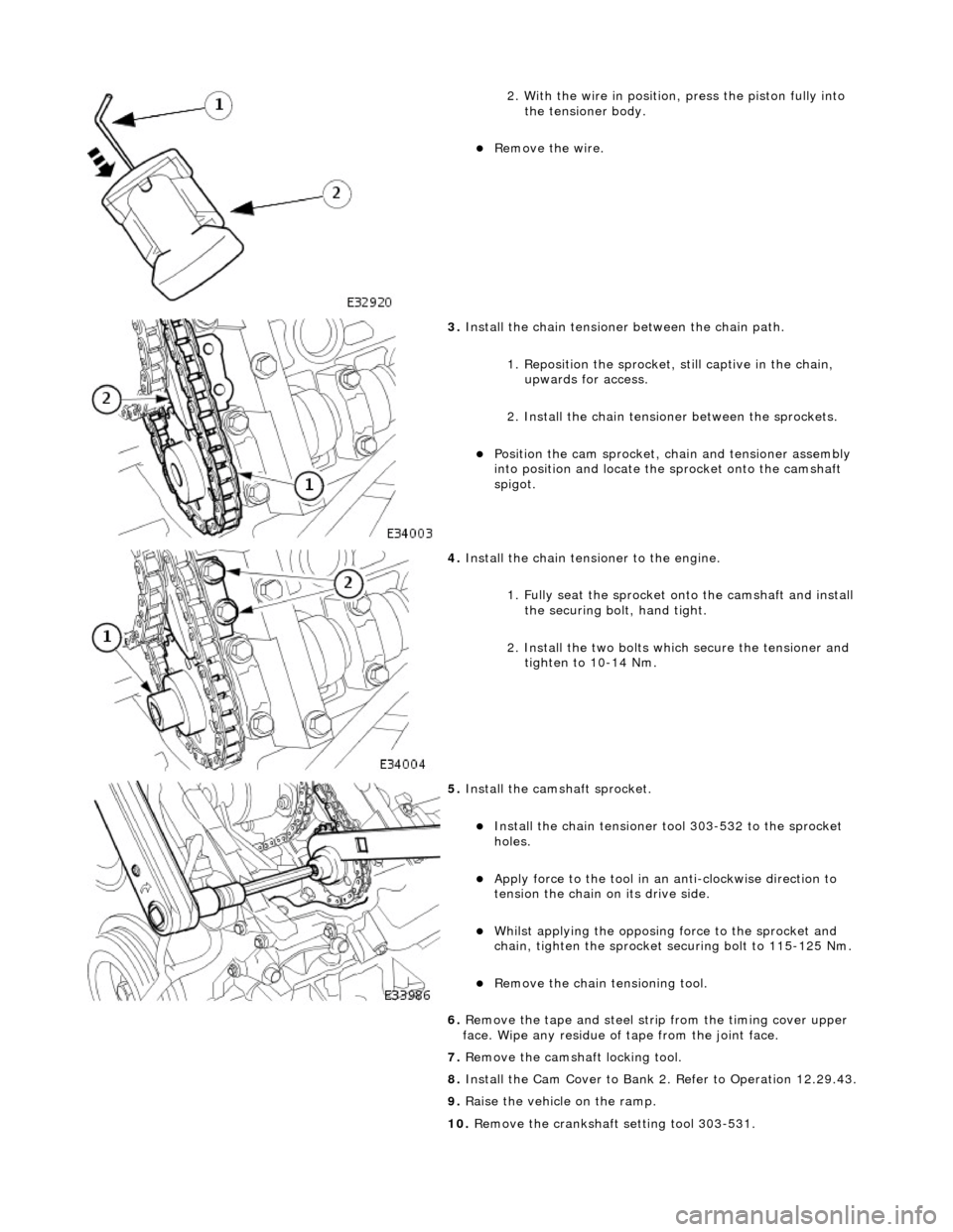
2. With the wire in position, press the piston fully into the tensioner body.
Remove the wire.
3. Install the chain tensioner between the chain path.
1. Reposition the sprocket, still captive in the chain, upwards for access.
2. Install the chain tensioner between the sprockets.
Position the cam sprocket, chain and tensioner assembly
into position and locate the sprocket onto the camshaft
spigot.
4. Install the chain tensioner to the engine.
1. Fully seat the sprocket onto the camshaft and install the securing bolt, hand tight.
2. Install the two bolts which secure the tensioner and tighten to 10-14 Nm.
5. Install the cams haft sprocket.
Install the chain tensioner tool 303-532 to the sprocket
holes.
Apply force to the tool in an anti-clockwise direction to
tension the chain on its drive side.
Whilst applying the opposing force to the sprocket and
chain, tighten the sprocket securing bolt to 115-125 Nm.
Remove the chain tensioning tool.
6. Remove the tape and steel stri p from the timing cover upper
face. Wipe any residue of tape from the joint face.
7. Remove the camshaft locking tool.
8. Install the Cam Cover to Bank 2. Refer to Operation 12.29.43.
9. Raise the vehicle on the ramp.
10. Remove the crankshaft setting tool 303-531.
Page 823 of 2490

2. With the wire in position, press the piston fully into the tensioner body.
Remove the wire.
3. Install the chain tensioner between the chain path.
1. Reposition the sprocket, still captive in the chain, upwards for access.
2. Install the chain tensioner between the sprockets.
Position the cam sprocket, chain and tensioner assembly
into position and locate the sprocket onto the camshaft
spigot.
4. Install the chain tensioner to the engine.
1. Fully seat the sprocket onto the camshaft and install the securing bolt, hand tight.
2. Install the two bolts which secure the tensioner and tighten to 10-14 Nm.
5. Install the cams haft sprocket.
Install the chain tensioner tool 303-532 to the sprocket
holes.
Apply force to the tool in an anti-clockwise direction to
tension the chain on its drive side.
Whilst applying the opposing force to the sprocket and
chain, tighten the sprocket securing bolt to 115-125 Nm.
Remove the chain tensioning tool.
6. Remove the tape and steel stri p from the timing cover upper
face. Wipe any residue of tape from the joint face.
7. Remove the camshaft locking tool.
8. Install the Cam Cover to Bank 1. Refer to Operation 12.29.44.
9. Raise the vehicle on the ramp.
10. Remove the crankshaft setting tool 303-531.
Page 883 of 2490

2. Fit the retaining / pivot bolt and tighten it to 12-16 Nm.
6. Refit the primary chain tensione r assembly. Refer to Operation
12.65.55 in this Section.
Use a wedge 303 - 533 (or two if required) between the
primary chain tensioner and te nsioner blade, to take up
the slack in the chain.
7. Tighten the exhaust camshaft sprocket securing bolt.
1. Fit the chain tensioner tool 303 - 532 to the sprocket holes.
Apply force to the tool in an anti-clockwise direction to
tension the chain on its drive side.
2. Whilst applying the opposing force to the sprocket and chain, tighten the sprock et securing bolt to 115 -
125 Nm.
8. Tighten the VVT unit securing bolt.
1. Whilst still applying the opposing force to the
sprocket and chain (using 303 - 532), check that the
wedges are still in place, tighten the VVT unit
securing bolt to 115 - 125 Nm.
Remove the chain tensioning tool and the wedge(s).
9. Remove the camshaft locking tool 303 - 530 .
10. Raise the vehicle on the ramp.
11. Remove the crankshaft setting tool 303 - 531.
12. Refit the crankshaft position sensor.
1. Fit the sensor to the fl ywheel housing and fit the
securing bolt. Tighten to 8-12 Nm.
Page 889 of 2490

7. Tighten the exhaust camshaft sprocket securing bolt.
1. Fit the chain tensioner tool 303 - 532 to the sprocket holes.
Apply force to the tool in an anti-clockwise direction to
tension the chain on its drive side.
2. Whilst applying the opposing force to the sprocket and chain, tighten the sprock et securing bolt to 115 -
125 Nm.
8. Tighten the VVT unit securing bolt.
1. Whilst still applying the opposing force to the
sprocket and chain (using 303 - 532), check that the
wedges are still in place, tighten the VVT unit
securing bolt to 115 - 125 Nm.
Remove the chain tensioning tool and the wedge(s).
9. Remove the camshaft locking tool 303 - 530.
10. Raise the vehicle on the ramp.
11. Remove the crankshaft setting tool 303 - 531.
12. Refit the crankshaft position sensor.
1. Fit the sensor to the fl ywheel housing and fit the
securing bolt. Tighten to 8-12 Nm.
2. Refit the access grommet to the housing.
13. Lower the ramp.
14. Refit the A-Bank VVT Bush Carrier Assembly. Refer to
operation 12.65.51 in this Section.
15. Refit the Timing Cover. Refer to Operation 12.65.01 in this
Section.
Page 1483 of 2490
moving the set position of either the shift lever or the selector lever.
3. Tighten the locknuts to the specified torque figure
4. Verify the N setting.
11. Further installation is the reve rse of the removal procedure.
12. Connect the battery and fit the battery cover.
Reset the radio and the clock.
Page 1822 of 2490

Ref #12 DEF (resumes the system on at the previous temperature setting).
Button (switch) logic
All buttons with an integral LED state lamp conform to the following operating logic.
When the state lamp is lit the relevant func tion is operational. From this condition, pressing the button will de-activate the
function, confirmed by the LED being de-energized and the pres ence of a single audible 'beep'. A single 'beep' will
accompany the state lamp to confirm function re-selection.
1. 1. ON / OFF and manual fan speed.
Pressing this knob activates the system ON at the last settin g or switches the system OFF. Rotate the knob clockwise to
increase and anti-clockwise to decrease fan speed and thus airflow.
With the system OFF, ram air is available by the selected air di stribution mode (indicated by state lamp). Air flow will NOT
occur unless a manual air distribution mo de is selected, this air being unconditioned and flow dependent upon vehicle
speed.
• NOTE: The blowers are inhibited until the engine coolant te mperature is > 35°C, unless DEFROST, FACE or DEMIST modes
are selected.
2. 2. Manual Air Recirculation
Closes the outside air intakes of the blower asse mblies and recirculates air within the vehicle.
Two options of control are available :
Timed Recirculation. Pressing the button for less than 1.5 seconds lights up the LED (confirmed by a single bleep).
This provides recirculation of interior air for a period of approximately 5 minutes. Pressing the button within five
minutes returns the system to fresh air intake mode.
Continuous Recirculation. Pressing and holding the button for more than 1.5 seconds lights up the LED (confirmed by two beeps). This provides continuous reci rculation of interior air. Pressing the button returns the system to fresh air
intake mode.
• NOTE: Avoid using manual air recirculatio n for prolonged periods in cold weather, this may result in interior misting of
glass.
3. 3. Temperature Scale Selection
Press the appropriate button to display temperatures in degrees Celsius or Fahrenheit.
4. 4. Manual Fan Speed
Rotating the fan speed control knob (to vary fan speed) will di splay a proportional number of horizontal bars on the LCD.
There are total of eleven manual fan speeds available.
5. 5. Temperature Display
Indicator of internal demand temperatur e or external ambient temperature. The external ambient is updated every 4
seconds when the road speed > 25 km / h.
6. 6. Scale
Selected temperature scale, Celsius or Fahrenheit.
7. 7. External temperature
Symbol indicates when this option is selected