Page 2386 of 2490

Body Structure
Introduction
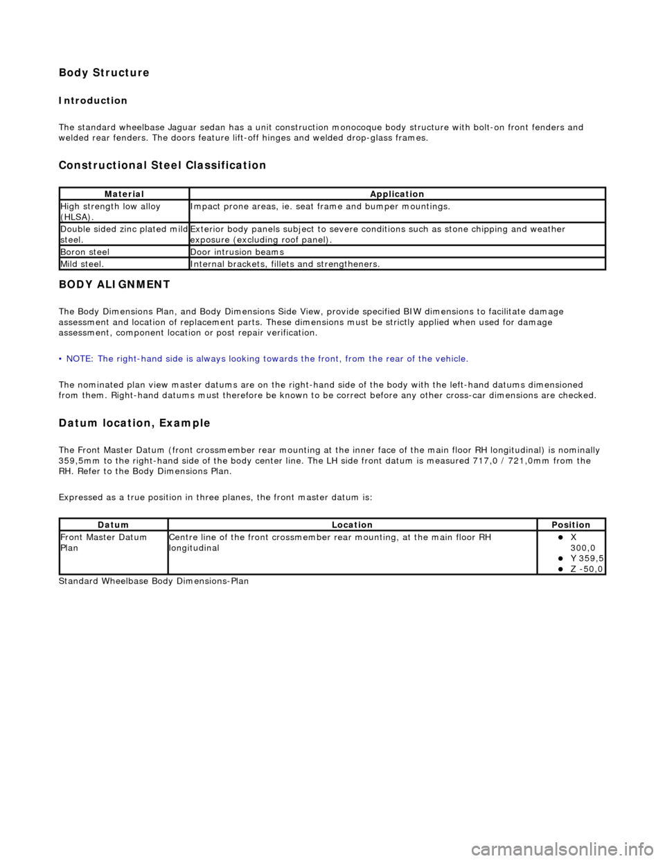
The standard wheelbase Jaguar sedan has a unit construction monocoque body structure with bolt-on front fenders and
welded rear fenders. The doors feature lif t-off hinges and welded drop-glass frames.
Constructional Steel Classification
BODY ALIGNMENT
The Body Dimensions Plan, and Body Dimensions Side View, provide specified BIW dimensions to facilitate damage
assessment and location of replacemen t parts. These dimensions must be strictly applied when used for damage
assessment, component location or post repair verification.
• NOTE: The right-hand side is always looking towards the front, from the rear of the vehicle.
The nominated plan view master datums are on the right-hand side of the body with the left-hand datums dimensioned
from them. Right-hand datums must therefore be known to be correct before any other cross-car dimensions are checked.
Datum location, Example
The Front Master Datum (front crossmember rear mounting at the inner face of the main floor RH longitudinal) is nominally
359,5mm to the right-hand side of the body center line. The LH side fron t datum is measured 717,0 / 721,0mm from the
RH. Refer to the Body Dimensions Plan.
Expressed as a true posi tion in three planes, the front master datum is:
Standard Wheelbase Bo dy Dimensions-Plan
MaterialApplication
High strength low alloy
(HLSA).Impact prone areas, ie. seat frame and bumper mountings.
Double sided zinc plated mild steel.Exterior body panels subject to severe cond itions such as stone chipping and weather
exposure (excluding roof panel).
Boron steelDoor intrusion beams
Mild steel.Internal brackets, fill ets and strengtheners.
DatumLocationPosition
Front Master Datum
PlanCentre line of the front crossmember rear mounting, at the main floor RH
longitudinalX
300,0
Y 359,5 Z -50,0
Page 2387 of 2490
Key to Plan
Standard Wheelbase Body Dimensions- Side View
KeyLocation
1Front face body-bumper strut/mounting point
2Rearmost hole, vee-mount to crush tube
3Front Master Datum Plan, centre li ne of front crossmember rear mount ing at main floor RH longitudinal
4Rearmost hole, transmission mounting at main floor RH longitudinal
5Handbrake rear lever bracket fixings
6Rear Master Datum Plan, rear longitudinal
7Tapped boss, rear suspension 'A' frame mounting bush
8Rear suspension spring-pan damper mounting
9Rear suspension differential strut mounting
10Rear face body-bumper strut/mounting point
11Driveshaft centre bearing mounting
Page 2388 of 2490
Key to SideView
Long Wheelbase Body Dimensions-Plan
KeyLocation
1Front face body-bumper strut/mounting point
2Front Master Datum Vertical, centre line of front crossmember rear mounting
3Transmission mountings at the main floor longitudinal
4Handbrake rear lever bracket fixings
5Rear Master Datum Vertical,, rear longitudinal
6Tapped boss, rear suspensi on 'A' frame mounting bush
7Rear suspension spring-pan damper mounting
8Rear suspension differential strut mounting
9Rear face body-bumper strut/mounting point
10Wheel centre to bumper cover face
11Wheelbase
12Wheel Centre to Bumper Cover Face
13Driveshaft centre bearing mounting
Page 2389 of 2490
Key to Plan
Long Wheelbase Body Dimensions- Side View
KeyLocation
1Front face body-bumper strut/mounting point
2Rearmost hole, vee-mount to crush tube
3Front Master Datum Plan, centre line of front crossmember rear mount ing at main floor RH longitudinal
4Rearmost hole, transmission mounting at main floor RH longitudinal
5Handbrake rear lever bracket fixings
6Rear Master Datum Plan, rear longitudinal
7Tapped boss, rear suspension 'A' frame mounting bush
8Rear suspension spring-pan damper mounting
9Rear suspension differential strut mounting
10Rear face body-bumper strut/mounting point
11Driveshaft centre bearing mounting
Page 2390 of 2490
Key to SideView
KeyLocation
1Front face body-bumper strut/mounting point
2Front Master Datum Vertical, centre line of front crossmember rear mounting
3Transmission mountings at the main floor longitudinal
4Handbrake rear lever bracket fixings
5Rear Master Datum Vertical,, rear longitudinal
6Tapped boss, rear suspensi on 'A' frame mounting bush
7Rear suspension spring-pan damper mounting
8Rear suspension differential strut mounting
9Rear face body-bumper strut/mounting point
10Wheel centre to bumper cover face
11Wheelbase
12Wheel Centre to Bumper Cover Face
13Driveshaft centre bearing mounting
Page 2421 of 2490

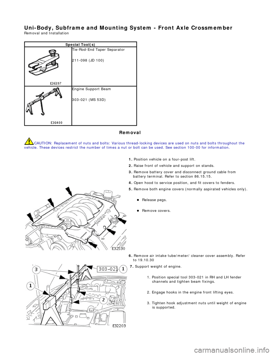
Uni-Body, Subframe and Mounting System - Front Axle Crossmember
Removal and Installation
Removal
CAUTION: Replacement of nuts and bolts: Various thread-locking devices are used on nuts and bolts throughout the
vehicle. These devices restrict the number of times a nut or bolt can be used. See section 100-00 for information.
Special Tool(s)
Tie-Rod-End Taper Separator
211-098 (JD 100)
Engine Support Beam
303-021 (MS 53D)
1. Position vehicle on a four-post lift.
2. Raise front of vehicle and support on stands.
3. Remove battery cover and disc onnect ground cable from
battery terminal. Refer to section 86.15.15.
4. Open hood to service position, and fit covers to fenders.
5. Remove both engine covers (nor mally aspirated vehicles only).
Release pegs.
Remove covers.
6. Remove air intake tube/meter/ cleaner cover assembly. Refer
to 19.10.30
7. Support weight of engine.
1. Position special tool 303-021 in RH and LH fender channels and tighte n beam fixings.
2. Engage hooks in the en gine front lifting eyes.
3. Tighten hook adjustment nuts until weight of engine is supported.
Page 2426 of 2490
32. From engine compartment, remove crossbeam front LH
securing bolts.
33. Remove crossbeam to engine Hydramount securing bolts.
Remove bolt securing cros smember to Hydramount.
Fully withdraw bolt into crossmember insert.
Repeat procedure to remove and withdraw bolt on
opposite side
34. CAUTION: To prevent damage to ball joints, secure
each hub assembly to suspensi on turret using strong wire.
Remove lower nut and bolt from front shock absorber.
Repeat procedure to remove bo lt from opposite side shock
absorber.
35. Remove crossbeam rear securing bolts.
Remove bolt from crossbeam LH rear mounting.
Repeat procedure to remove bolt from crossbeam RH rear
mounting.
Page 2434 of 2490
Repeat procedure to install opposite side shock absorber.
21. Install lower steering column on pinion shaft.
Move column downwards to engage coupling splines on
pinion shaft.
1. Install nut and bolt and tighten to 22-28Nm.
22. Lower and withdraw jack from crossbeam.
23. Release engine from support tool.
1. Slacken hook adjustment nuts until weight of engine is released.
2. Remove hooks from engine front lifting eyes.
3. Remove special tool 303- 021 from fender channel.
24. Install crossbeam to engine Hydramount securing bolts.
Install bolt securing Hydr amount to crossmember and
tighten to 22-28Nm.
Repeat procedure to install crossmember opposite side
securing bolt.
25. Position and connect harnes s to steering transducer.
RHD vehicles. Position steeri ng harness behind return
pipe.
Connect harness to transducer.