Page 1394 of 2490

Range Selection
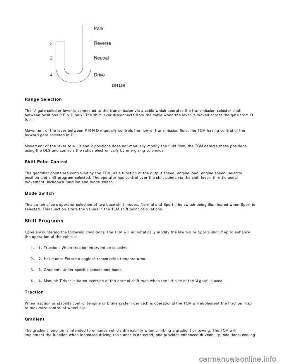
The 'J' gate selector lever is connected to the transmission via a cable which operates the transmission selector shaft
between positions P R N D only. The shift lever disconnects from the cable when the lever is moved across the gate from D
to 4 .
Movement of the lever between P R N D manu ally controls the flow of transmission fluid, the TCM having control of the
forward gear selected in D .
Movement of the lever to 4 , 3 and 2 positions does not manu ally modify the fluid flow, the TCM detects these positions
using the DLS and controls the ratios electronically by energizing solenoids.
Shift Point Control
The gearshift points are controlled by the TCM, as a function of the output speed, engine load, engine speed, selector
position and shift program selected. The operator has control over the shift points via the shift lever, throttle pedal
movement, kickdown function and mode switch.
Mode Switch
This switch allows operator selection of two base shift modes; Normal and Sport; th e switch being illuminated when Sport is
selected. This function alters the values in the TCM shift point calculations.
Shift Programs
Upon encountering the following conditions, the TCM will auto matically modify the Normal or Sports shift map to enhance
the operation of the vehicle:
1. 1. Traction: When traction intervention is active.
2. 2. Hot mode: Extreme engine/transmission temperatures.
3. 3. Gradient: Under specific speeds and loads.
4. 4. Manual: Driver initiated override of the normal shif t map when the LH side of the 'J gate' is used.
Traction
When traction or stability control (engine or brake system de rived) is operational the TCM will implement the traction map
to maximize control of wheel slip.
Gradient
The gradient function is intended to enhance vehicle drivea bility when climbing a gradient or towing. The TCM will
implement the function when increased driving resistance is de tected, and provides enhanced driveability, additional cooling
Page 1462 of 2490
Transmission/Transaxle Cooling - 4.0L NA V8 - AJ27/3.2L NA V8 - AJ26 -
Transmission Cooling
Description and Operation
The transmission fluid cooling system maintains fluid temperature within specified limits.
Parts List
Component Descriptions
The transmission fluid pipes:
Transfer fluid from the transmission to the cooler under the action of the hydraulic system pump. Return the cooled fluid from th e cooler to the transmission.
The transmission fluid cooler:
Is a plate type made from aluminum. Is mounted in the engi ne cooling radiator right-hand end tank.
Overheating Protection
If the engine coolant or transm ission fluid temperatures exceed their predefined limits, th e transmission control module locks
the torque converter clutch. By reducing slip, this minimises th e amount of heat transferred to the engine cooling system from
the transmission fluid.
ItemPart NumberDescription
1—Fluid pipe, oil FROM cooler
2—Fluid pipe, oil TO cooler
Page 1463 of 2490
Transmission/Transaxle Cooling - 4.0L SC V8 - AJ26 - Transmission
Cooling
Description and Operation
The transmission fluid cooling system maintains the fluid temperature within specified limits. The cooling element is located
in the engine cooling radiator LH end tank.
Fluid is circulated, under pressure, by the transmission pump to the cooler.
General Layout
Overheating Protection
If the engine coolant or transmission fluid temperatures exceed their predefined limits, the transmission control module
locks the torque converter clutch . By reducing slip, this minimises the amount of heat transferred to the engine cooling
system from the transmission fluid.
Page 1546 of 2490
Connect the scan tool 1
Have the DTC(s) and freeze frame data been recorded?
Yes GO to B2
B2: CHECK FOR LOW EX HAUST TEMPERATURE
Check the engine and exhaust system for normal running
temperature 1
Is the engine and exhaust sy stem up to normal running
temperature?
Yes GO to B3
No Rectify possible leaking exhaust manifold / catalyst, general
causes of an over rich mixture and engine cooling system
operation. Test the system for correct operation.
GO to B8
B3: CHECK FOR O2 SENS OR HEATER CONTINUITY
Ignition switch to position 0 1
Disconnect EM021
Bracket on top of gearbox or Bulkhead rear of engine
2
With EM021 disconnected, measure the resistance between
EM021/001 and EM021/002. 3
Is the resistance between 4 and 10 OHM?
Yes
GO to B4
No Renew O2 sensor, reconnect plug(s).
GO to B8
B4: CHECK FOR O2 SENSOR FAILURE
Page 1570 of 2490
Connect the scan tool 1
Have the DTC(s) and freeze frame data been recorded?
Yes GO to D2
D2: CHECK FOR LOW EXHAUST TEMPERATURE
Check the engine and exhaust system for correct operation
and normal running temperature 1
Is the engine and exhaust system operating correctly and up to
normal running temperature?
Yes GO to D3
No Rectify leaking exhaust manifold / catalyst, general causes of
an over rich mixture and engine cooling system operation
and test the system for correct operation.
GO to D7
D3: CHECK FOR O2 SENSOR FAILURE
Run the engine for a period to warm the sensor and then
maintain a steady speed of approximately 2500 rpm. 1
Measure the voltage between EM022/001 and EM022/002. 2
Page 1598 of 2490
Connect the scan tool 1
Have the DTC(s) and freeze frame data been recorded?
Yes GO to F2
F2: CHECK FOR LOW EXHAUST TEMPERATURE
Check the engine and exhaust system for normal running
temperature 1
Is the engine and exhaust sy stem up to normal running
temperature?
Yes GO to F3
No Rectify possible leaking exhaust manifold / catalyst,
general causes of an over ri ch mixture and engine cooling
system operation. Test the sy stem for correct operation.
GO to F8
F3: CHECK FOR O2 SENSOR HEATER CONTINUITY
Ignition switch to position 0 1
Disconnect EM023
Bracket on top of gearbox or Bulkhead rear of engine
2
Measure the resistance between EM023/001 and
EM023/002. 3
Is the resistance between 4 and 10 OHM?
Yes
GO to F4
No Renew O2 sensor. Reconnect plug(s).
GO to F8
F4: CHECK FOR O2 SENSOR FAILURE
Page 1625 of 2490
Conne
ct the scan tool
1
Have the DTC(s) and fr
eeze
frame data been recorded?
Yes GO to H2
H2: CHECK
FOR LOW EXHAUST TEMPERATURE
Chec
k the engine and exhaust
system for correct operation
and normal running temperature
1
Is th
e engine and exhaust system operating correctly and up to
normal running temperature?
Yes GO to H3
No Rectify leaking exhaust manifold / catalyst, general causes of
an over rich mixture and engine cooling system operation and
test the system for correct operation.
GO to H7
H
3: CHECK FOR O2 SENSOR FAILURE
I
gnition switch to position 0
1
Di
sconnect EM024
Bracket on top o
f gearbox or
Bulkhead rear of engine
2
R
un the engine for a period to
warm the sensor and then
maintain a steady speed of approximately 2500 rpm.
3
W
ith EM024 disconnected, measure the voltage between
EM024/001 and EM024/002.
4
Is
the voltage between 600mV and 1.0 Volt?
Yes GO to H4
No Renew O2 sensor. Reconnect plug(s).
GO to H7
H
4: CHECK FOR O2 SENSOR FAILURE
Page 1756 of 2490

Probable
causes of faults may be found by comparing actual
system pressures, registered on your manifold gauge set or
recovery / recharge / recycle station, and the relevant pressure to temperature relationship graph. The following chart
shows the interpretation that ma y be made by this difference.
• NOTE: The A/CCM will disengage the compressor clutch should the evaporator temperature fall to 0°C.
• NOTE: Graphs are typical for HFC 134A
The 'Normal' condition is that which is relevant to the prevailing evaporator temperature.
System Pressure Fault Classification
• NOTE
: If erratic or unusual gauge move
ments occur, check the equipment against a known (calibrated) manifold gauge
set.
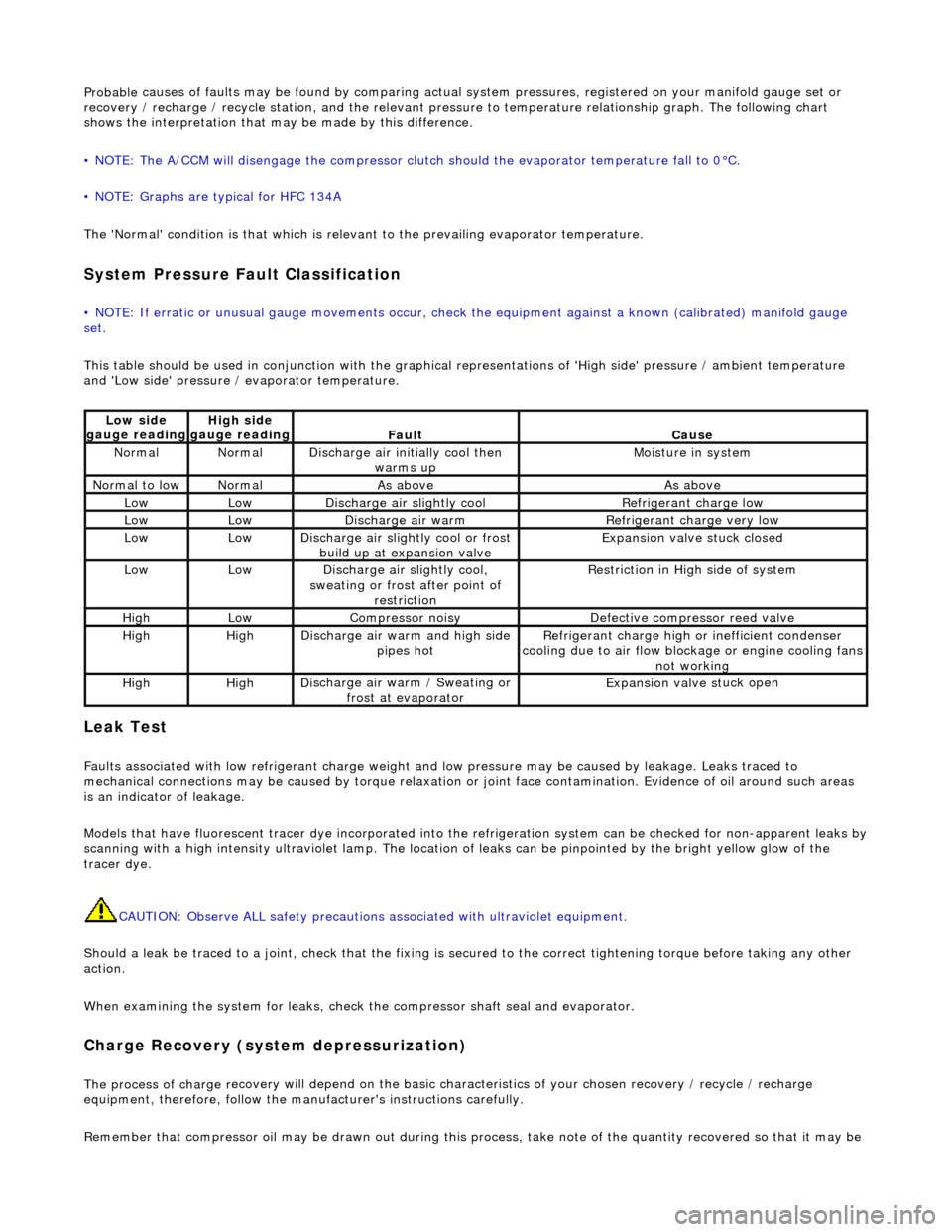
This table should be used in conjunction with the graphical representations of 'High side' pressure / ambient temperature
and 'Low side' pressure / evaporator temperature.
Leak
Test
F
a
ults associated with low re
frigerant charge weight and low pressure ma y be caused by leakage. Leaks traced to
mechanical connections may be caused by to rque relaxation or joint face contamination. Evidence of oil around such areas
is an indicator of leakage.
Models that have fluorescent tracer dye incorporated into the refrigeration system can be checke d for non-apparent leaks by
scanning with a high intensity ultraviolet lamp. The location of leaks can be pinpointed by the bright yellow glow of the
tracer dye.
CAUTION: Observe ALL safety precautions associated with ultraviolet equipment.
Should a leak be traced to a joint, check that the fixing is secured to the correct tightening torque before taking any other
action.
When examining the system for leaks, chec k the compressor shaft seal and evaporator.
Charge Re
covery (system depressurization)
The process of
charge r
ecovery will depe
nd on the basic characteristics of your chosen recovery / recycle / recharge
equipment, therefore, follow the manu facturer's instructions carefully.
Remember that compressor oil may be drawn out during this process, take note of the quantity recovered so that it may be
Lo
w side
gauge reading
High s i
de
gauge reading
Fau l
t
Cause
No
r
mal
No
r
mal
Di
sc
harge air initially cool then
warms up
Mois
ture in system
N
ormal
to low
No
r
mal
As aboveAs above
LowLowD
i
scharge air slightly cool
Ref
r
igerant charge low
LowLowDi
scharge air warm
Refr
igerant charge very low
LowLowDi
scharge air slightly cool or frost
build up at expansion valve
Expansion valve st
uck closed
LowLowDi
scharge air slightly cool,
sweating or frost after point of restriction
Restri
ction in High side of system
HighLowCompressor noisyDe
fe
ctive compressor reed valve
HighHighD
i
scharge air warm and high side
pipes hot
Refri
gerant charge high or inefficient condenser
cooling due to air flow blockage or engine cooling fans
not working
HighHighD i
scharge air warm / Sweating or
frost at evaporator
Expans ion valve st
uck open