1998 JAGUAR X308 suspension
[x] Cancel search: suspensionPage 247 of 2490

20
.
Remove nuts and withdraw special tool (204-195) from hub.
21. Install rear wheel. Refer to Section 204-04.
22. Remove stands and lower vehi cle onto wheels. Refer to
section 100-02.
23. Raise vehicle on four-post lift.
24
.
Route parking brake cable through suspension mounting
bracket and secure with clip.
25
.
Route parking brake cable through equalizer (LH side cable
only).
26
.
Install parking brake cabl e in connecting clip.
27. Adjust parking brake cable. Refer to 70.35.10.
28. Lower four-post lift
29. Apply parking brake.
30. Carry out rear wheel alignm ent check and adjust as
necessary. Refer
t
o 204-02 Specification section.
Page 251 of 2490

19
.
Install a thread protector on axle shaft.
20
.
Release hub from axle shaft.
Position hu
b puller on hub studs. (204-011)
Inst
all securing nuts.
Progres
sively tighten
puller center bolt to release hub from
axle shaft splines.
21. Remove nuts and release puller from hub.
22. Remove thread protec tor from axle shaft.
23
.
Release handbrake cable from suspension mounting bracket.
Remove cable reta
ining clip.
Draw c
able through suspension mounting bracket
aperture.
24. Remove parking brake cable to hub carrier grommet.
Page 267 of 2490

The
following explanations will help isolate the source of vibration.
Torque Sensitive
This
means that the condition can be impr
oved or made worse by accelerating, dece lerating, coasting, maintaining a steady
vehicle speed, or applying engine torque.
Ve
hicle Speed Sensitive
This means th
at the vibration al
ways occurs at the same vehicle speed and is not affected by engine torque, engine speed
or gear selection.
Engine Speed Sensit
ive
This means th
at the vibration
occurs at varying vehicle spee ds when a different gear is selected. It can sometimes be
isolated by increasing or decreasing engine speed with the tran smission in neutral or by stall testing with the transmission in
gear. If the condition is engine speed sensitive, the cause is probably not related to tires.
If the road test indicates that there is tire wine, but no shake or vibration, the noise originates with the contact between th e
tire and the road surface.
A thumping noise usually means that the tire is flat or has soft spots making a noise as they slap the roadway. Tire whine
can be distinguished from axle no ise, as tire whine remains the same over a range of speeds.
Sym
ptom Chart
Sy
mptom Chart
Sy
mptom
Possib
le Sources
Acti
on
Uneven ti
re wear.
Incorrect ti
re inflation.
*
Cor
rect to specification.
*
Exce
ssive radial an
d lateral runout.
*
Renew tire
or wheel.
*
O
ut of specification steering
geometry.
*
R
ealign steering geometry: Refer to Section 204-
00.
*
W
orn ball joint.
*
Renew
damaged component, realign steering
geometry.
*
W
orn tie-rod end.
*
R
enew component, realign steering geometry.
*
Incorrect
tire / wheel usage.
*
Inst
all correct tire and wheel combination.
*
Loose or leaki
ng shock absorbers.
*
Tigh
ten or Renew as nece
ssary: Refer to Section
204-00.
*
Suspensi
on geometry out of
alignment.
*
Che
ck and adjust: Refer to Section 204-00.
*
Loose, worn or da mage
d suspension
components.
*
In
spect, Repair or Renew as necessary.
*
Wh
eel and tire assembly out of
balance.
*
Balance wheel an
d tire assembly.
*
Excessive later
al or radial runout of
wheel or tire.
*
Check, Repair o
r
Renew as required.
*
Tire
s show excess wear on
edge of treads.
Ti
res under-inflated.
*
Cor
rect pressure to specification.
*
Vehi
cle overloaded.
*
Cor
rect to specification.
*
Tire
s show excess wear on
edge of treads (with tire
pressures correct).
Incorre
ct toe setting.
*
Se
t to specification: Refer to Section 204-00.
*
Tire
s show excess wear in
center of tread.
Tire
s over-inflated.
*
Cor
rect pressure to specification
*
W
heel mounting is
difficult.
Incorrect app
lication or mismatched
parts, including wheel studs and
wheel nuts. Corroded, worn or
damaged parts.
*
Fol
low the manufacturer's specifications. Clean or
Renew.
*
Wobble or sh
immy
affecting wheel runout.
Damaged wh
eel (eventually
damaging wheel bearings and causing
uneven tire wear).
*
Inspect wheel rims for
damage and runout. Renew
as required.
*
Vehicle vibrations from
Tire
s / wheels mismatched.
*
Inst
all correct tire / wheel combination.
*
Page 271 of 2490

Vehicle Dynamic Suspension - Vehicle Dynamic Suspension
Description an
d Operation
Front Sho
ck Absorbers
The front shock absorber
comprises:
A
coil-type road spring, mounted between the lower wish
bone spring pan and the front suspension crossbeam;
different spring rates are used according to model.
A
telescopic, hydraulically controlled, damper mounte
d between the lower wishbone and the vehicle body.
It
em
De
scription
1Front
suspension crossbeam
2Front
hub assembly
3Ro
ad spring
4Dam
per
Page 273 of 2490

The
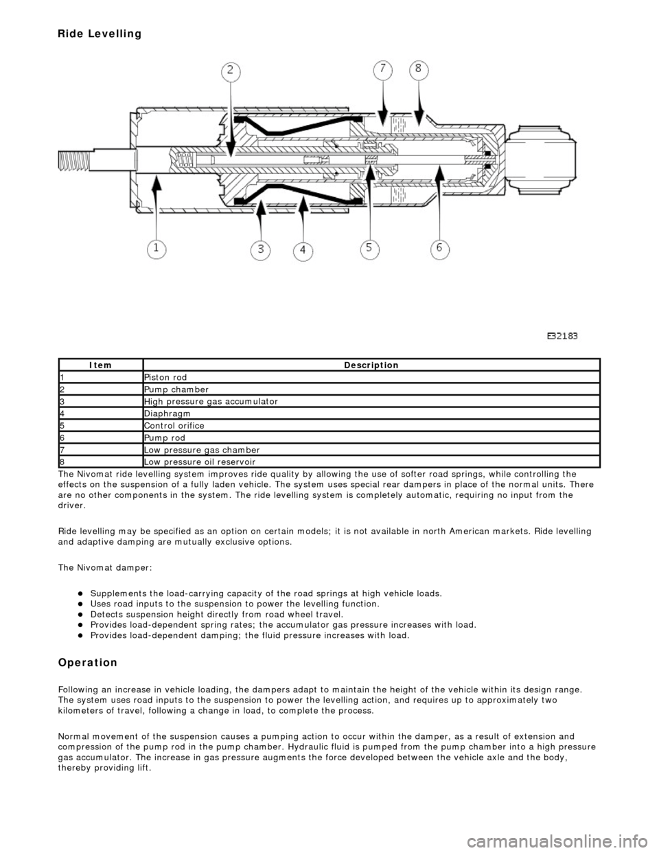
Nivomat ride levelling system improves ride quality by al
lowing the use of softer road springs, while controlling the
effects on the suspension of a fully laden vehicle. The system uses special rear dampers in place of the normal units. There
are no other components in th e system. The ride levelling system is comple tely automatic, requiring no input from the
driver.
Ride levelling may be specified as an opti on on certain models; it is not available in north American markets. Ride levelling
and adaptive damping are mu tually exclusive options.
The Nivomat damper:
Su
pplements the load-carrying capacity of th
e road springs at high vehicle loads.
Uses road inputs to the
suspension to power the levelling function.
De
tects suspension height dire
ctly from road wheel travel.
Provi
des load-dependent spring rates; the ac
cumulator gas pressure increases with load.
Pr
ovides load-dependent damping; the fluid pressure increases with load.
Op
eration
F
ollowing an increase in vehicle loading,
the dampers adapt to maintain the height of the vehicle within its design range.
The system uses road inputs to the suspension to power the levelling action, and requires up to approximately two
kilometers of travel, following a change in load, to complete the process.
Normal movement of the suspension caus es a pumping action to occur within the damper, as a result of extension and
compression of the pump rod in the pump chamber. Hydraulic fluid is pumped from the pump cham ber into a high pressure
gas accumulator. The increase in gas pressure augments the force developed between th e vehicle axle and the body,
thereby providing lift.
It
em
De
scription
1Pi
ston rod
2Pum
p chamber
3High
pressure
gas accumulator
4Diaphragm
5Co
ntrol orifice
6Pump rod
7Low pressure gas ch
amber
8Low pressure oil
reservoir
Ride Levelling
Page 276 of 2490

Is hard-wi
red to the instrume
nt cluster message center.
Is hard
-wired to the J1962 diagnostic connector.
Op
era
tion
Th
e
system selects the soft or
firm damper setting according to the current ro ad and driving conditions, to optimise vehicle
ride and handling.
With the vehicle stationary, the dampers are in the firm setting, but will normally switch to the soft setting when the vehicle
exceeds 8 km/h (5 mile/h); all dampers are switched simultaneously.
Sudden movement of the vehicle body, in response to road inputs, is detected by the vertical accelerometers, and the ADCM
switches the dampers to the firm setting to give improved damping of the resultant oscillations.
When cornering forces are detected by th e lateral accelerometer, the ADCM switches the dampers to the firm setting to
reduce the roll rate an d improve wheel control.
After the event has passed, the dampers revert to the soft setting.
When the footbrake is applied, the ADCM re ceives a signal and calculates the rate of vehicle deceleration. If the deceleration
rate is greater than a certain threshold, the dampers are switched to the firm setting to reduce the pitch rate and improve
wheel control.
If a system failure occurs, the ADCM grounds the output line to the instrument cluster message center, which displays a
text warning SUSPENSION FAULT and illuminates the amber warning lamp. Under fault conditions the system always fails to
the firm setting, so that the vehicle will be safe to drive un der all road and driving conditions.
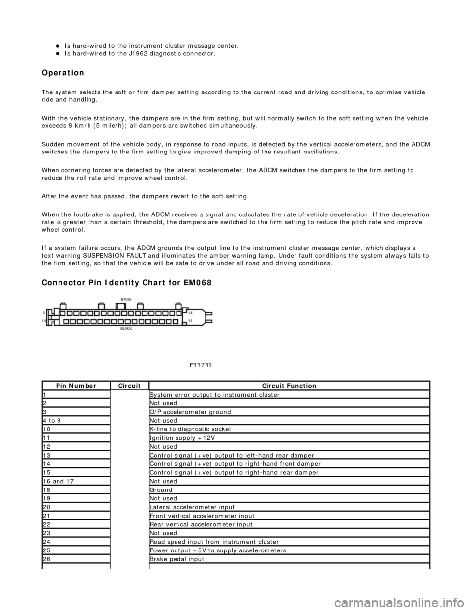
Connector Pin Identity Chart for EM068
Pin
Number
Ci
rcui
t
Circuit Functi
on
1System erro
r output to instrument
cluster
2Not
used
3O/
P a
ccelerometer ground
4 to
9
Not
used
10K-
li
ne to diagnostic socket
11Ignition su
pply +12V
12Not
used
13Control signal (+ve) output
to l
eft-hand rear damper
14Control signal (+ve) output
to right-hand front damp
er
15Control signal (+ve) output
to right-hand rear
damper
16
a
nd 17
No
t
used
18Ground
19No
t
used
20Lateral
accelerometer i
nput
21Front vertical ac
celerometer in
put
22Rear vertical
acce
lerometer input
23No
t
used
24R
o
ad speed input from
instrument cluster
25Power output +5V to suppl y accelerometers
26Brake peda
l input
Page 278 of 2490

Vehicle Dynamic Suspension - Vehicle Dynamic Suspension
Diagn
osis and Testing
Refer to the PDU User Guide for details of diagnosing and testing the Adaptive Damping System. The PDU interrogates the
ADCM directly via the K and L lines to the J1962 diagnostic socket.
The PDU will give an indication of the integrity of each electron ic and electrical component. It will indicate, for example, that
the accelerometers are not broken, but not that they functionin g correctly when the vehicle is in motion. However, it is
exceptional for an accelero meter to function incorrectly in its dynamic mode if it is proved to be functioning when static.
Basic Checks
The accele
rometers have the following ch
aracteristics. At 0g (no movement of the body) each vertical accelerometer
outputs approximately 2.5V steady voltage; the lateral acce lerometer outputs approximately 1.5V. The voltage output due
to body movement is proportional to acceleration in the acceleration axis, up to approximately 4.5V and down to
approximately 0.5V.
Before changing any component, refer to the circuit diagrams and check the cont inuity of relevant harness circuits; in some
instances, the PDU will not different iate between a faulty component an d a damaged connection or wiring.
Check the following fuses:
En
gine compartment fuse
box, fuse F5 (10A).
Engine m
anagement fuse
box, fuse F1 (20A).
Check the following ADCM input/output lines:
Sy stem erro
r output from the ADCM
to the instrument cluster.
Vehicl
e speed output from the inst
rument cluster to the ADCM.
Foo
tbrake signal to the ADCM.
Check any relevant connections to confirm that the connection is electrically sound and that a terminal pin has not been
pushed back into the connector shell, ie. not ma king a connection to its mating pin or socket.
Page 309 of 2490

Brake System - General Inform
ation - Brake System
D
iagnosis and Testing
Principles of Operations
The brake system operates by transferring effort applied to th e brake pedal, by the driver to the brakes at each wheel.
The braking effort is distributed to each wheel, using a hydraulic system. The system is assisted using a vacuum brake
booster that reduces pedal effort for a given hydraulic pressure. The parking brake operates on the rear wheels and is
applied using a hand operated control.
I
nspection and Verification
•
NOTE: Prior to carrying out any diagno
sis, make sure that the brake system warning indicator is functional.
Visually examine the front and rear tire and wheel assemblies for damage such as un even wear patterns, tread worn out or
sidewall damage. Verify the tires are th e same size, type and, where possible, same manufacture. Replace the damaged
wheel or excessively worn tire. For a dditional information, refer toSection 204
-0
4 Wheels and Tires
.
W
heels and tires must be cleared of an
y foreign matter and tire pressures ad justed to the correct specification.
If the tires exhibit uneven wear or feathering, the cause must be corrected. Check the steering and suspension components
for damage or wear and, if ne cessary, check and adjust front wheel alignment. For additional information, refer toSection
204
-00 Suspen
sion System
- General Informati
on
.
Road Test
V
isual Inspection Chart
Carr
y out a road test to compare actual vehicle braking performance with the
performance standards expected by the
driver. The ability of the test driver to make valid compar isons and detect performance deficiencies will depend on
experience.
The driver should have a thorough knowledge of brake system operation and accepted general performance guidelines to
make good comparisons and de tect performance concerns.
An experienced brake technician will always establish a route that will be used for all br ake diagnosis road tests. The roads
selected will be reasonably smooth and level. Gravel or bump y roads are not suitable because the surface does not allow the
tires to grip the road equally. Crowned roads should be avoide d because of the large amount of weight shifted to the low set
of wheels on this type of road. Once th e route is established and consistently used, the road surface variable can be
eliminated from the test results.
Before a road test, obtain a complete description of the customer concerns or suspec ted condition. From the description, the
technician's experience will allow the te chnician to match possible causes with symptoms. Certain components will be
tagged as possible suspects while others wi ll be eliminated by the evidence. More importantly, the customer description can
reveal unsafe conditions which should be ch ecked or corrected before the road test. The description will also help form the
basic approach to the road test by narrowing the concern to specific components, vehicle speed or conditions.
Begin the road test with a general brake performance check. Keeping the description of the concern in mind, test the brakes
at different vehicle speeds using both ligh t and heavy pedal pressure. To determine if the concern is in the front or rear
braking system, use the brake pe dal and then use the parking brake control. If the condition (pull, vibration, pulsation)
MechanicalElectrical
Brake m
aster cylinder
Parkin
g brake switch
Brake ca
liper piston(s)
D
amaged or corroded wiring harness
Brake di
scs
B
rake master cylinder fluid level switch
Wh
eel bearin
gs
Brake pads
Power brake booster
Brake ped
al linkage
Boost
er vacuum hose
Tire
s
De
bris