1998 ISUZU TROOPER air
[x] Cancel search: airPage 4 of 3573

PAGE BACK PAGE NEXT
THIS MALUAL INCLUDES THE FOLLOWING SECTIONS:
SECTION No. CONTRNTS
00 SERVICE INFORMATION
1A HEATING AND VENTILATION
1B AIR CONDITIONING
1D COMPRESSOR OVERHAUL
Page 15 of 3573

GENERAL INFORMATION 0AÐ1
SECTION 0A
GENERAL INFORMATION
CONTENTS
PAGE
General Repair Instructions...............................................0AÐ 2
How To Use This Manual.................................................0AÐ 3
Identification...........................................................0AÐ 6
Lifting Instructions......................................................0AÐ 8
Torque Specifications....................................................0AÐ10
Recommended Liquid Gasket.............................................0AÐ11
Recommended Thread Locking Agents.....................................0AÐ11
Abbreviations Charts....................................................0AÐ12
Service Precaution
WARNING: THIS VEHICLE HAS A SUPPLEMENTAL
RESTRAINT SYSTEM (SRS). REFER TO THE SRS
COMPONENT AND WIRING LOCATION VIEW IN
ORDER TO DETERMINE WHETHER YOU ARE
PERFORMING SERVICE ON OR NEAR THE SRS
COMPONENTS OR THE SRS WIRING. WHEN YOU
ARE PERFORMING SERVICE ON OR NEAR THE
SRS COMPONENTS OR THE SRS WIRING, REFER
TO THE SRS SERVICE INFORMATION. FAILURE
TO FOLLOW WARNINGS COULD RESULT IN
POSSIBLE AIR BAG DEPLOYMENT, PERSONAL
INJURY, OR OTHERWISE UNNEEDED SRS
SYSTEM REPAIRS.CAUTION: Always use the correct fastener in the
proper location. When you replace a fastener, use
ONLY the exact part number for that application.
ISUZU will call out those fasteners that require a
replacement after removal. ISUZU will also call out
the fasteners that require thread lockers or thread
sealant. UNLESS OTHERWISE SPECIFIED, do not
use supplemental coatings (Paints, greases, or
other corrosion inhibitors) on threaded fasteners
or fasteners joint interfaces. Generally, such
coatings adversely affect the fastener torque and
the joint clamping force, and may damage the
fastener. When you install fasteners, use the
correct tightening sequence and specification.
Following these instructions can help you avoid
damage to parts and systems.
Page 16 of 3573
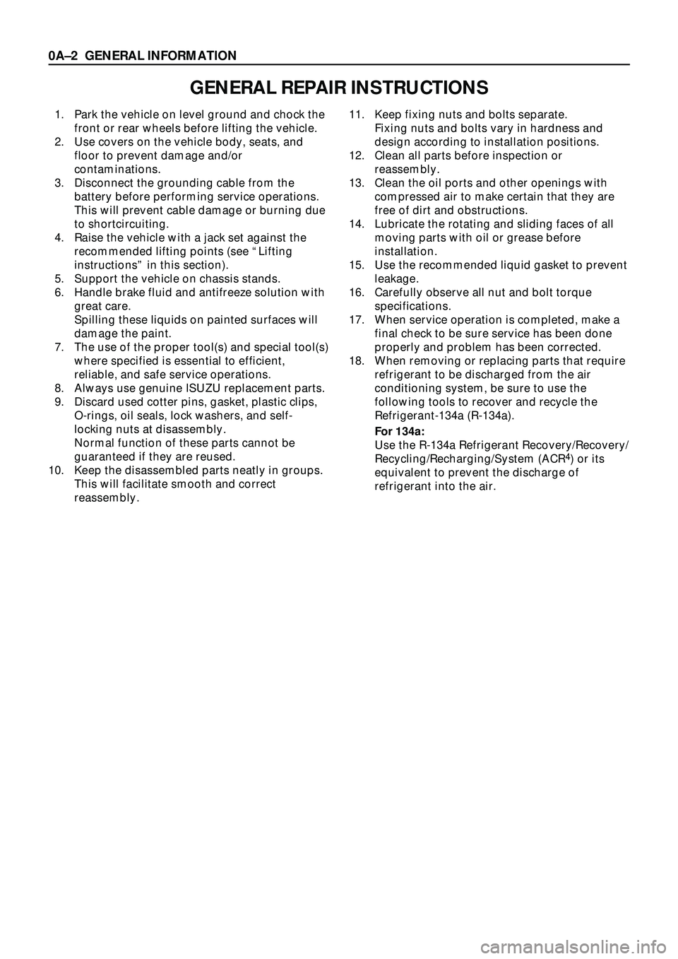
GENERAL REPAIR INSTRUCTIONS
1. Park the vehicle on level ground and chock the
front or rear wheels before lifting the vehicle.
2. Use covers on the vehicle body, seats, and
floor to prevent damage and/or
contaminations.
3. Disconnect the grounding cable from the
battery before performing service operations.
This will prevent cable damage or burning due
to shortcircuiting.
4. Raise the vehicle with a jack set against the
recommended lifting points (see ÒLifting
instructionsÓ in this section).
5. Support the vehicle on chassis stands.
6. Handle brake fluid and antifreeze solution with
great care.
Spilling these liquids on painted surfaces will
damage the paint.
7. The use of the proper tool(s) and special tool(s)
where specified is essential to efficient,
reliable, and safe service operations.
8. Always use genuine ISUZU replacement parts.
9. Discard used cotter pins, gasket, plastic clips,
O-rings, oil seals, lock washers, and self-
locking nuts at disassembly.
Normal function of these parts cannot be
guaranteed if they are reused.
10. Keep the disassembled parts neatly in groups.
This will facilitate smooth and correct
reassembly.11. Keep fixing nuts and bolts separate.
Fixing nuts and bolts vary in hardness and
design according to installation positions.
12. Clean all parts before inspection or
reassembly.
13. Clean the oil ports and other openings with
compressed air to make certain that they are
free of dirt and obstructions.
14. Lubricate the rotating and sliding faces of all
moving parts with oil or grease before
installation.
15. Use the recommended liquid gasket to prevent
leakage.
16. Carefully observe all nut and bolt torque
specifications.
17. When service operation is completed, make a
final check to be sure service has been done
properly and problem has been corrected.
18. When removing or replacing parts that require
refrigerant to be discharged from the air
conditioning system, be sure to use the
following tools to recover and recycle the
Refrigerant-134a (R-134a).
For 134a:
Use the R-134a Refrigerant Recovery/Recovery/
Recycling/Recharging/System (ACR
4) or its
equivalent to prevent the discharge of
refrigerant into the air.
0AÐ2 GENERAL INFORMATION
Page 17 of 3573
GENERAL INFORMATION 0AÐ3
HOW TO USE THIS MANUAL
1. Find the applicable section by referring to the
table of contents on the introduction page of
each manual.
2. In ÒService InformationÓ, an opening section of
each manual, the troubleshooting, maintenance
servicing, service data and/or information on
special tools required for the service operations
described in the next subsequent sections are
arranged and compiled so concisely that you
can see at a first glance.
3. Each section except the Service Information
section is basically arranged in the following
order of headings:
General description
On-vehicle service
Unit repair4. The service operations are in two groups: one is
the ÒOn-vehicle serviceÓ where operations can
be directly performed on the vehicle, and the
other is the ÒUnit repairÓ where the operations
are done on the work bench after removing the
unit from the vehicle.
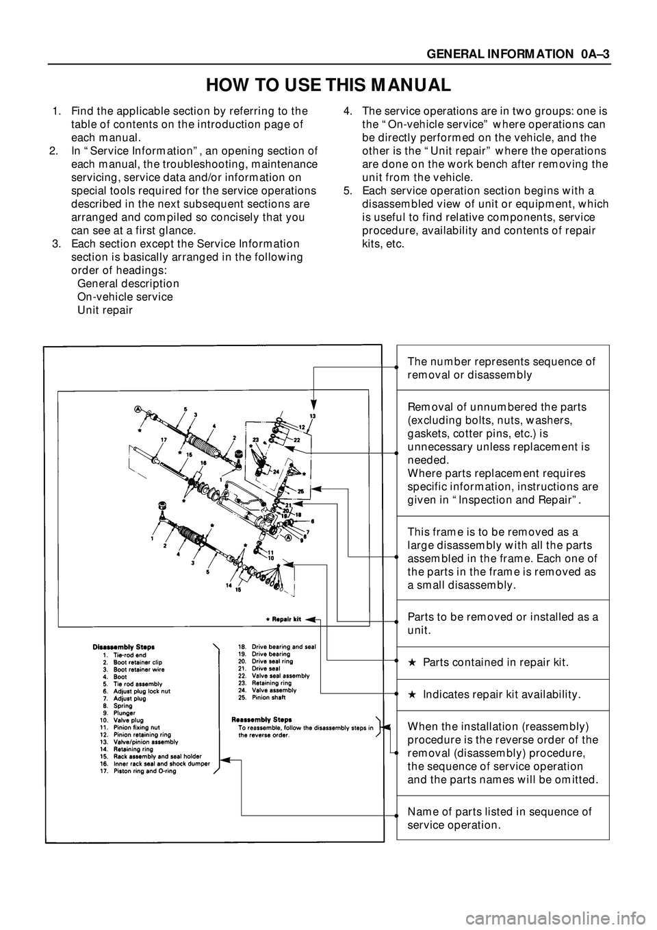
5. Each service operation section begins with a
disassembled view of unit or equipment, which
is useful to find relative components, service
procedure, availability and contents of repair
kits, etc.
The number represents sequence of
removal or disassembly
Removal of unnumbered the parts
(excluding bolts, nuts, washers,
gaskets, cotter pins, etc.) is
unnecessary unless replacement is
needed.
Where parts replacement requires
specific information, instructions are
given in ÒInspection and RepairÓ.
This frame is to be removed as a
large disassembly with all the parts
assembled in the frame. Each one of
the parts in the frame is removed as
a small disassembly.
Parts to be removed or installed as a
unit.
H Parts contained in repair kit.
H Indicates repair kit availability.
When the installation (reassembly)
procedure is the reverse order of the
removal (disassembly) procedure,
the sequence of service operation
and the parts names will be omitted.
Name of parts listed in sequence of
service operation.
Page 25 of 3573
GENERAL INFORMATION 0AÐ11
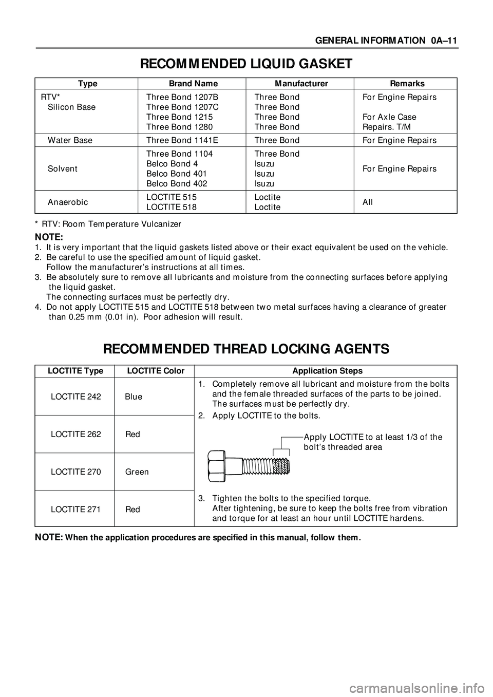
RECOMMENDED LIQUID GASKET
* RTV: Room Temperature Vulcanizer
NOTE:
1. It is very important that the liquid gaskets listed above or their exact equivalent be used on the vehicle.
2. Be careful to use the specified amount of liquid gasket.
Follow the manufacturerÕs instructions at all times.
3. Be absolutely sure to remove all lubricants and moisture from the connecting surfaces before applying
the liquid gasket.
The connecting surfaces must be perfectly dry.
4. Do not apply LOCTITE 515 and LOCTITE 518 between two metal surfaces having a clearance of greater
than 0.25 mm (0.01 in). Poor adhesion will result.
RECOMMENDED THREAD LOCKING AGENTS
NOTE:When the application procedures are specified in this manual, follow them.
Type Brand Name Manufacturer Remarks
RTV* Three Bond 1207B Three Bond For Engine Repairs
Silicon Base Three Bond 1207C Three Bond
Three Bond 1215 Three Bond For Axle Case
Three Bond 1280 Three Bond Repairs. T/M
Water Base Three Bond 1141E Three Bond For Engine Repairs
Three Bond 1104 Three Bond
Belco Bond 4 Isuzu
Solvent
Belco Bond 401 Isuzu For Engine Repairs
Belco Bond 402 Isuzu
LOCTITE 515 Loctite
Anaerobic
LOCTITE 518 Loctite All
LOCTITE Type LOCTITE Color Application Steps
LOCTITE 242 Blue
LOCTITE 262 Red
LOCTITE 270 Green
LOCTITE 271 Red
1. Completely remove all lubricant and moisture from the bolts
and the female threaded surfaces of the parts to be joined.
The surfaces must be perfectly dry.
2. Apply LOCTITE to the bolts.
Apply LOCTITE to at least 1/3 of the
boltÕs threaded area
3. Tighten the bolts to the specified torque.
After tightening, be sure to keep the bolts free from vibration
and torque for at least an hour until LOCTITE hardens.
Page 26 of 3573
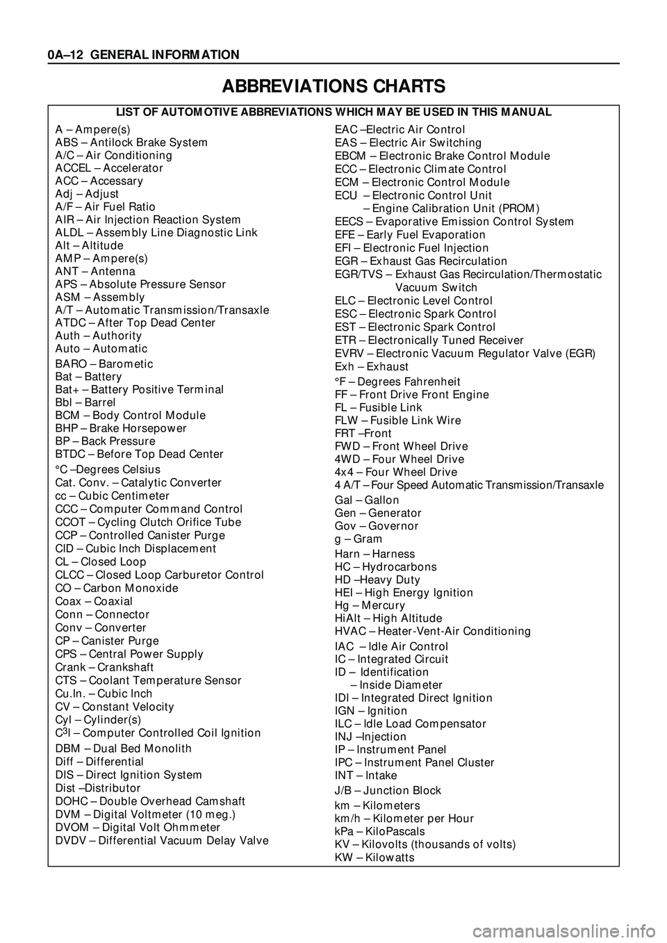
ABBREVIATIONS CHARTS
LIST OF AUTOMOTIVE ABBREVIATIONS WHICH MAY BE USED IN THIS MANUAL
A Ð Ampere(s)
ABS Ð Antilock Brake System
A/C Ð Air Conditioning
ACCEL Ð Accelerator
ACC Ð Accessary
Adj Ð Adjust
A/F Ð Air Fuel Ratio
AIR Ð Air Injection Reaction System
ALDL Ð Assembly Line Diagnostic Link
Alt Ð Altitude
AMP Ð Ampere(s)
ANT Ð Antenna
APS Ð Absolute Pressure Sensor
ASM Ð Assembly
A/T Ð Automatic Transmission/Transaxle
ATDC Ð After Top Dead Center
Auth Ð Authority
Auto Ð Automatic
BARO Ð Barometic
Bat Ð Battery
Bat+ Ð Battery Positive Terminal
Bbl Ð Barrel
BCM Ð Body Control Module
BHP Ð Brake Horsepower
BP Ð Back Pressure
BTDC Ð Before Top Dead Center
¡C ÐDegrees Celsius
Cat. Conv. Ð Catalytic Converter
cc Ð Cubic Centimeter
CCC Ð Computer Command Control
CCOT Ð Cycling Clutch Orifice Tube
CCP Ð Controlled Canister Purge
CID Ð Cubic Inch Displacement
CL Ð Closed Loop
CLCC Ð Closed Loop Carburetor Control
CO Ð Carbon Monoxide
Coax Ð Coaxial
Conn Ð Connector
Conv Ð Converter
CP Ð Canister Purge
CPS Ð Central Power Supply
Crank Ð Crankshaft
CTS Ð Coolant Temperature Sensor
Cu.In. Ð Cubic Inch
CV Ð Constant Velocity
Cyl Ð Cylinder(s)
C
3I Ð Computer Controlled Coil Ignition
DBM Ð Dual Bed Monolith
Diff Ð Differential
DIS Ð Direct Ignition System
Dist ÐDistributor
DOHC Ð Double Overhead Camshaft
DVM Ð Digital Voltmeter (10 meg.)
DVOM Ð Digital Volt Ohmmeter
DVDV Ð Differential Vacuum Delay Valve
EAC ÐElectric Air Control
EAS Ð Electric Air Switching
EBCM Ð Electronic Brake Control Module
ECC Ð Electronic Climate Control
ECM Ð Electronic Control Module
ECU Ð Electronic Control Unit
Ð Engine Calibration Unit (PROM)
EECS Ð Evaporative Emission Control System
EFE Ð Early Fuel Evaporation
EFI Ð Electronic Fuel Injection
EGR Ð Exhaust Gas Recirculation
EGR/TVS Ð Exhaust Gas Recirculation/Thermostatic
Vacuum Switch
ELC Ð Electronic Level Control
ESC Ð Electronic Spark Control
EST Ð Electronic Spark Control
ETR Ð Electronically Tuned Receiver
EVRV Ð Electronic Vacuum Regulator Valve (EGR)
Exh Ð Exhaust
¡F Ð Degrees Fahrenheit
FF Ð Front Drive Front Engine
FL Ð Fusible Link
FLW Ð Fusible Link Wire
FRT ÐFront
FWD Ð Front Wheel Drive
4WD Ð Four Wheel Drive
4x4 Ð Four Wheel Drive
4 A/T Ð Four Speed Automatic Transmission/Transaxle
Gal Ð Gallon
Gen Ð Generator
Gov Ð Governor
g Ð Gram
Harn Ð Harness
HC Ð Hydrocarbons
HD ÐHeavy Duty
HEI Ð High Energy Ignition
Hg Ð Mercury
HiAlt Ð High Altitude
HVAC Ð Heater-Vent-Air Conditioning
IAC Ð Idle Air Control
IC Ð Integrated Circuit
ID Ð Identification
Ð Inside Diameter
IDI Ð Integrated Direct Ignition
IGN Ð Ignition
ILC Ð Idle Load Compensator
INJ ÐInjection
IP Ð Instrument Panel
IPC Ð Instrument Panel Cluster
INT Ð Intake
J/B Ð Junction Block
km Ð Kilometers
km/h Ð Kilometer per Hour
kPa Ð KiloPascals
KV Ð Kilovolts (thousands of volts)
KW Ð Kilowatts
0AÐ12 GENERAL INFORMATION
Page 27 of 3573
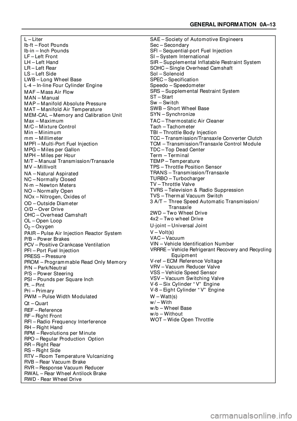
SAE Ð Society of Automotive Engineers
Sec Ð Secondary
SFI Ð Sequential-port Fuel Injection
SI Ð System International
SIR Ð Supplemental Inflatable Restraint System
SOHC Ð Single Overhead Camshaft
Sol Ð Solenoid
SPEC Ð Specification
Speedo Ð Speedometer
SRS Ð Supplemental Restraint System
ST Ð Start
Sw Ð Switch
SWB Ð Short Wheel Base
SYN Ð Synchronize
TAC Ð Thermostatic Air Cleaner
Tach Ð Tachometer
TBI Ð Throttle Body Injection
TCC Ð Transmission/Transaxle Converter Clutch
TCM Ð Transmission/Transaxle Control Module
TDC Ð Top Dead Center
Term Ð Terminal
TEMP Ð Temperature
TPS Ð Throttle Position Sensor
TRANS Ð Transmission/Transaxle
TURBO Ð Turbocharger
TV Ð Throttle Valve
TVRS Ð Television & Radio Suppression
TVS Ð Thermal Vacuum Switch
3 A/T Ð Three Speed Automatic Transmission/
Transaxle
2WD Ð Two Wheel Drive
4x2 Ð Two wheel Drive
U-joint Ð Universal Joint
V Ð Volt(s)
VAC Ð Vacuum
VIN Ð Vehicle Identification Number
VRRRE Ð Vehicle Refrigerant Recovery and Recycling
Equipment
V-ref Ð ECM Reference Voltage
VRV Ð Vacuum Reducer Valve
VSS Ð Vehicle Speed Sensor
VSV Ð Vacuum Switching Valve
V-6 Ð Six Cylinder ÒVÓ Engine
V-8 Ð Eight Cylinder ÒVÓ Engine
W Ð Watt(s)
w/ Ð With
w/b Ð Wheel Base
w/o Ð Without
WOT Ð Wide Open ThrottleL Ð Liter
lbáft Ð Foot Pounds
lbáin Ð Inch Pounds
LF Ð Left Front
LH Ð Left Hand
LR Ð Left Rear
LS Ð Left Side
LWB Ð Long Wheel Base
L-4 Ð In-line Four Cylinder Engine
MAF Ð Mass Air Flow
MAN Ð Manual
MAP Ð Manifold Absolute Pressure
MAT Ð Manifold Air Temperature
MEM-CAL Ð Memory and Calibration Unit
Max Ð Maximum
M/C Ð Mixture Control
Min Ð Minimum
mm Ð Millimeter
MPFI Ð Multi-Port Fuel Injection
MPG Ð Miles per Gallon
MPH Ð Miles per Hour
M/T Ð Manual Transmission/Transaxle
MV Ð Millivolt
NA Ð Natural Aspirated
NC Ð Normally Closed
Nám Ð Newton Meters
NO Ð Normally Open
NOx Ð Nitrogen, Oxides of
OD Ð Outside Diameter
O/D Ð Over Drive
OHC Ð Overhead Camshaft
OL Ð Open Loop
O
2Ð Oxygen
PAIR Ð Pulse Air Injection Reactor System
P/B Ð Power Brakes
PCV Ð Positive Crankcase Ventilation
PFI Ð Port Fuel Injection
PRESS Ð Pressure
PROM Ð Programmable Read Only Memory
P/N Ð Park/Neutral
P/S Ð Power Steering
PSI Ð Pounds per Square Inch
Pt. Ð Pint
Pri Ð Primary
PWM Ð Pulse Width Modulated
Qt Ð Quart
REF Ð Reference
RF Ð Right Front
RFI Ð Radio Frequency Interference
RH Ð Right Hand
RPM Ð Revolutions per Minute
RPO Ð Regular Production Option
RR Ð Right Rear
RS Ð Right Side
RTV Ð Room Temperature Vulcanizing
RVB Ð Rear Vacuum Brake
RVR Ð Response Vacuum Reducer
RWAL Ð Rear Wheel Antilock Brake
RWD - Rear Wheel Drive
GENERAL INFORMATION 0AÐ13
Page 28 of 3573

MAINTENANCE AND LUBRICATION 0BÐ1
SECTION 0B
MAINTENANCE AND LUBRICATION
CONTENTS
PAGE
Maintenance Schedule...................................................0BÐ 2
Recommended Fluids, Lubricants and Fuels.................................0BÐ 7
Oil Viscosity Chart.......................................................0BÐ10
Service Precaution
WARNING: THIS VEHICLE HAS A SUPPLEMENTAL
RESTRAINT SYSTEM (SRS). REFER TO THE SRS
COMPONENT AND WIRING LOCATION VIEW IN
ORDER TO DETERMINE WHETHER YOU ARE
PERFORMING SERVICE ON OR NEAR THE SRS
COMPONENTS OR THE SRS WIRING. WHEN YOU
ARE PERFORMING SERVICE ON OR NEAR THE
SRS COMPONENTS OR THE SRS WIRING, REFER
TO THE SRS SERVICE INFORMATION. FAILURE
TO FOLLOW WARNINGS COULD RESULT IN
POSSIBLE AIR BAG DEPLOYMENT, PERSONAL
INJURY, OR OTHERWISE UNNEEDED SRS
SYSTEM REPAIRS.CAUTION: Always use the correct fastener in the
proper location. When you replace a fastener, use
ONLY the exact part number for that application.
ISUZU will call out those fasteners that require a
replacement after removal. ISUZU will also call out
the fasteners that require thread lockers or thread
sealant. UNLESS OTHERWISE SPECIFIED, do not
use supplemental coatings (Paints, greases, or
other corrosion inhibitors) on threaded fasteners
or fasteners joint interfaces. Generally, such
coatings adversely affect the fastener torque and
the joint clamping force, and may damage the
fastener. When you install fasteners, use the
correct tightening sequence and specification.
Following these instructions can help you avoid
damage to parts and systems.