Page 626 of 3573
4B2±55 DRIVE LINE CONTROL SYSTEM (TOD)
StepActionYe sNo
11. Turn off the starter switch.
2. Disconnect the ECU connector from ECU.
Does the resistance between terminals 5 and 19 meet the
standard, R = 21 + 4 ohms?The phenomenon
is not
reproduced.
Refer to
ªTroubles
intermittently
observedº.
Go to Step 4
Go to Step 2
2Is the resistance between terminals 5 and 19 R<2 ohms?The signal line
circuit of the shift
on the fly system
is short-circuited
to GND. Repair
the circuit.
Go to Step 3
Go to Step 3
3Is the resistance between terminals 5 and 19 R= 9+7ohms?The signal line
circuit of the shift
on the fly system
is layer
short-circuited*.
Replace the valve
(VSV).
Go to Step 3
Go to Step 4
41. Check that all the parts are mounted.
2. Clear the trouble code.
Is this step complete?
Repeat the
ªDiagnosis Flowº.
Return to Step 4
*Layer short-circuit : The coil is damaged by overcurrent.
Page 659 of 3573
 4B2±88
StepActionYe sNo
1Are the front and rear tires in specified size?
Go to Step 2
Replace the tires
with specified
ones, and service
the new tires.
Go to Step 16")
DRIVE LINE CONTROL SYSTEM (TOD) 4B2±88
StepActionYe sNo
1Are the front and rear tires in specified size?
Go to Step 2
Replace the tires
with specified
ones, and service
the new tires.
Go to Step 16
2Is the tire pressure correct?
Go to Step 3
Replace the tires
with specified
ones, and service
the new tires.
Go to Step 16
3Are the tires free from abnormal wear?
Go to Step 4
Replace the tires
with specified
ones, and service
the new tires.
Go to Step 16
4Are different types of tires used?
Go to Step 5
Replace the tires
with specified
ones, and service
the new tires.
Go to Step 16
51. Start the engine.
2. Shift the transfer lever to the high (TOD) position.
3. Fully turn the steering to the left (or right) end, and select the D
range and start the creep run.
Does the tight corner braking occur? Is the judder with chug-chug
sound observed? * Use caution on the operation.
Go to Step 6 Go to Step 11
61. Shift the transfer lever to the 2H position.
2. Fully turn the steering to the left (or right) end, and select the D
range and start the creep run.
Does the tight corner braking occur? Is the judder with chug-chug
sound observed? * Use caution on the operation.
Go to Step 7 Go to Step 14
7Is an LSD mounted to the rear differential? Go to Step 8 Go to Step 9
8Is the genuine LSD oil used in the rear differential?
Go to Step 9
Replace the
differential oil.
Go to Step 16
9Does the engine output the power correctly?
Go to Step 10
Check the
engine.
Go to Step 16
10Do the speed sensors work correctly? (Check trouble codes.)The ECU has
failed. Replace
the ECU.
Go to Step 16
Replace the
speed sensors.
Go to Step 16
11Is the tight corner braking observed only when the brake is
applied?
Go to Step 12
Conduct full
steering under
WOT.
Go to Step 5
121. Turn off the starter switch.
2. Disconnect the ECU connector.
Is the battery voltage observed between terminals (B±68)6 and
(B±67)11?
Go to Step 13
Repair the circuit
of terminal 6
(ABS IN).
Go to Step 16
Page 671 of 3573
4C±5 DRIVE SHAFT SYSTEM
7. Remove the parking brake cable mounting
bolts(Behind the back plate)(1).
311RS001
8. Remove the bearing holder mounting nuts.
9. Remove axle shaft assembly.
NOTE: Be sure not to damage the oil seal.
10. Remove snap ring.
11. Using a bearing remover 5±8840±2295±0 and press,
remove retainer together with the bearing holder.
420RW024
12. Remove bearing.
13. Remove bearing holder.
14. Remove back plate.15. Remove the wheel pins using a remover
5±8840±0079±0.
420RW023
Inspection and Repair
Make necessary correction or parts replacement if wear,
corrosion or any other abnormal conditions are found
through inspection.
Visual Check:
Check the following parts for wear, damage, noise or any
other abnormal conditions:
1. Axle shaft
2. Bearing
When checking the axle shaft, pay special attention to the
splined portions and replace the shaft if distortion or step
wear is noticeable. Correct slight step wear with a grinder.
420RS008
Page 676 of 3573
.
12.")
4C±10
DRIVE SHAFT SYSTEM
8. Remove lock washer and lock screw.
9. Use wrench 5±8840±2117±0, remove hub nut.
411RW005
10. Remove hub and disc assembly.
11. Remove ABS sensor ring (If equipped).
12. Remove outer bearing.
13. Remove oil seal.
14. Remove inner bearing.
15. Remove bolt , if necessary, replace the wheel pin in
the following manner.
�Apply a scribe mark(1) to disc to hub.
�Clamp the hub and disc assembly in a vise, using
protective pads. Remove the 6 disc±to±hub
retaining bolts.
411RS003
�Place hub on a suitable work surface and remove
the studs by using a hammer.
411RS004
Inspection and Repair
Make necessary correction or parts replacement if wear,
damage, corrosion or any other abnormal conditions are
found through inspection.
Check the following parts:
�Hub
�Hub bearing oil seal
�Knuckle spindle
�Disc
�Caliper
�Shift on the fly system parts (Cap, Hub flange, Shim,
Snap ring)
�ABS sensor ring (If equipped)
For inspection and servicing of disc caliper and related
parts, refer to Brakes section.
Page 682 of 3573

4C±16
DRIVE SHAFT SYSTEM
Inspection and Repair
Make necessary correction or parts replacement if wear,
damage, corrosion or any other abnormal condition are
found through inspection.
Check the following parts.
�Hub
�Hub bearing, oil seal
�Knuckle spindle
�Disc
�Caliper
�Free wheeling hub parts (Clutch, knob, follower,
inner, ring and spring)
�ABS sensor ring (if so equipped)
For inspection and servicing of disc caliper, and relative
parts, refer to Brakes section.
Reassembly
1. Install spacer.
Apply about 1 g wheel bearing grease to both face of
spacer.
2. Install ring.
Apply about 3 g wheel bearing grease to inside face
of ring.
3. Install snap ring
Assembly with grease surplus being left unwiped up
as illustrated.
411RW013
Legend
(1) Inner Assembly
(2) Apply Grease
(3) Body
4. Install inner assembly.
Apply grease to splined portion of body.
5. Install snap ring.6. Install X±ring.
Apply wheel bearing grease to hub lock ring and fit it
in knob paying attention to mounting direction.
NOTE: After fitting, make sure that the hub lock ring is not
twisted.
7. Apply wheel bearing grease to ball and spring and fit
them in knob.
8. Install knob.
1. Apply grease to outer circumference of knob and
inner circumference of cover.
2. Align detent ball (1) to a groove cut in the cover.
411RW014
9. Install snap ring.
Turn the smoother face to knob side.
10. Align the end of retaining spring (1) with clutch spring
groove (2) and fit in the spring.
411RW015
Page 688 of 3573
4C±22
DRIVE SHAFT SYSTEM
Front Drive Shaft Joint
Front Drive Shaft Joints Replace-
ment
�Refer to Front Drive Axle Assembly Replacement in
this section, and refer to Front Hub and Disc in
Suspension section.
Front Hub Bearing Preload Check
Check the hub bearing preload at the wheel pin.
New bearing and New oil seal
Preload: 20 ± 25 N (2.0 ± 2.5 kg/4.4±5.5 lb)
New bearing and New oil seal
Preload: 12 ±18 N (1.2 ± 1.8 kg/2.6±4.0 lb)
411RS001
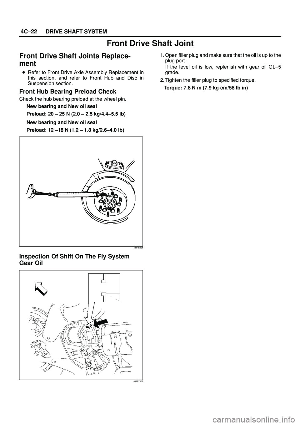
Inspection Of Shift On The Fly System
Gear Oil
412RT002
1. Open filler plug and make sure that the oil is up to the
plug port.
If the level oil is low, replenish with gear oil GL±5
grade.
2. Tighten the filler plug to specified torque.
Torque: 7.8 N´m (7.9 kg´cm/58 lb in)
Page 691 of 3573

fastening the ball retainer to the center shaft.
412RS013
9. Remove ball retainer, ball guide and bellows.
10. Raise the h")
4C±25 DRIVE SHAFT SYSTEM
8. Using snap ring pliers, remove the snap ring (1)
fastening the ball retainer to the center shaft.
412RS013
9. Remove ball retainer, ball guide and bellows.
10. Raise the hooked end of the band (1) with a
screwdriver or equivalent.
412RS014
11. Remove band.
12. Remove bellows.
13. Remove dust seal.
14. Remove BJ shaft assembly.
15. Remove the mounting bracket fixing bolts, and then
remove DOJ case assembly from the axle case.
16. Remove snap ring and bearing.
17. Remove snap ring and oil seal.
18. Remove bracket.
Inspection and Repair
Make necessary correction or parts replacement if wear,
damage, corrosion or any other abnormal conditions are
found through inspection.
Check the following parts:
1. Drive shaft joint assembly
2. DOJ case, ball, ball guide, ball retainer
3. Bellows
4. Bearing
5. Dust seal, oil seal
Bushing Replacement
�Remove the bushings using a remover
5±8840±2309±0 and hammer.
412RW051
�By using installer and base 5±8840±2309±0, press fit
the bushings into the bracket.
412RW052
Page 692 of 3573

4C±26
DRIVE SHAFT SYSTEM
Reassembly
1. Install DOJ case to bracket.
2. Install oil seal and fix snap ring.
3. Install bearing and fix snap ring.
4. Install bracket to axle case. Tighten the bracket bolt to
the specified torque.
Torque: 116 N´m (11.8 kg´m/85 lb ft)
5. Apply 150g of the specified grease in BJ .
6. Install dust seal .
7. Apply a thin coat of grease to the shaft for smooth
installation then install bellows.
8. Install band. Note the setting direction. After
installation, check that the bellows is free from
distortion.
412RS017
9. Install another bellows and fix band.
10. Install the ball guide with the smaller diameter side
ahead onto the shaft.
11. Install ball retainer.
12. Using snap ring pliers, install the snap ring (1)
securing the ball retainer to the shaft.
412RS013
13. Align the track on the ball (1) retainer with the window
in the cage, and install the six balls into position.
412RS018
14. Install spacer.
15. Install snap ring.
16. Enclose 150g of the specified grease in DOJ case,
then install drive shaft joint assembly. After
reassembly, move the DOJ longitudinally several
times to get to fit.
17. Install the circlip (1) so that open ends are positioned
away from the ball groove.

StepActionYe sNo
11. Turn off the starter switch.
2. Disconnect the ECU connector from ECU.
Does the resistance between terminals 5 and 19 meet the
standard, R")
(1).
311RS001
8. Remove the bearing holder mounting nuts.
9. Remove axle shaft assembly.
NOTE: Be sure n")