Page 85 of 3573

00 Ð 46 SERVICE INFORMATION
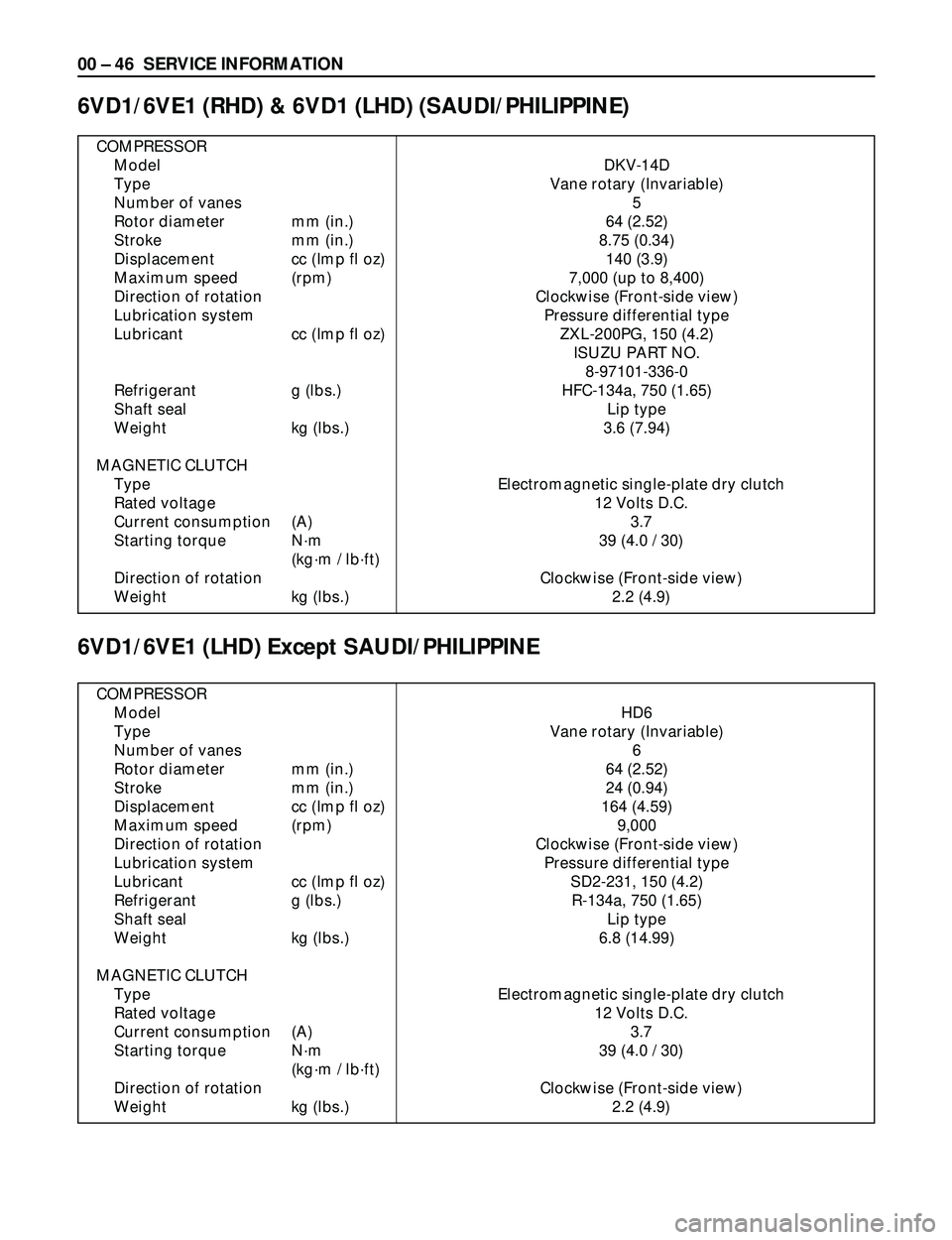
COMPRESSOR
Model DKV-14D
Type Vane rotary (Invariable)
Number of vanes 5
Rotor diameter mm (in.) 64 (2.52)
Stroke mm (in.) 8.75 (0.34)
Displacement cc (Imp fl oz) 140 (3.9)
Maximum speed (rpm) 7,000 (up to 8,400)
Direction of rotation Clockwise (Front-side view)
Lubrication system Pressure differential type
Lubricant cc (Imp fl oz) ZXL-200PG, 150 (4.2)
ISUZU PART NO.
8-97101-336-0
Refrigerant g (lbs.) HFC-134a, 750 (1.65)
Shaft seal Lip type
Weight kg (lbs.) 3.6 (7.94)
MAGNETIC CLUTCH
Type Electromagnetic single-plate dry clutch
Rated voltage 12 Volts D.C.
Current consumption (A) 3.7
Starting torque Nám 39 (4.0 / 30)
(kgám / lbáft)
Direction of rotation Clockwise (Front-side view)
Weight kg (lbs.) 2.2 (4.9)
6VD1/6VE1 (RHD) & 6VD1 (LHD) (SAUDI/PHILIPPINE)
6VD1/6VE1 (LHD) Except SAUDI/PHILIPPINE
COMPRESSOR
Model HD6
Type Vane rotary (Invariable)
Number of vanes 6
Rotor diameter mm (in.) 64 (2.52)
Stroke mm (in.) 24 (0.94)
Displacement cc (Imp fl oz) 164 (4.59)
Maximum speed (rpm) 9,000
Direction of rotation Clockwise (Front-side view)
Lubrication system Pressure differential type
Lubricant cc (Imp fl oz) SD2-231, 150 (4.2)
Refrigerant g (lbs.) R-134a, 750 (1.65)
Shaft seal Lip type
Weight kg (lbs.) 6.8 (14.99)
MAGNETIC CLUTCH
Type Electromagnetic single-plate dry clutch
Rated voltage 12 Volts D.C.
Current consumption (A) 3.7
Starting torque Nám 39 (4.0 / 30)
(kgám / lbáft)
Direction of rotation Clockwise (Front-side view)
Weight kg (lbs.) 2.2 (4.9)
Page 86 of 3573
SERVICE INFORMATION 00 Ð 47
4JG2/4JX1
COMPRESSOR
Model DKS-15CH
Type Swash plate type
Number of cylinder 6
Bore mm (in.) 36 (1.4)
Stroke mm (in.) 24 (0.94)
Displacement cc (Imp fl oz) 147 (4.1)
Maximum speed (rpm) 7,000 (up to 8,400)
Direction of rotation Clockwise (Front-side view)
Lubrication system Pressure differential type
Lubricant cc (Imp fl oz) ZXL-100PG, 150 (4.2)
ISUZU PART NO.
8-97101-338-0
Refrigerant g (lbs.) HFC-134a, 750 (1.65)
Shaft seal Lip type
Weight kg (lbs.) 4.1 (9.0)
MAGNETIC CLUTCH
Type Electromagnetic single-plate dry clutch
Rated voltage 12 Volts D.C.
Current consumption (A) 3.7
Starting torque Nám 49 (5.0 / 36)
(kgám / lbáft)
Direction of rotation Clockwise (Front-side view)
Weight kg (lbs.) 2.3 (5.1)
Page 89 of 3573
00 Ð 50 SERVICE INFORMATION
Legend
1. Clutch Driver
2. Rotor Bearing Retainer
3. Pulley Rotor and Bearing
Assembly
4. Clutch Coil Assembly
5. Connector
6. Shaft Seal Parts
7. Pump Assembly
8. High Pressure Relief Valve
9. Shipping Cap
10. Special 134a Suction Port
11. Special 134a Discharge Port
Caution
The operations described below are based
on bench overhaul with the compressor
removed from the vehicle, except as noted.
They have been prepared in order of
accessibility of the components. When a
compressor is removed from the vehicle for
servicing, the amount of PAG lubricant
remaining in the compressor should be
drained, measured and recorded. This PAG
lubricant should then be discarded and an
equal amount of new PAG lubricant added to
the compressor.
The service compressor is shipped without
PAG oil. When service procedures require,
use only Isuzu approved PAG oil.
HEATING, VENTILATION AND AIR CONDITIONING(HVAC)
1
2
3
4
5
68
97
10
11
871RW002
Page 90 of 3573
SERVICE INFORMATION 00 Ð 51
Metric Thread Size Information
Compressor to mounting bracket bolts(Front)
M10´1.5 Ð 6H
Compressor to mounting bracket bolts(Rear)
M8´1.25 Ð 6H
Suction-discharge port screw
M10´1.5 Ð 6H
Compressor shaft
M9´1.25 Ð 6H
Internal hub-clutch drive assembly
M22´1.5 Ð 6H
Page 94 of 3573
SERVICE INFORMATION 00 Ð 55
ILLUSTRATION TOOL NO. TOOL NAME
5-8840-2610-0
Hub and Clutch Drive Plate Asm. remover
(J-33013-B)
5-8840-2615-0
Compressor Holding Fixture
(J-33026)
5-8840-2612-0
Puller Pilot
(J-33023-A)
5-8840-2617-0
Pulley Puller
(J-41552)
5-8840-2611-0
Pulley and Bearing Assembly Installer
(J-33017)
5-8840-0111-0
Puller Bar
(J-8433-1)
5-8840-0111-0
Forcing Screw
(J-8433-3)
5-8840-2614-0
Clutch Coil Installer Adapter
(J-33025)
5-8840-2613-0
Clutch Coil Installer Adapter
(J-33024)
5-8840-2629-0
Seal Seat Remover and Installer
(J-23128-A)
5-8840-2630-0
O-Ring Remover
(J-9553-01)
DELPHI Harrison HD6/HDT6 Special Tools
901RW012
901RW013
901RW015
901RW016
901RW017
901RW018
901RW019
901RW020
901RW021
901RW024
901RW025
Page 127 of 3573

AIR CONDITIONING 1B Ð 1
CAUTION
When fasteners are removed, always
reinstall them at the same location from
which they were removed. If a fastener
needs to be replaced, use the correct part
number fastener for that application. If the
correct part number fastener is not available,
a fastener of equal size and strength (or
stronger) may be used. Fasteners that are not reused, and those
requiring thread locking compound, will be
called out. The correct torque values must
be used when installing fasteners that
require it. If the above conditions are not
followed, parts or system damage could
result.
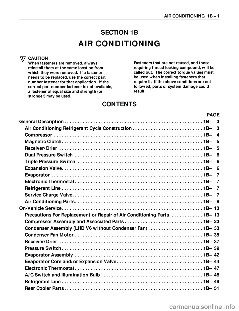
SECTION 1B
AIR CONDITIONING
CONTENTS
PAGE
General Description.....................................................1BÐ 3
Air Conditioning Refrigerant Cycle Construction...........................1BÐ 3
Compressor.........................................................1BÐ 4
Magnetic Clutch......................................................1BÐ 5
Receiver/Drier.......................................................1BÐ 5
Dual Pressure Switch.................................................1BÐ 6
Triple Pressure Switch................................................1BÐ 6
Expansion Valve......................................................1BÐ 6
Evaporator..........................................................1BÐ 7
Electronic Thermostat.................................................1BÐ 7
Refrigerant Line......................................................1BÐ 7
Service Charge Valve..................................................1BÐ 7
Air Conditioning Parts.................................................1BÐ 8
On-Vehicle Service......................................................1BÐ 13
Precautions For Replacement or Repair of Air Conditioning Parts.............1BÐ 13
Compressor Assembly and Associated Parts..............................1BÐ 23
Condenser Assembly (LHD V6 without Condenser Fan).....................1BÐ 33
Condenser Fan Motor.................................................1BÐ 35
Receiver/Drier.......................................................1BÐ 37
Pressure Switch......................................................1BÐ 39
Evaporator Assembly.................................................1BÐ 42
Evaporator Core and/or Expansion Valve.................................1BÐ 44
Electronic Thermostat.................................................1BÐ 47
A/C Switch and Illumination Bulb.......................................1BÐ 48
Refrigerant Line......................................................1BÐ 49
Rear Cooler Parts.....................................................1BÐ 51
Page 128 of 3573

1B Ð 2 AIR CONDITIONING
Full Automatic Air Conditioning System....................................1BÐ 60
General Description.....................................................1BÐ 60
Full Automatic Air Conditioner Part Configuration.........................1BÐ 60
Circuit Diagram......................................................1BÐ 62
Function and Features.................................................1BÐ 74
Full Automatic Air Conditioner Block Diagram.............................1BÐ 75
Air Conditioning Parts.................................................1BÐ 76
Control Panel Layout..................................................1BÐ 80
Air Control Functions.................................................1BÐ 81
Operation and Function of Control Panel Switches.........................1BÐ 82
Overview of Construction, Movement and Control of Major Parts of Full Automatic
Air Conditioner System................................................1BÐ 84
Overview of Automatic Control of Full Automatic Air Conditioner............1BÐ 88
Troubleshooting........................................................1BÐ 92
Troubleshooting, Its Overview and Procedures............................1BÐ 92
Performance and Movement Checklist for Automatic Air Conditioner Related
Parts...............................................................1BÐ 95
Troubleshooting with Self-Diagnosis Function............................1BÐ 97
Inspection by Failed Location.............................................1BÐ100
Inspection of the Sensors..............................................1BÐ100
Inspection of the Intake Actuator System.................................1BÐ104
Inspection of the Mix Actuator System...................................1BÐ107
Inspection of the Mode Actuator System.................................1BÐ110
Inspection of the Fan Motor System.....................................1BÐ113
Inspection of the Magnet Clutch System.................................1BÐ118
Inspection of the Air Conditioner Room Temperature Setup System..........1BÐ123
Individual Inspection..................................................1BÐ124
On-Vehicle Service......................................................1BÐ126
Power Transistor.....................................................1BÐ126
Automatic Air Conditioner Control Unit..................................1BÐ126
In Car Sensor........................................................1BÐ127
Ambient Sensor......................................................1BÐ127
Sun Sensor..........................................................1BÐ128
Electronic Thermostat.................................................1BÐ128
Mode Actuator.......................................................1BÐ129
Mix Actuator.........................................................1BÐ129
Intake Actuator......................................................1BÐ130
Page 129 of 3573

AIR CONDITIONING 1B Ð 3
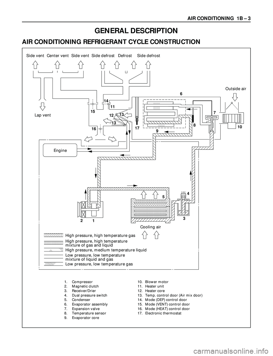
AIR CONDITIONING REFRIGERANT CYCLE CONSTRUCTION
�
��
� �
���
� ��
��
�
� ���
��
�� ������
� ���
��
�� ������
�� ����
�� ����
� ���
��
��� ����
� ���
����
�
� ���
�
����
��������� ��������� ����������������� �
������� ��������
� ��
�
� ��
�
� ��
�
�� ��
� ��
�� ��
�� ��
�� �
�� ��
��� �������� ������ �
��
� � ��
1514
11
12
13
1610
177
34
5
2
18
96
13 Side vent
Lap ventOutside air
EngineSide vent
Cooling air
High pressure, high temperature gas
High pressure, high temperature
mixture of gas and liquid
Low pressure, low temperature
mixture of liquid and gas
Low pressure, low temperature gas High pressure, medium temperature liquidSide defrost Side defrostDefrost Center vent
GENERAL DESCRIPTION
1. Compressor
2. Magnetic clutch
3. Receiver/Drier
4. Dual pressure switch
5. Condenser
6. Evaporator assembly
7. Expansion valve
8. Temperature sensor
9. Evaporator core10. Blower motor
11. Heater unit
12. Heater core
13. Temp. control door (Air mix door)
14. Mode (DEF) control door
15. Mode (VENT) control door
16. Mode (HEAT) control door
17. Electronic thermostat