Page 2183 of 3573

7A±29 AUTOMATIC TRANSMISSION (4L30±E)
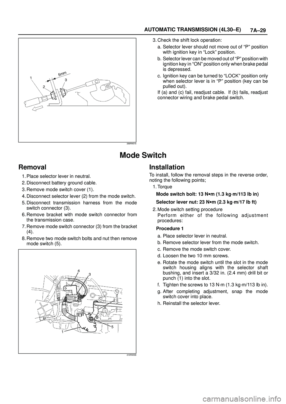
256RW015
3. Check the shift lock operation:
a. Selector lever should not move out of ªPº position
with ignition key in ªLockº position.
b. Selector lever can be moved out of ªPº position with
ignition key in ªONº position only when brake pedal
is depressed.
c. Ignition key can be turned to ªLOCKº position only
when selector lever is in ªPº position (key can be
pulled out).
If (a) and (c) fail, readjust cable. If (b) fails, readjust
connector wiring and brake pedal switch.
Mode Switch
Removal
1. Place selector lever in neutral.
2. Disconnect battery ground cable.
3. Remove mode switch cover (1).
4. Disconnect selector lever (2) from the mode switch.
5. Disconnect transmission harness from the mode
switch connector (3).
6. Remove bracket with mode switch connector from
the transmission case.
7. Remove mode switch connector (3) from the bracket
(4).
8. Remove two mode switch bolts and nut then remove
mode switch (5).
210RW008
Installation
To install, follow the removal steps in the reverse order,
noting the following points;
1. Torque
Mode switch bolt: 13 Nwm (1.3 kg´m/113 lb in)
Selector lever nut: 23 Nwm (2.3 kg´m/17 lb ft)
2. Mode switch setting procedure
Perform either of the following adjustment
procedures:
Procedure 1
a. Place selector lever in neutral.
b. Remove selector lever from the mode switch.
c. Remove the mode switch cover.
d. Loosen the two 10 mm screws.
e. Rotate the mode switch until the slot in the mode
switch housing aligns with the selector shaft
bushing, and insert a 3/32 in. (2.4 mm) drill bit or
punch (1) into the slot.
f. Tighten the screws to 13 N´m (1.3 kg´m/113 lb in).
g. After completing adjustment, snap the mode
switch cover into place.
h. Reinstall the selector lever.
Page 2564 of 3573
LIGHTING SYSTEM8A–25
Seat Heater Switch
Removal
1. Disconnect the battery ground cable.
2. Remove four fixing screws and disconnect the switch
connectors to remove the front console assembly(4).
3. Push the lock from the back side of the front console
assembly to remove the seat heater switch(5).
825RW025
Installation
To install, follow the removal steps in the reverse order,
noting the following point.
1. Push the switch with your fingers until it locks
securely.
Key Remind Switch (Starter Switch)
Removal and Installation
Refer to the removal and installation on steps of the
Starter Switch in this section.
Page 2647 of 3573
8DÐ54 WIRING SYSTEM
Circuit Diagram (6V
*1) Ð 1
3
P-2H-142
2B-11
P-10
P-7
PCM
(A4)
CONDENSER
FANEHCU STARTER
(B)
STARTER
RELAY
(3)
P-6BODY ENGINE FRAMEBATTERY
STARTER
SWRELAY & FUSE BOX
CONDENSER
FAN
RELAY
FL-2 50A
KEY SWFL-3 30A
PCMFL-4 30A
CONDENSER
FANFL-6 40A
ABS FL-1 80A
MAIN 8.0
B/R
8.0
B30.0
B8.0
B30.0
B/R
3.0
W/B
3.0
W/B
3.0
W/B
3.0
B/Y3.0
W/G3.0
B/R3.0
L/B2.0
W1.25
L/O
1.25
L3.0
W/G
3.0
W/B5.0
W
5.0
W
3.0
W/B
B-11IG1 ST IG2 ACC B1
7
EF
A
B-11
3B
B-11
5C
B-11
1DB2
OFF 4
B-11
P-5P-1�´��
�µ��
X-191X-19
�ü�Z��
�&����������������������������
������������������
C�« ���
!�«
j�ø��
C�«�Ô��
�1�l�ò�8��
��������
�^�j�ø��
D08RWC56.
Page 2652 of 3573
WIRING SYSTEM 8DÐ59
Circuit Diagram (4JX1) Ð 1
P-2H-142
2B-11
P-10
P-7
STARTER
RELAY
(4)
P-6BODY ENGINE FRAMEBATTERY
STARTER
SWFUSE & RELAY BOX
FL-2 50A
KEY SW FL-1 80A
MAIN 8.0
B/R
8.0
B30.0
B8.0
B
3.0
W/B
3.0
W/B
3.0
W/B
3.0
B/Y3.0
W/G3.0
B/R3.0
L/B 3.0
W/B 3.0
W/B 30.0
B/R
B-11IG1 ST IG2 ACC B1
7
EFG
A
B-11
3B
B-11
5C
B-11
1DB2
OFF 4
B-11
STARTER
(B)
P-5P-1�´
�µ
X-112
4X-11ECM
(J3-1)
ECM
RELAY-1
FL-4 50A
ECM
3.0
R 3.0
W/B
X-102
4X-10ECM
(J3-2)
ECM
�3�&�-�"�:����
3.0
R/W3.0
W/B
D08RWB17
Page 2653 of 3573
8DÐ60 WIRING SYSTEM
Circuit Diagram (4JG2) Ð 1
P-2H-142
2B-11
P-10
P-7
STARTER
RELAY
(4)
P-6BODY ENGINE FRAMEBATTERY
STARTER
SWFUSE & RELAY BOX
FL-2 50A
KEY SW FL-1 80A
MAIN 8.0
B/R
8.0
B30.0
B8.0
B
3.0
W/B
3.0
W/B
3.0
W/B
3.0
B/Y3.0
W/G3.0
B/R3.0
L/B 3.0
W/B 3.0
W/B 30.0
B/R
B-11IG1 ST IG2 ACC B1
7
EFG
A
B-11
3B
B-11
5C
B-11
1DB2
OFF 4
B-11
STARTER
(B)
P-5P-1�´��
�µ��
X-191
3X-19
CONDENSER
FAN
CONDENSER
FAN
RELAY
FL-4 30A
CONDENSER
FAN
1.25
L 1.25
L/O
D08RWC54
Page 2837 of 3573
8DÐ244 WIRING SYSTEM
Power Door Lock
General Description
The circuit consists of door lock (& power window)
switch, door lock actuator for front and rear door,
tailgate lock actuator and door lock key switch.
Front door lock switchÐLH is always provided with
battery voltage. The key or the inside lock button on
the both driverÕs and front passengerÕs door can
activate the lock mechanism of all the door
(including tailgate).
When driverÕs door lock switch or front passengerÕs
door lock switch is turned on, current flows for
about one second to door lock actuator of each door
connected in parallel with front door lock (& power
window) switchÐLH to activate actuator to lock and
unlock doors.
Page 2992 of 3573

WIRING SYSTEM 8DÐ399
Diagnosis
Diagnosis Procedure
1. Check to see if the battery voltage is normal.
2. Check to see if the fuse is normal.
3. Replace the antiÐtheft & keyless entry control unit with one reserved for test. If a trouble recurs even after replacing
the control unit, find out the cause of the trouble by referring to ÒSystem check procedureÓ and the following list.
ITEM MALFUNCTION POSSIBLE CAUSE DETECTING METHOD REMARKS
ANTIÐTHEFT
indicator light
does not flash
ANTIÐTHEFT
indicator light
does not turn off.
(Steadily on)
When door is
opened by pulling
up locking knob,
alarm does not
operate
Alarm does not
stop. Indicator light
does not change
to fully ON
condition, or does
not come on at
all.Burnt out indicator
light bulb possible.
Refer to ÒConnector
check tableÓ in this
system.
Refer to ÒConnector
check tableÓ in this
system.
Refer to ÒConnector
check tableÓ in this
system.
Refer to ÒConnector
check tableÓ in this
system.
Refer to ÒConnector
check tableÓ in this
system.
Refer to ÒConnector
check tableÓ in this
system. Defective contact of door switch,
or open circuit in door switch
wiring.
Short circuit in the detect switch.
Engine hood, doors and tailgate
are not fully closed and locked.
Defective door switch, or short
circuit in switch wiring.
Defective tamper switch, or short
circuit in wiring.
Defective lock switch, or short
circuit in wiring.
Defective engine hood switch, or
short circuit in wiring.
Defective tailgate switch, or short
circuit in wiring.
Defective control unit.
Poor contact of lock switch, or
open circuit in wiring.
Broken wire in wiring to headlight
and horn, or a blown fuse.
Defective contact of detect
switch, or damaged switch wiring.With door open, dome light and
courtesy light do not come on.
Check the control unit connector.
Check to see if doors are closed
and locked.
Dome light and courtesy light
remain lit on after closing doors.
Check the control unit connector.
Check the control unit connector.
Check the control unit connector.
Luggage room light remains lit
after closing tailgate.
Check alarm operation (See No.
46 of ÒSystem check procedureÓ),
possible cause is a poor contact
of lock switch of an open circuit in
wiring.
Check to see if headlights go out.
Check the control unit connector.
Check the control unit connector. A
C
D
E B
Page 2998 of 3573

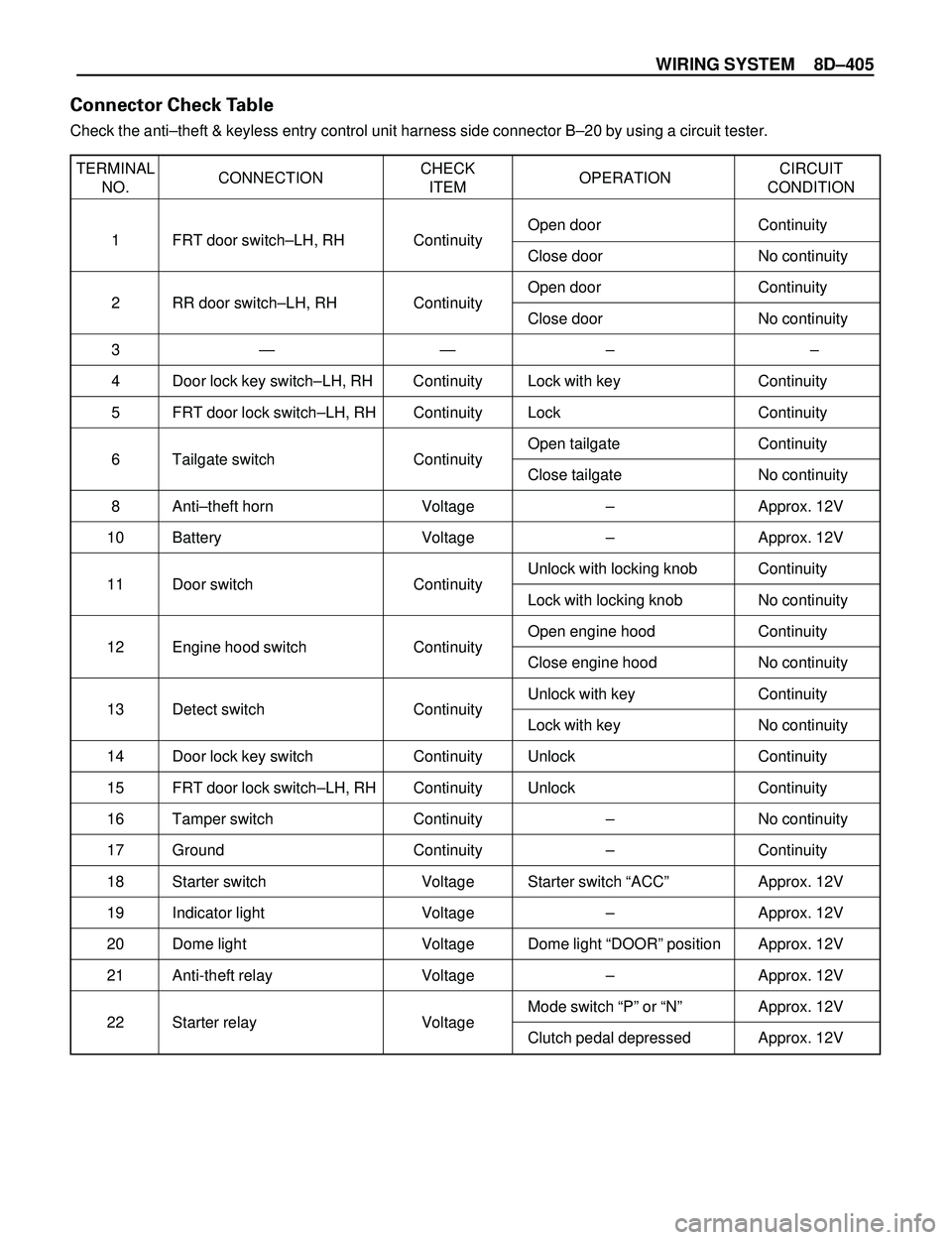
WIRING SYSTEM 8DÐ405
TERMINAL
CONNECTIONCHECK
OPERATIONCIRCUIT
NO. ITEM CONDITION
1 FRT door switchÐLH, RH ContinuityOpen door Continuity
Close door No continuity
2 RR door switchÐLH, RH ContinuityOpen door Continuity
Close door No continuity
3Ñ Ñ Ð Ð
4 Door lock key switchÐLH, RH Continuity Lock with key Continuity
5 FRT door lock switchÐLH, RH Continuity Lock Continuity
6 Tailgate switch ContinuityOpen tailgate Continuity
Close tailgate No continuity
8 AntiÐtheft horn Voltage Ð Approx. 12V
10 Battery Voltage Ð Approx. 12V
11 Door switch ContinuityUnlock with locking knob Continuity
Lock with locking knob No continuity
12 Engine hood switch ContinuityOpen engine hood Continuity
Close engine hood No continuity
13 Detect switch ContinuityUnlock with key Continuity
Lock with key No continuity
14 Door lock key switch Continuity Unlock Continuity
15 FRT door lock switchÐLH, RH Continuity Unlock Continuity
16 Tamper switch Continuity Ð No continuity
17 Ground Continuity Ð Continuity
18 Starter switch Voltage Starter switch ÒACCÓ Approx. 12V
19 Indicator light Voltage Ð Approx. 12V
20 Dome light Voltage Dome light ÒDOORÓ position Approx. 12V
21 Anti-theft relay Voltage Ð Approx. 12V
22 Starter relay VoltageMode switch ÒPÓ or ÒNÓ Approx. 12V
Clutch pedal depressed Approx. 12V
Connector Check Table
Check the antiÐtheft & keyless entry control unit harness side connector BÐ20 by using a circuit tester.