Page 2600 of 3573
WIRING SYSTEM 8DÐ7
Parts Handling
Be careful when handling electrical parts. They should not
be dropped or thrown, because short circuit or other
damage may result.
Cable Harness
1. When installing the parts, be careful not to pinch or
wedge the wiring harness.
2. All electrical connections must be kept clean and tight.3. Use a grommet or guard tube (1) to protect the wiring
harness from contacting a sharp edge or surface (2).
4. Position the wiring harness with enough clearance
from the other parts and guard the wiring harness with
a vinyl tube (2) and clips (1) to avoid direct contact.
12
2
1
Page 2605 of 3573
8DÐ12 WIRING SYSTEM
Parts for Electrical Circuit
Wiring Ð Wire color
All wires have colorÐcoded insulation.
Wires belonging to a systemÕs main harness will have a
single color (1). Wires belonging to a systemÕs subcircuits
will have a colored stripe (2). Striped wires use the
following code to show wire size and colors.
Example: 0.5 G / R
Red (Stripe color)
Green (Base color)
Wire size (0.5 mm
2)
Wiring Ð Wire Color Coding
Abbreviations are used to indicate wire color within a circuit diagram.
Refer to the following table.
Color Coding Meaning Color Coding Meaning
B Black BR Brown
W White LG Light green
R Red GR Grey
G Green P Pink
Y Yellow LB Light blue
L Blue V Violet
O Orange
1
2
Page 2607 of 3573
8DÐ14 WIRING SYSTEM
Fuse
Fuses are the most common form of circuit protection
used in vehicle wiring. A fuse is a thin piece of wire or strip
of metal encased in a glass or plastic housing. It is wired
in series with the circuit it protects. When there is an
overload of current in a circuit, such as a short of a ground,
the metal strip is designed to burn out and interrupt the
flow of current. This prevents a surge of high current from
reaching and damaging other components in the circuit.
Determine the cause of the overloaded before replacing
the fuse.
The replacement fuse must have the same amperage
specification as the original fuse.
Never replace a blown fuse with a fuse of a different
amperage specification.
Doing so can result in an electrical fire or other serious
circuit damage. A blown fuse is easily identified as shown
in the figure.
Page 2608 of 3573
WIRING SYSTEM 8DÐ15
Fusible Link
The fusible link is primarily used to protect circuits where
high amounts of current flow and where it would not be
practical to use a fuse. For example, the starter circuit.
When a current overload occurs, the fusible link melts
open and interrupts the flow of current so as to prevent
the rest of the wiring harness from burning.
Determine the cause of the overload before replacing the
fusible link. the replacement fusible link must have the
same amperage specification as the original fusible link.
Never replace a blown fusible link with fusible link of a
different amperage specification. Doing so can result in
an electrical fire or other serious circuit damage.
A blown fusible link is easily identified as shown in the
figure.
Normal Blown
Fusible Link Specifications
Type Rating Case Color Maximum Circuit Current (A)
Connector 30A Pink 15
Connector 40A Green 20
Bolted 50A Red 25
Bolted 60A Yellow 30
Bolted 80A Black 40
Page 2673 of 3573

8DÐ80 WIRING SYSTEM
Powertrain Control Module (PCM)
General Description
The Powertrain Control Module (PCM) is located in
the passenger compartment.
The PCM constantly monitors the information from
various sensors, and controls the systems that affect
vehicle performance.
The PCM performs the diagnostic function of the
system. It can recognize operational problems, alert
the driver through the Malfunction Indicator Light
(MIL) and store a Diagnostic Trouble Code (DTC) or
DTC(s) which identify the problem areas to aid the
technician in making repairs.
The PCM is designed to process the various input
informations and then sends the necessary
electrical responses to control fuel delivery, spark
timing and other emission control systems. The
input information has an interrelation to more than
one output, therefore, if the one input failed, it could
affect more than one system operation.
Refer to Driveability and Emission in Engine section
and Automatic Transmission in Transmission
section.
Page 3136 of 3573

WIRING SYSTEM 8D – 543
Supplemental Restraint System (SRS) – Air Bag
General Description
The circuit consists of Sensing and Diagnostic Mod-
ule (SDM), driver’s air bag assembly, SRS coil assem-
bly, passenger’s air bag assembly, and “AIR BAG”
warning light. SDM, SRS coil assembly (driver side
only), driver air bag assembly, passenger air bag
assembly and connector wire make up the deploy-
ment loops. The function of the deployment loops is
to supply current through air bag assembly, which
will cause deployment of the air bags in the event of
a frontal crash of sufficient force, up to 30 degrees off
the center line of the vehicle. The air bag assemblies
are only supplied enough current to deploy when the
SDM detects vehicle velocity changes severe enough
to warrant deployment.
The SDM contains a sensing device which converts
vehicle velocity changes to an electrical signal.
The electrical signal generated is processed by the
SDM and then compared to a value stored in memory.
When the generated signal exceeds the stored value,
the SDM will cause current to flow through the air bag
assembly deploying the air bags.
Refer to Supplemental Restraint System in Restraints
section.
Page 3440 of 3573

SUPPLEMENTAL RESTRAINT SYSTEM9J±3
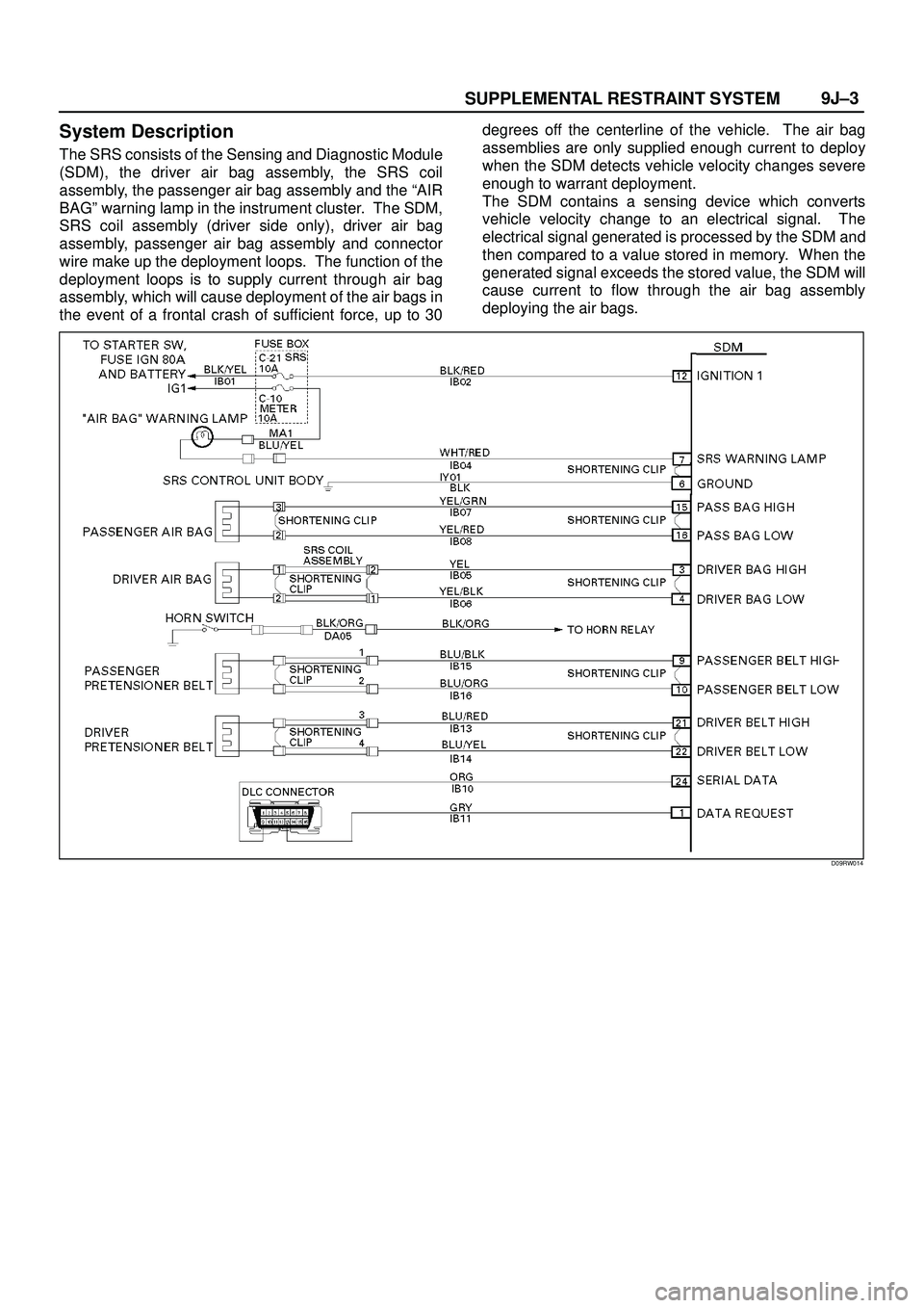
System Description
The SRS consists of the Sensing and Diagnostic Module
(SDM), the driver air bag assembly, the SRS coil
assembly, the passenger air bag assembly and the ªAIR
BAGº warning lamp in the instrument cluster. The SDM,
SRS coil assembly (driver side only), driver air bag
assembly, passenger air bag assembly and connector
wire make up the deployment loops. The function of the
deployment loops is to supply current through air bag
assembly, which will cause deployment of the air bags in
the event of a frontal crash of sufficient force, up to 30degrees off the centerline of the vehicle. The air bag
assemblies are only supplied enough current to deploy
when the SDM detects vehicle velocity changes severe
enough to warrant deployment.
The SDM contains a sensing device which converts
vehicle velocity change to an electrical signal. The
electrical signal generated is processed by the SDM and
then compared to a value stored in memory. When the
generated signal exceeds the stored value, the SDM will
cause current to flow through the air bag assembly
deploying the air bags.
D09RW014
Page 3442 of 3573

SUPPLEMENTAL RESTRAINT SYSTEM9J±5
1. Energy Reserve Ð The SDM maintains 24±Volt Loop
Reserve (24VLR) energy supply to provide
deployment energy when ignition voltage is lost in a
frontal crash.
2. Frontal Crash Detection Ð The SDM monitors
vehicle velocity changes to detect frontal crashes
which are severe enough to warrant deployment.
3. Air Bag Deployment Ð When a frontal crash of
sufficient force is detected, the SDM will cause
enough current to flow through the air bag assembly
to deploy the air bag.
4. Malfunction Detection Ð The SDM performs
diagnostic monitoring of SRS electrical components
and sets a diagnostic trouble code when a
malfunction is detected.
5. Frontal Crash Recording Ð The SDM records
information regarding SRS status during frontal
crash.
6. Malfunction Diagnosis Ð The SDM displays SRS
diagnostic trouble codes and system status
information through the use of a scan tool.
7. Driver Notification Ð The SDM warns the vehicle
driver of SRS malfunctions by controlling the ªAir
Bagº warning lamp.
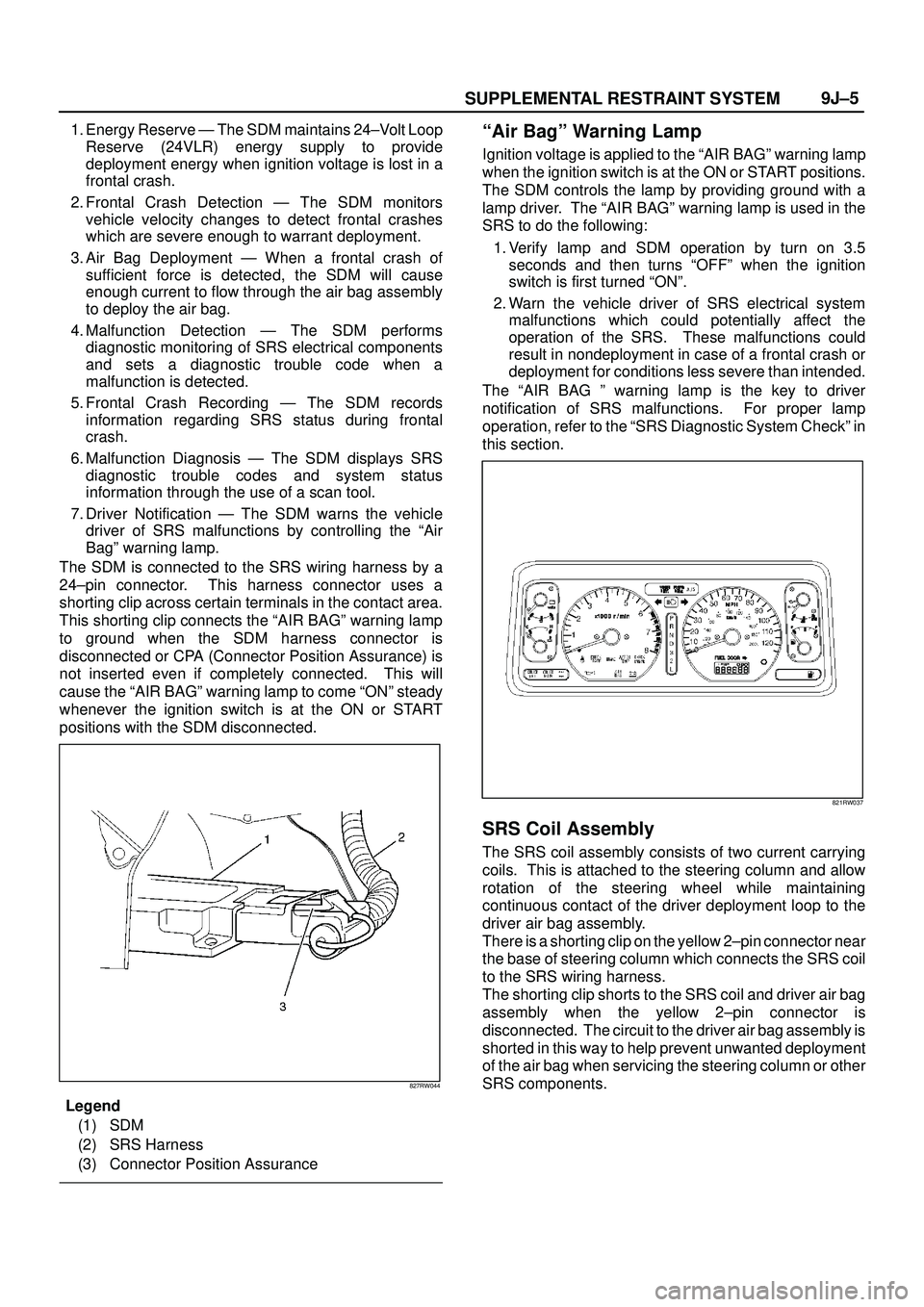
The SDM is connected to the SRS wiring harness by a
24±pin connector. This harness connector uses a
shorting clip across certain terminals in the contact area.
This shorting clip connects the ªAIR BAGº warning lamp
to ground when the SDM harness connector is
disconnected or CPA (Connector Position Assurance) is
not inserted even if completely connected. This will
cause the ªAIR BAGº warning lamp to come ªONº steady
whenever the ignition switch is at the ON or START
positions with the SDM disconnected.
827RW044
Legend
(1) SDM
(2) SRS Harness
(3) Connector Position Assurance
ªAir Bagº Warning Lamp
Ignition voltage is applied to the ªAIR BAGº warning lamp
when the ignition switch is at the ON or START positions.
The SDM controls the lamp by providing ground with a
lamp driver. The ªAIR BAGº warning lamp is used in the
SRS to do the following:
1. Verify lamp and SDM operation by turn on 3.5
seconds and then turns ªOFFº when the ignition
switch is first turned ªONº.
2. Warn the vehicle driver of SRS electrical system
malfunctions which could potentially affect the
operation of the SRS. These malfunctions could
result in nondeployment in case of a frontal crash or
deployment for conditions less severe than intended.
The ªAIR BAG º warning lamp is the key to driver
notification of SRS malfunctions. For proper lamp
operation, refer to the ªSRS Diagnostic System Checkº in
this section.
821RW037
SRS Coil Assembly
The SRS coil assembly consists of two current carrying
coils. This is attached to the steering column and allow
rotation of the steering wheel while maintaining
continuous contact of the driver deployment loop to the
driver air bag assembly.
There is a shorting clip on the yellow 2±pin connector near
the base of steering column which connects the SRS coil
to the SRS wiring harness.
The shorting clip shorts to the SRS coil and driver air bag
assembly when the yellow 2±pin connector is
disconnected. The circuit to the driver air bag assembly is
shorted in this way to help prevent unwanted deployment
of the air bag when servicing the steering column or other
SRS components.