Page 581 of 3573
DRIVE LINE CONTROL SYSTEM (TOD) 4B2±10
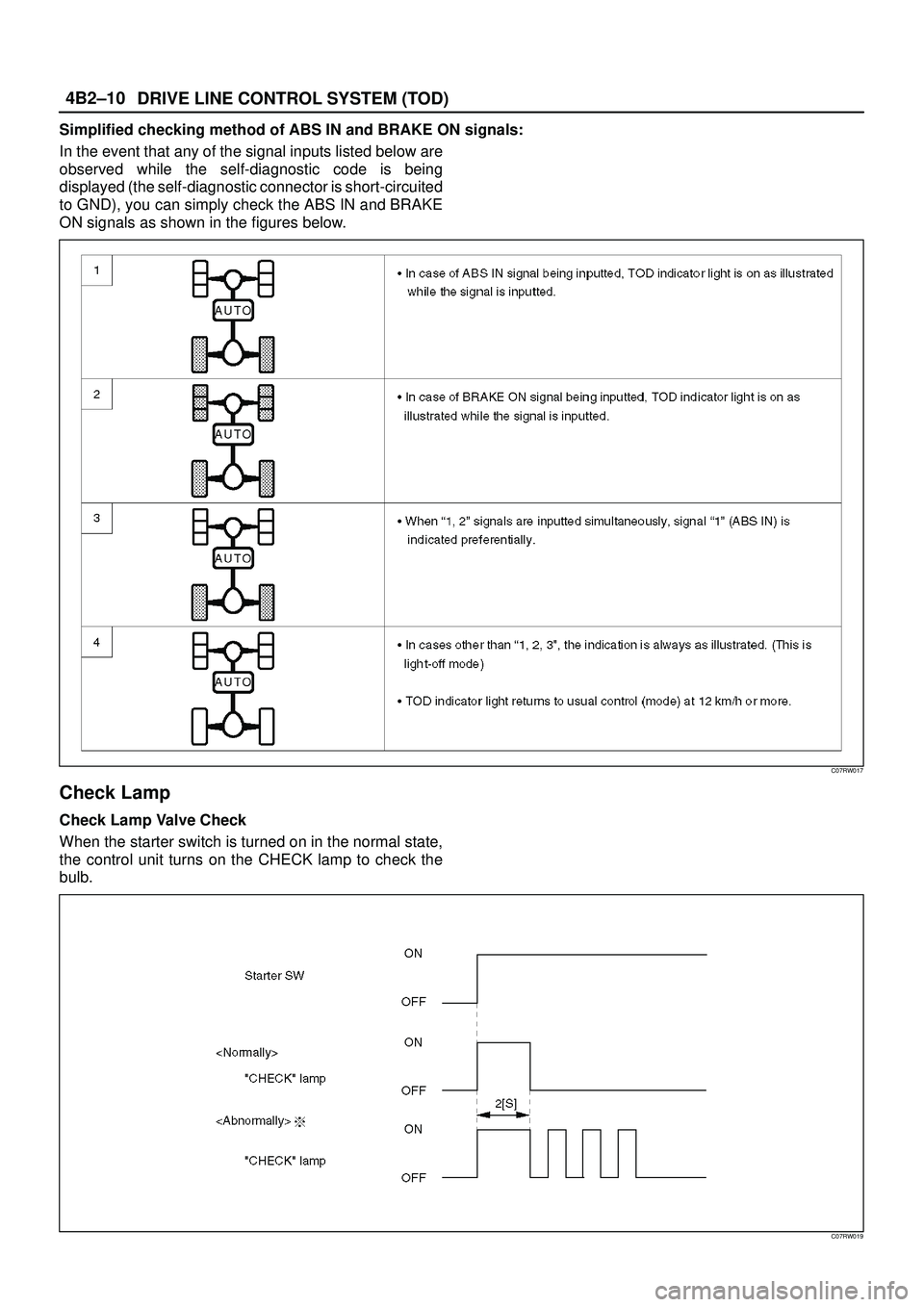
Simplified checking method of ABS IN and BRAKE ON signals:
In the event that any of the signal inputs listed below are
observed while the self-diagnostic code is being
displayed (the self-diagnostic connector is short-circuited
to GND), you can simply check the ABS IN and BRAKE
ON signals as shown in the figures below.
C07RW017
Check Lamp
Check Lamp Valve Check
When the starter switch is turned on in the normal state,
the control unit turns on the CHECK lamp to check the
bulb.
C07RW019
Page 582 of 3573

4B2±11 DRIVE LINE CONTROL SYSTEM (TOD)
The CHECK lamp also has the following functions.
D-G MAP recognition and display (The control unit
displays what type of vehicle, diesel or gasoline
vehicle, it recognizes.)
1. Short-circuit the self-diagnostic connector.
2. Turn on the starter switch. (Displays with respect to
the self-diagnosis begin to appear.)
NOTE: Do not start the engine.
3. Shift the transfer lever to the neutral position between
HIGH and 4L.
4. After all the conditions in 1 through 3 above are met,
set the throttle to the WOT (wide open throttle)
position (i.e., full open position). The display of the
self-diagnosis is temporarily suspended, and the
CHECK lamp begins to display that MAP is
recognized by the TPS (throttle position sensor)
according to the current conditions.NOTE: If the TPS has failed, this function might not work.
1. When the control unit recognizes the vehicle as
gasoline type, the CHECK lamp is turned on for five
seconds and this mode is repeated at an interval of
0.3 second.
2. When the control unit recognizes the vehicle as
diesel type, the CHECK lamp is turned off for five
seconds and this mode is repeated at an interval of
0.3 seconds.
3. Upon completion of step 4, the system resumes the
self-diagnosis. (The self-diagnosis is executed
from the beginning.)
5. Turn off the starter switch once. When above
conditions are met again in the future, the TPS MAP
control can be started.
C04RW010
Page 584 of 3573
4B2±13 DRIVE LINE CONTROL SYSTEM (TOD)
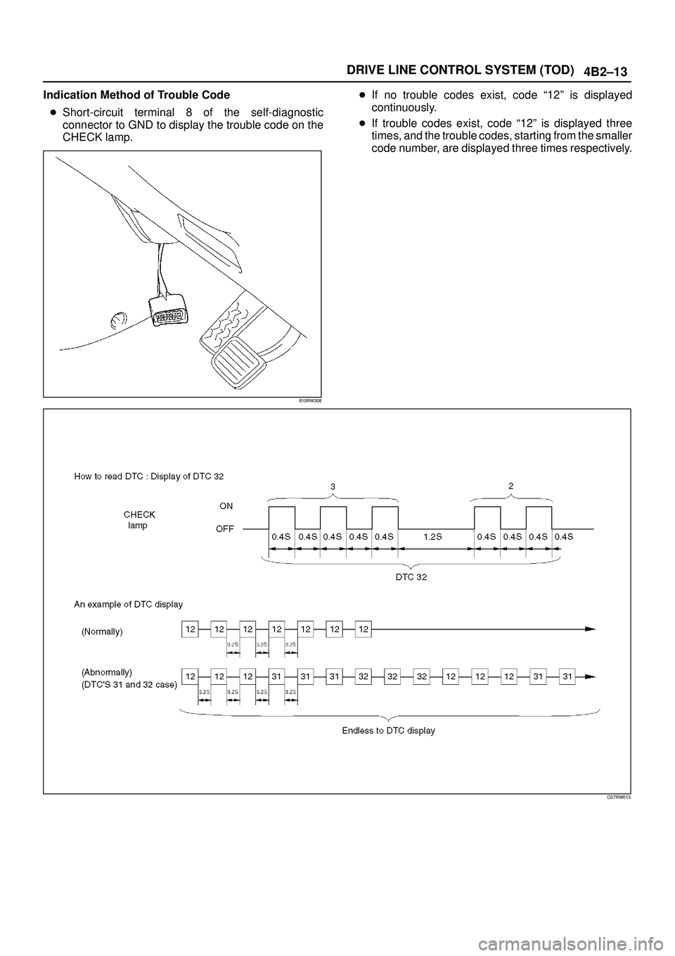
Indication Method of Trouble Code
�Short-circuit terminal 8 of the self-diagnostic
connector to GND to display the trouble code on the
CHECK lamp.
810RW308
�If no trouble codes exist, code ª12º is displayed
continuously.
�If trouble codes exist, code ª12º is displayed three
times, and the trouble codes, starting from the smaller
code number, are displayed three times respectively.
C07RW013
Page 585 of 3573

DRIVE LINE CONTROL SYSTEM (TOD) 4B2±14
How to Clear The Trouble Code
The trouble codes saved to the control unit can be deleted
by the following procedure if the starter switch is being in
the OFF position.
1. Shift the transfer lever to the neutral position between
HIGH and 4L, and short-circuit the self-diagnostic
connector.
NOTE: The neutral position between HIGH and 4L refers
to the point that turns off the TOD indicator lamps.
(However, be sure to check the position before
short-circuiting the self-diagnostic connector.)
C07RW011
2. Turn on the starter switch while maintaining the state
of step 1, and step on the brake pedal five times within
five seconds from the first step on. (Note that ªfive
timesº includes the first step on). (The TOD indicator
lamps display the 4L mode whenever the brake pedal
is stepped on.)
3. If the conditions shown in steps 1 and 2 are met, clear
the trouble codes saved to the control unit. (After the
codes are completely deleted, the code 12 that
indicates the normal condition is continuously
displayed.)
Precautions on Diagnosis
Replacement of Control Unit
The control unit itself rarely fails. In most cases, the
harnesses have failed (e.q. short-circuit) to cause
secondary troubles. Other cases include that the cause
has been unknown due to intermittent occurrence of
troubles and the troubles are removed accidentally along
with replacement of control unit, resulting in misjudgment
of cause. Therefore, before replacing the control unit,
check the connector joints and whether the unspecified
current flows in the control unit due to short-circuit
between harnesses.Trouble Intermittently Observed
Troubles intermittently observed are mostly attributable
to temporary imperfect connection of harnesses and
connectors.
When such troubles are found, check the associated
circuit according to the following procedure.
1. Check whether improper connectors are plugged in
or connector terminals are completely engaged.
2. Check whether the terminals are deformed or
damaged. If yes, remove the deformation or damage
and connect the terminals securely.
3. It is likely that wires in the harness are falsely broken.
Therefore, in examination of failed harness circuit,
shake the harness for check to such extent that the
harness will not be damaged.
Test Run of Filed TOD Vehicle
If the TOD indicator lamps experienced faulty operation
even once in the past, the failed portion can be identified
by use of the procedure ªDiagnosis from Trouble Codesº
or ªTrouble Diagnosis Depending on The Status of TOD
Indicatorº. If the troubles that are only recognized as
abnormal phenomena of the vehicle by the driver are
observed, conduct the test run in the following procedure
to reproduce the faulty phenomena and diagnose the fault
for each phenomenon.
1. Start the engine, and check that the TOD indicator
lamps are turned on for about two seconds for initial
check; the CHECK lamp goes off; and the TOD
indicator lamps display the specified drive mode. (If
the CHECK lamp starts blinking, read the trouble
codes and identify the failed portion.)
2. While keeping the vehicle standstill, operate the 4WD
switch and shift the transfer lever to change the
modes: 2H mode"TOD mode"4L mode"TOD
mode"2H mode. Check that the TOD indicator
lamps correctly display the status whenever the
mode is changed. If the transition status is displayed
during the shift operation, run the vehicle a little to
complete shifting.
3. Slowly start the vehicle in the TOD mode, and add the
power to accelerate to at least 40 km/h and maintain
the speed for about two minutes. Apply the brake to
completely stop the vehicle. Repeat this test pattern
at least three times.
4. Turn the steering to the right end (or left end) in the
TOD mode, and slowly start the vehicle and make a
circle five times. Next, conduct the same test in the 2H
mode.
5. Slowly start the vehicle in the TOD mode, and
accelerate to at least 40 km/h. Keep the established
speed, carefully change the mode in the sequence
ªTOD mode"2H mode "TOD modeº while checking
that the shift is complete in each mode change. After
the test, apply the brake to completely stop the
vehicle.
6. Slowly start the vehicle in the TOD mode, and
accelerate to at least 40 km/h. Apply the brake
strongly so that the ABS works, and completely stop
the vehicle.
Page 595 of 3573
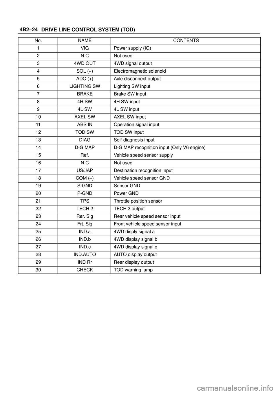
DRIVE LINE CONTROL SYSTEM (TOD) 4B2±24
No.NAMECONTENTS
1VIGPower supply (IG)
2N.CNot used
34WD OUT4WD signal output
4SOL (+)Electromagnetic solenoid
5ADC (+)Axle disconnect output
6LIGHTING SWLighting SW input
7BRAKEBrake SW input
84H SW4H SW input
94L SW4L SW input
10AXEL SWAXEL SW input
11ABS INOperation signal input
12TOD SWTOD SW input
13DIAGSelf-diagnosis input
14D-G MAPD-G MAP recognition input (Only V6 engine)
15Ref.Vehicle speed sensor supply
16N.CNot used
17US/JAPDestination recognition input
18COM (±)Vehicle speed sensor GND
19S-GNDSensor GND
20P-GNDPower GND
21TPSThrottle position sensor
22TECH 2TECH 2 output
23Rer. SigRear vehicle speed sensor input
24Frt. SigFront vehicle speed sensor input
25IND.a4WD disply signal a
26IND.b4WD display signal b
27IND.c4WD display signal c
28IND.AUTOAUTO display output
29IND RrRear display output
30CHECKTOD warning lamp
Page 599 of 3573
DRIVE LINE CONTROL SYSTEM (TOD) 4B2±28
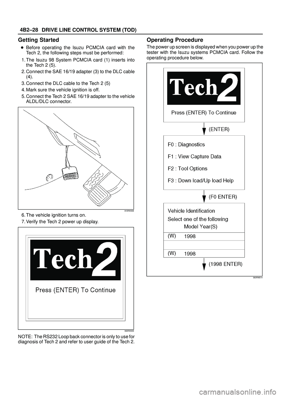
Getting Started
�Before operating the Isuzu PCMCIA card with the
Tech 2, the following steps must be performed:
1. The Isuzu 98 System PCMCIA card (1) inserts into
the Tech 2 (5).
2. Connect the SAE 16/19 adapter (3) to the DLC cable
(4).
3. Connect the DLC cable to the Tech 2 (5)
4. Mark sure the vehicle ignition is off.
5. Connect the Tech 2 SAE 16/19 adapter to the vehicle
ALDL/DLC connector.
810RW308
6. The vehicle ignition turns on.
7. Verify the Tech 2 power up display.
060RW009
NOTE: The RS232 Loop back connector is only to use for
diagnosis of Tech 2 and refer to user guide of the Tech 2.
Operating Procedure
The power up screen is displayed when you power up the
tester with the Isuzu systems PCMCIA card. Follow the
operating procedure below.
060RW014
Page 636 of 3573
4B2±65 DRIVE LINE CONTROL SYSTEM (TOD)
Chart C±14H switch circuit wires are broken or the battery is short-circuited.
Function of circuitÐ
Fail conditionWhen the 4WD SW is 4WD mode.
When the lever is shifted from 4L to HIGH, the 4L mode remains on the indicator and the
TOD mode is displayed without turning off the previous mode.
Indicator lamp status
Transfer position4L <ÐÐ> Neutral <ÐÐ> TOD
D04RW062
Page 642 of 3573
4B2±71 DRIVE LINE CONTROL SYSTEM (TOD)
Chart D±14L switch circuit wires are broken or the battery is short-circuited.
Function of circuitÐ
Fail conditionThe TOD mode is displayed in the neutral position between high and 4L. When the lever
is shifted to the 4L position, the TOD mode is displayed.
Indicator lamp status
Transfer position4LNeutral
D04RW061