Page 211 of 3573
AIR CONDITIONING 1BÐ85
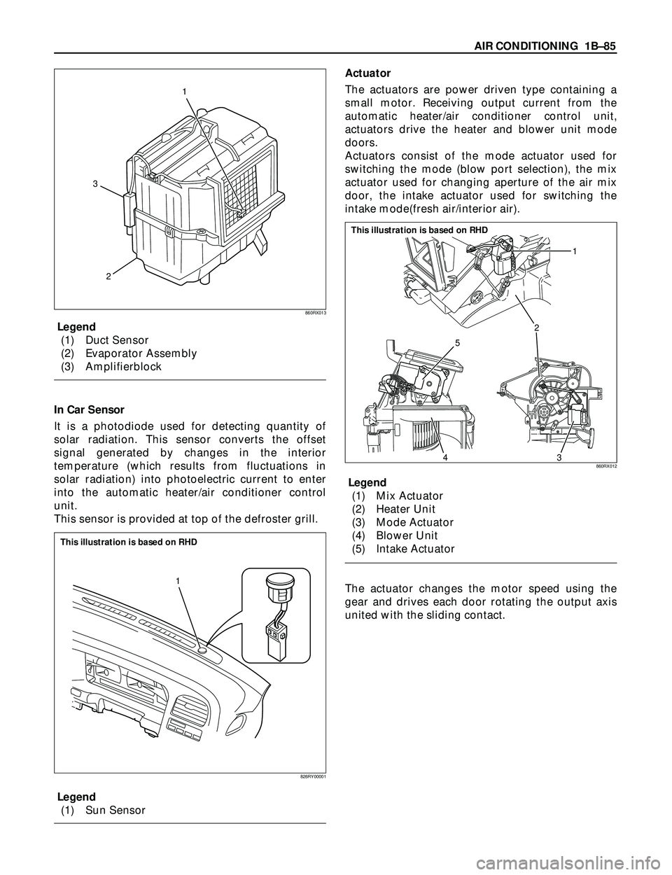
Legend
(1) Duct Sensor
(2) Evaporator Assembly
(3) Amplifierblock
In Car Sensor
It is a photodiode used for detecting quantity of
solar radiation. This sensor converts the offset
signal generated by changes in the interior
temperature (which results from fluctuations in
solar radiation) into photoelectric current to enter
into the automatic heater/air conditioner control
unit.
This sensor is provided at top of the defroster grill.
Legend
(1) Sun SensorActuator
The actuators are power driven type containing a
small motor. Receiving output current from the
automatic heater/air conditioner control unit,
actuators drive the heater and blower unit mode
doors.
Actuators consist of the mode actuator used for
switching the mode (blow port selection), the mix
actuator used for changing aperture of the air mix
door, the intake actuator used for switching the
intake mode(fresh air/interior air).
Legend
(1) Mix Actuator
(2) Heater Unit
(3) Mode Actuator
(4) Blower Unit
(5) Intake Actuator
The actuator changes the motor speed using the
gear and drives each door rotating the output axis
united with the sliding contact.
2 31
860RX013
1
826RY00001
This illustration is based on RHD
2
5
431
860RX012
This illustration is based on RHD
Page 215 of 3573
AIR CONDITIONING 1BÐ89
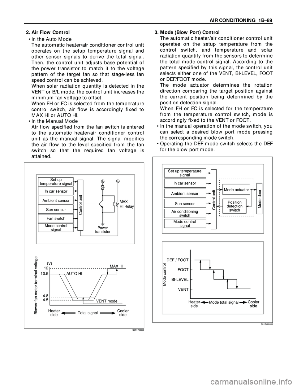
2. Air Flow Control
¥ In the Auto Mode
The automatic heater/air conditioner control unit
operates on the setup temperature signal and
other sensor signals to derive the total signal.
Then, the control unit adjusts base potential of
the power transistor to match it to the voltage
pattern of the target fan so that stage-less fan
speed control can be achieved.
When solar radiation quantity is detected in the
VENT or B/L mode, the control unit increases the
minimum fan voltage to offset.
When FH or FC is selected from the temperature
control switch, air flow is accordingly fixed to
MAX HI or AUTO HI.
¥ In the Manual Mode
Air flow specified from the fan switch is entered
to the automatic heater/air conditioner control
unit as the manual signal. The signal modifies
the air flow to the level specified from the fan
switch so that the required fan voltage is
attained.3. Mode (Blow Port) Control
The automatic heater/air conditioner control unit
operates on the setup temperature from the
control switch, and temperature and solar
radiation quantify from the sensors to determine
the total mode control signal. According to the
pattern specified by this signal, the control unit
selects either one of the VENT, BI-LEVEL, FOOT
or DEF/FOOT mode.
The mode actuator determines the rotation
direction comparing the target position against
the current position being determined by the
position detection signal.
When FH or FC is selected for the temperature
from the temperature control switch, mode is
accordingly fixed to the VENT or FOOT.
¥ In the manual operation of the mode switch, you
can select a desired blow port mode pressing
the corresponding mode switch.
¥ Operating the DEF mode switch selects the DEF
for the blow port mode.
4.512
(V)
M
MAX
HI Relay
Power
transistor
4.8 10.5MAX HI Set up
temperature signal
Control unit
In car sensor
Ambient sensor
Sun sensor
Mode control
signal Fan switch
AUTO HI
Heater
sideCooler
side Total signalVENT mode
Blower fan motor terminal voltage
C01RY00008
Mode control
DEF / FOOTSet up temperature
signal
Mode actuator
Mode doorPosition
detection
switch
Control unit
In car sensor
Sun sensor
Air conditioning
switch
Mode control
signal Ambient sensor
FOOT
BI-LEVEL
VENT
Heater
sideCooler
side Mode total signal
C01RY00009
Page 224 of 3573
1BÐ98 AIR CONDITIONING
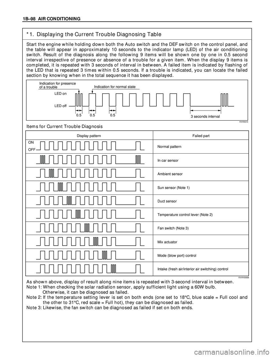
*1. Displaying the Current Trouble Diagnosing Table
Start the engine while holding down both the Auto switch and the DEF switch on the control panel, and
the table will appear in approximately 10 seconds to the indicator lamp (LED) of the air conditioning
switch. Result of the diagnosis along the following 9 items will be shown one by one in 0.5 second
interval irrespective of presence or absence of a trouble for a given item. When the display 9 items is
completed, it is repeated with 3 seconds of interval in between. A failed item is indicated by flashing of
the LED that is repeated 3 times within 0.5 seconds. If a trouble is indicated, you can locate the failed
section by knowing when in the total sequence it has been displayed.
Items for Current Trouble Diagnosis
As shown above, display of result along nine items is repeated with 3-second interval in between.
Note 1: When checking the solar radiation sensor, apply sufficient light using a 60W bulb.
Otherwise, it can be diagnosed as failed.
Note 2: If the temperature setting lever is set on both ends (one set to 18¡C, blue scale = Full cool and
the other to 31¡C, red scale = Full hot), they can be diagnosed as failed.
Note 3: Likewise, the fan switch can be diagnosed as failed if set on both ends.
LED on
LED off Indication for presence
of a troubleIndication for normal state
0.5 0.5 0.5
3 seconds interval
ON
OFF
Display pattern Failed part
Normal pattern
In car sensor
Ambient sensor
Sun sensor (Note 1)
Duct sensor
Temperature control lever (Note 2)
Fan switch (Note 3)
Mix actuator
Mode (blow port) control
Intake (fresh air/interior air switching) control
F01RX010
F01RY00008
Page 253 of 3573
AIR CONDITIONING 1BÐ127
In Car Sensor
Legend
(1) In Car Sensor
(2) Automatic Heater / Air Conditioner Control
Unit
Removal
1. Disconnect the battery ground cable.
2. Remove the automatic heater / air conditioner
control unit.
·Refer to the automatic heater / air conditioner
control unit section.
3. Remove in car sensor.
Installation
To install, follow the removal step in the reverse
order.
Ambient Sensor
Legend
(1) Ambient Sensor
(2) Sensor Connector
(3) Radiator Grill
Removal
1. Disconnect the battery ground cable.
2. Remove radiator grille.
·Refer to Radiator Grille in Body Structure
section.
3. Disconnect the ambient sensor connector.
4. Remove the ambient sensor.
Installation
To install, follow the removal step in the reverse
order.
����
��
;&9&-
"650
"�$0''"
650-0)*
21
865RY00006
12
3
875RY00001
Page 471 of 3573

4A2A±4
DIFFERENTIAL (REAR 220mm)
Axle Housing
Axle Housing and Associated Parts
420RW022
Legend
(1) Coil Spring and Insulator
(2) Axle Housing Assembly
(3) ABS Speed Sensor and Harness(if equipped)
(4) Nut
(5) Parking Brake Cable
(6) Bolt and Nut
(7) Antilock Brake System (ABS) Connector and
Bracket (if equipped)
(8) Bolt and Nut(9) Nut
(10) Differential Assembly
(11) Axle Shaft Assembly
(12) Brake Disc
(13) Brake Pipe
(14) Brake Caliper
(15) Nut
(16) Breather Hose
(17) Flare Nut
Removal
1. Raise the vehicle and support it with suitable safety
stands.
The hoist must remain under the rear axle housing.
2. Drain brake fluid. Refer to Hydraulic Brakes in Brake
section.
3. Remove rear wheels and tires. Refer to Wheel in
Suspension section.4. Remove propeller shaft. Refer to Rear Propeller
Shaft in this section.
5. Drain the rear axle oil into a proper container.
6. Remove parking brake cable, release the connection
between the cable fixing clip equalizer. Refer to
Parking Brakes in Brake section.
7. Move the clip aside and pull out the breather hose.
Page 475 of 3573
4A2A±8
DIFFERENTIAL (REAR 220mm)
Differential Assembly
Differential Assembly and Associated Parts
425RW055
Legend
(1) Bolt and Nut
(2) Axle Shaft Assembly(3) Parking Brake Cable
(4) Differential Assembly
(5) Nut
Removal
1. Jack up and support the frame with stands.
2. Remove the wheel and tire. Refer to Wheel in
Steering section.
3. Drain the differential oil.
4. Remove the propeller shaft. Refer to Rear Propeller
Shaft in this section.
5. Remove the ABS speed sensor(ABS model only).
Refer to 4±Wheel Anti±lock Brake System (ABS) in
Brake section.6. Remove the parking brake cable fastening clip and
disconnect the equalizer section. Refer to Parking
Brakes in Brake section.
7. Remove the bearing holder fixing nuts.
8. Remove axle shaft assembly, be sure not to damage
the oil seal by axle shaft.
9. Remove differential carrier mounting bolts and nuts.
10. Remove differential assembly.
Page 507 of 3573

4A2B±4DIFFERENTIAL (REAR 244mm)
Axle Housing
Axle Housing and Associated Parts
420RW001
Legend
(1) Coil Spring and Insulator
(2) Axle Housing Assembly
(3) ABS Speed Sensor and Harness (if so
equipped)
(4) Nut
(5) Parking Brake Cable
(6) Bolt and Nut
(7) Antilock Brake System (ABS) Connector and
Bracket (if so equipped)(8) Bolt and Nut
(9) Nut
(10) Differential Assembly
(11) Axle Shaft Assembly
(12) Brake Disc
(13) Brake Pipe
(14) Brake Caliper
(15) Nut
(16) Breather Hose
(17) Flare Nut
Removal
1. Raise the vehicle and support it with suitable safety
stands.
The hoist must remain under the rear axle housing.
2. Drain brake fluid. Refer to Hydraulic Brakes in Brakes
section.
3. Remove rear wheels and tires. Refer to Wheel in
Suspension section.4. Remove propeller shaft. Refer to Rear Propeller
Shaft in this section.
5. Drain the rear axle oil into a proper container.
6. Remove parking brake cable, release the connection
between the cable fixing clip equalizer. Refer to
Parking Brakes in Brakes section.
7. Move the clip aside and pull out the breather hose.
Page 511 of 3573
4A2B±8DIFFERENTIAL (REAR 244mm)
Differential Assembly
Differential Assembly and Associated Parts
425RW044
Legend
(1) Bolt and Nut
(2) Axle Shaft Assembly(3) Parking Brake Cable
(4) Differential Assembly
(5) Nut
Removal
1. Jack up and support the frame with stands.
2. Remove the wheel and tire. Refer to Wheel in
Steering section.
3. Drain the differential oil.
4. Remove the propeller shaft. Refer to Rear Propeller
Shaft in this section.
5. Remove the ABS speed sensor. Refer to Anti±lock
Brake System in Brakes section.6. Remove the parking brake cable fastening clip and
disconnect the equalizer section. Refer to Parking
Brakes in Brake section.
7. Remove the bearing holder fixing nuts.
8. Remove axle shaft assembly, be sure not to damage
the oil seal by axle shaft.
9. Remove differential carrier mounting bolts and nuts.
10. Remove differential assembly.


