Page 558 of 3573

4B1±25 DRIVE LINE CONTROL SYSTEM (SHIFT ON THE FLY)
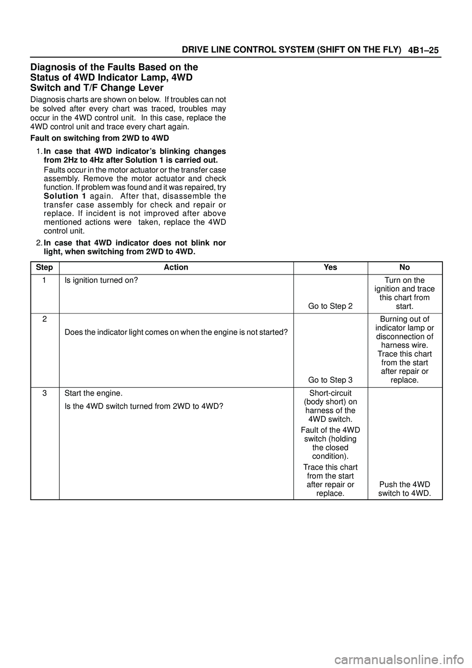
Diagnosis of the Faults Based on the
Status of 4WD Indicator Lamp, 4WD
Switch and T/F Change Lever
Diagnosis charts are shown on below. If troubles can not
be solved after every chart was traced, troubles may
occur in the 4WD control unit. In this case, replace the
4WD control unit and trace every chart again.
Fault on switching from 2WD to 4WD
1.In case that 4WD indicator's blinking changes
from 2Hz to 4Hz after Solution 1 is carried out.
Faults occur in the motor actuator or the transfer case
assembly. Remove the motor actuator and check
function. If problem was found and it was repaired, try
Solution 1 again. After that, disassemble the
transfer case assembly for check and repair or
replace. If incident is not improved after above
mentioned actions were taken, replace the 4WD
control unit.
2.In case that 4WD indicator does not blink nor
light, when switching from 2WD to 4WD.
Step
ActionYe sNo
1Is ignition turned on?
Go to Step 2
Turn on the
ignition and trace
this chart from
start.
2
Does the indicator light comes on when the engine is not started?
Go to Step 3
Burning out of
indicator lamp or
disconnection of
harness wire.
Trace this chart
from the start
after repair or
replace.
3Start the engine.
Is the 4WD switch turned from 2WD to 4WD?Short-circuit
(body short) on
harness of the
4WD switch.
Fault of the 4WD
switch (holding
the closed
condition).
Trace this chart
from the start
after repair or
replace.
Push the 4WD
switch to 4WD.
Page 559 of 3573

4B1±26
DRIVE LINE CONTROL SYSTEM (SHIFT ON THE FLY)
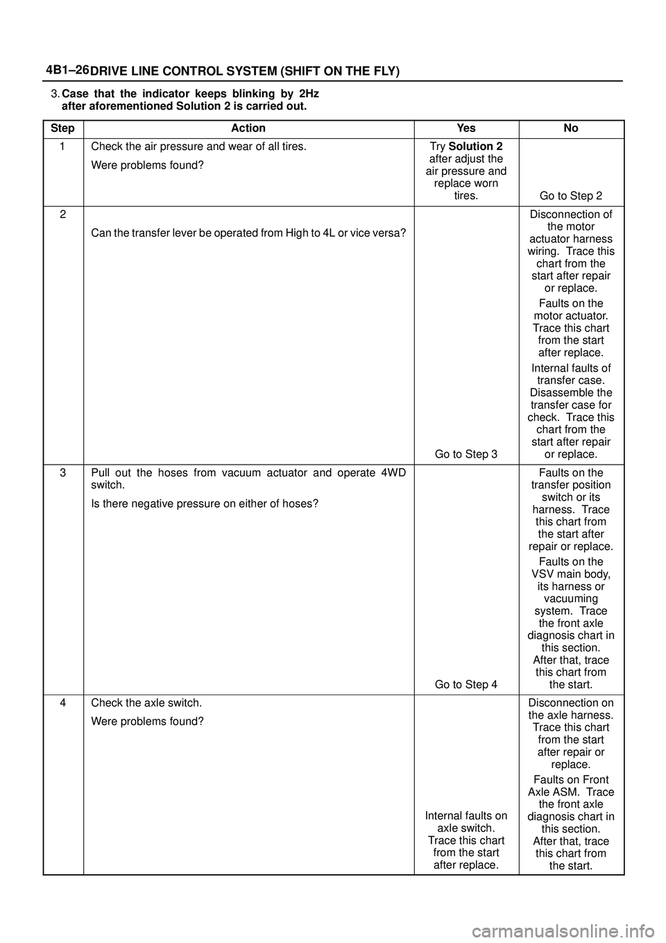
3.Case that the indicator keeps blinking by 2Hz
after aforementioned Solution 2 is carried out.
Step
ActionYe sNo
1Check the air pressure and wear of all tires.
Were problems found?Try Solution 2
after adjust the
air pressure and
replace worn
tires.
Go to Step 2
2
Can the transfer lever be operated from High to 4L or vice versa?
Go to Step 3
Disconnection of
the motor
actuator harness
wiring. Trace this
chart from the
start after repair
or replace.
Faults on the
motor actuator.
Trace this chart
from the start
after replace.
Internal faults of
transfer case.
Disassemble the
transfer case for
check. Trace this
chart from the
start after repair
or replace.
3Pull out the hoses from vacuum actuator and operate 4WD
switch.
Is there negative pressure on either of hoses?
Go to Step 4
Faults on the
transfer position
switch or its
harness. Trace
this chart from
the start after
repair or replace.
Faults on the
VSV main body,
its harness or
vacuuming
system. Trace
the front axle
diagnosis chart in
this section.
After that, trace
this chart from
the start.
4Check the axle switch.
Were problems found?
Internal faults on
axle switch.
Trace this chart
from the start
after replace.
Disconnection on
the axle harness.
Trace this chart
from the start
after repair or
replace.
Faults on Front
Axle ASM. Trace
the front axle
diagnosis chart in
this section.
After that, trace
this chart from
the start.
Page 560 of 3573
4B1±27 DRIVE LINE CONTROL SYSTEM (SHIFT ON THE FLY)
Fault on switching from 4WD to 2WD
1.Case that indicator does not blink nor turn out.
Step
ActionYe sNo
1
Does the indicator turn out by ignition off?Go to Step 2
Short circuit of
the indicator
harness.
2
Is the 4WD switch on 2WD position?
Disconnection on
the 4WD switch
harness or
breakdown of the
4WD switch in
open state.
Trace this chart
from the start
after repair or
replace.
Turn the 4WD
switch to 2WD
position. Trace
this chart from
the start.
Page 561 of 3573

4B1±28
DRIVE LINE CONTROL SYSTEM (SHIFT ON THE FLY)
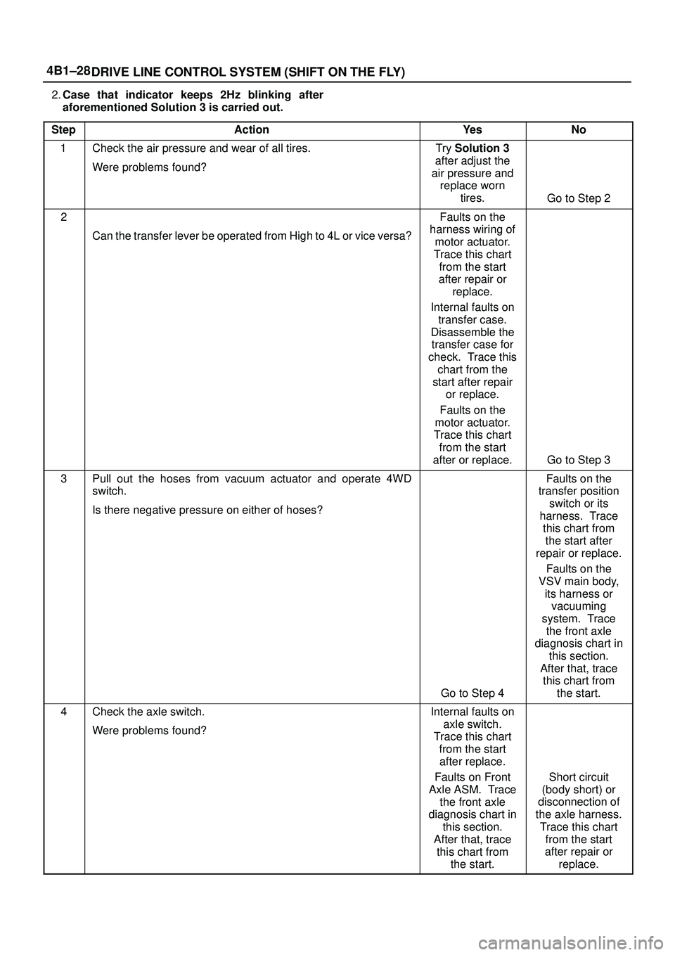
2.Case that indicator keeps 2Hz blinking after
aforementioned Solution 3 is carried out.
Step
ActionYe sNo
1Check the air pressure and wear of all tires.
Were problems found?Try Solution 3
after adjust the
air pressure and
replace worn
tires.
Go to Step 2
2
Can the transfer lever be operated from High to 4L or vice versa?
Faults on the
harness wiring of
motor actuator.
Trace this chart
from the start
after repair or
replace.
Internal faults on
transfer case.
Disassemble the
transfer case for
check. Trace this
chart from the
start after repair
or replace.
Faults on the
motor actuator.
Trace this chart
from the start
after or replace.
Go to Step 3
3Pull out the hoses from vacuum actuator and operate 4WD
switch.
Is there negative pressure on either of hoses?
Go to Step 4
Faults on the
transfer position
switch or its
harness. Trace
this chart from
the start after
repair or replace.
Faults on the
VSV main body,
its harness or
vacuuming
system. Trace
the front axle
diagnosis chart in
this section.
After that, trace
this chart from
the start.
4Check the axle switch.
Were problems found?Internal faults on
axle switch.
Trace this chart
from the start
after replace.
Faults on Front
Axle ASM. Trace
the front axle
diagnosis chart in
this section.
After that, trace
this chart from
the start.
Short circuit
(body short) or
disconnection of
the axle harness.
Trace this chart
from the start
after repair or
replace.
Page 562 of 3573
4B1±29 DRIVE LINE CONTROL SYSTEM (SHIFT ON THE FLY)
3.Case that indicator's blinking changes to 4Hz
after aforementioned Solution 4 is carried out.
Step
ActionYe sNo
1
Can the transfer lever be operated from High to 4L or vice versa?
Faults on the
harness wiring of
motor actuator.
Trace this chart
from the start
after repair or
replace.
Faults on the
motor actuator.
Trace this chart
from the start
after replace.
Internal faults on
transfer case.
Disassemble the
transfer case for
check. Trace this
chart from the
start after repair
or replace.
Faults on the
4WD control unit.
Trace this chart
from the start
after replace.
Page 563 of 3573

4B1±30
DRIVE LINE CONTROL SYSTEM (SHIFT ON THE FLY)
Front Axle Diagnosis
�When the 4WD switch is operated from 4H to 2H,
indicator light does not go out.
Step
ActionYe sNo
1Drive slow 100 Ð 200m after a few minutesº idling.
Has indicator light gone out?
All right.Go to Step 2
2Jack up front tires.
Does the right side of front wheel rotate when the left side of front
wheel is rotated?
Go to Step 4Go to Step 3
31. Check the actuator switch.
2. Check the circuit to indicator.
Was a problem found?
Trace this chart
from the start
after repair or
replace.
Disassemble axle
ASM for check.
Trace this chart
from the start
after repair or
replace.
41. Check the VSV valve.
2. Check the circuit to VSV valve.
Was a problem found?Trace this chart
from the start
after repair or
replace.
Go to Step 5
5Is vacuum piping all right? (tank, hose, & pipe damage or trouble)
Go to Step 6
Trace this chart
from the start
after repair or
replace.
6Does actuator work all right?
Trace this chart
from the start.
Disassemble axle
ASM for check.
Trace this chart
from the start
after repair or
replace.
Page 564 of 3573

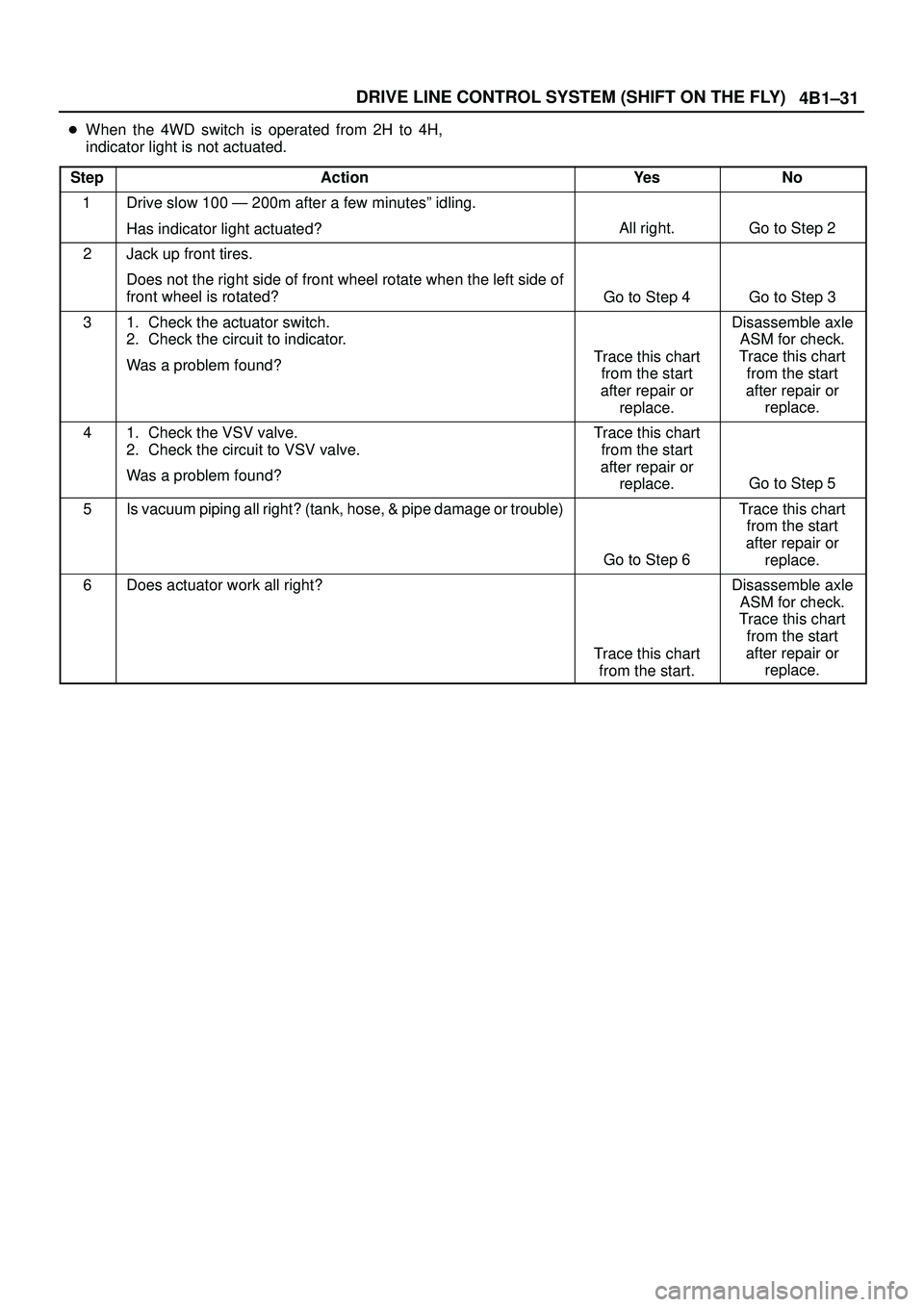
4B1±31 DRIVE LINE CONTROL SYSTEM (SHIFT ON THE FLY)
�When the 4WD switch is operated from 2H to 4H,
indicator light is not actuated.
Step
ActionYe sNo
1Drive slow 100 Ð 200m after a few minutesº idling.
Has indicator light actuated?
All right.Go to Step 2
2Jack up front tires.
Does not the right side of front wheel rotate when the left side of
front wheel is rotated?
Go to Step 4Go to Step 3
31. Check the actuator switch.
2. Check the circuit to indicator.
Was a problem found?
Trace this chart
from the start
after repair or
replace.
Disassemble axle
ASM for check.
Trace this chart
from the start
after repair or
replace.
41. Check the VSV valve.
2. Check the circuit to VSV valve.
Was a problem found?Trace this chart
from the start
after repair or
replace.
Go to Step 5
5Is vacuum piping all right? (tank, hose, & pipe damage or trouble)
Go to Step 6
Trace this chart
from the start
after repair or
replace.
6Does actuator work all right?
Trace this chart
from the start.
Disassemble axle
ASM for check.
Trace this chart
from the start
after repair or
replace.
Page 568 of 3573
4B1±35 DRIVE LINE CONTROL SYSTEM (SHIFT ON THE FLY)
1. Disassemble the motor actuator from transfer rear
case.
412RW037
Legend
(3) Shift Rod
(4) Connector
2. Connect the terminals as shown in figure.
Shift rod of the motor actuator moves and stops
at 4WD position.
412RW038
Legend
(1) 2WD
(2) 4WD
(3) Shift Rod
(4) Connector
3. Connect the terminals as shown in figure.Shift rod of the motor actuator moves and stops
at 2WD position.
412RW039
Legend
(1) 2WD
(2) 4WD
(3) Shift Rod
(4) Connector
4. If 2) and 3) fail, replace with a new motor actuator.
Transfer Position Switch
412RW040
Legend
(1) Ball
1. With ball being free.
A±B : There is continuity.
2. With ball forced into the switch.
A±B : No continuity.
3. If 1) and 2) fail, replace with a new switch.