1998 ISUZU TROOPER Coolant system
[x] Cancel search: Coolant systemPage 1835 of 3573
6B – 2 ENGINE COOLING
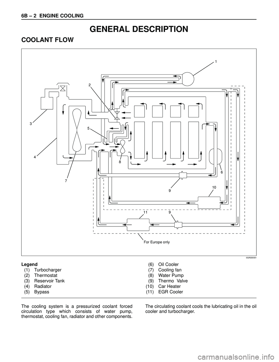
Legend
(1) Turbocharger
(2) Thermostat
(3) Reservoir Tank
(4) Radiator
(5) Bypass(6) Oil Cooler
(7) Cooling fan
(8) Water Pump
(9) Thermo Valve
(10) Car Heater
(11) EGR Cooler
GENERAL DESCRIPTION
COOLANT FLOW
1
6
9
9
For Europe only
10
8
4
32
5
7
11
032R200001
The cooling system is a pressurized coolant forced
circulation type which consists of water pump,
thermostat, cooling fan, radiator and other components. The circulating coolant cools the lubricating oil in the oil
cooler and turbocharger.
Page 1837 of 3573
6B – 4 ENGINE COOLING
ANTI-FREEZE SOLUTION
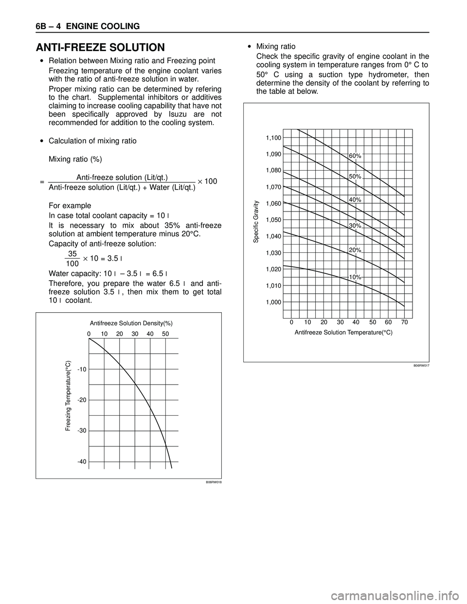
•Relation between Mixing ratio and Freezing point
Freezing temperature of the engine coolant varies
with the ratio of anti-freeze solution in water.
Proper mixing ratio can be determined by refering
to the chart. Supplemental inhibitors or additives
claiming to increase cooling capability that have not
been specifically approved by Isuzu are not
recommended for addition to the cooling system.
•Calculation of mixing ratio
Mixing ratio (%)
=Anti-freeze solution (Lit/qt.)
×100
Anti-freeze solution (Lit/qt.) + Water (Lit/qt.)
For example
In case total coolant capacity = 10
l
It is necessary to mix about 35% anti-freeze
solution at ambient temperature minus 20°C.
Capacity of anti-freeze solution:
35
×10 = 3.5
l100
Water capacity: 10
l– 3.5 l= 6.5 l
Therefore, you prepare the water 6.5 land anti-
freeze solution 3.5
l, then mix them to get total
10
lcoolant.•Mixing ratio
Check the specific gravity of engine coolant in the
cooling system in temperature ranges from 0°C to
50°C using a suction type hydrometer, then
determine the density of the coolant by referring to
the table at below.
-1010 0
Freezing Temperature(°C)
20 30 Antifreeze Solution Density(%)
40 50
-20
-30
-40
B06RW018
1,100
20 10 30 4060%
50%
40%
20%
10%
30%
Antifreeze Solution Temperature(°C) 50 60 70 0
Specific Gravity
1,090
1,080
1,070
1,060
1,050
1,040
1,030
1,020
1,010
1,000
B06RW017
Page 1838 of 3573
ENGINE COOLING 6B – 5
ENGINE COOLANT CHANGE
PROCEDURE
1. To change engine coolant, make sure that the
engine is cool.
WARNING:
When the coolant is heated to a high temperature,
be sure not to loosen or remove the radiator cap.
Otherwise you might get scalded by hot vapor or
boiling water. To open the radiator cap, put a piece
of thick cloth on the cap and loosen the cap slowly
to reduce the pressure once the coolant has
become cooler.
2. Open radiator cap and drain the cooling system by
loosening the drain valve on the radiator and on the
cylinder body.
NOTE: For best results it is suggested that the engine
cooling system be flushed at least once a year. It is
advisable to flush the interior of the cooling system
including the radiator before using anti-freeze
(ethylene-glycol based).
Replace damaged rubber hoses as the engine anti-
freeze coolant is liable to leak out even minor cracks.
Isuzu recommends using Isuzu genuine anti-freeze
(ethylene-glycol based) or equivalent, for the cooling
system and not add any inhibitors or additives.
CAUTION:
A failure to correctly fill the engine cooling system
in changing or topping off coolant may sometimes
cause the coolant to overflow from the filler neck
even before the engine and radiator are completely
full.
If the engine runs under this condition, shortage of
coolant may possibly result in engine overheating.
To avoid such trouble, the following precautions
should be taken in filling the system.
3. To refill engine coolant, pour coolant up to filler neck
using a filling hose which is smaller in outside
diameter than the filler neck. Otherwise air between
the filler neck and the filling hose will block entry,
preventing the system from completely filling up.
4. Keep a filling rate of 9 liter/min. or less. Filling over
this maximum rate may force air inside the engine
and radiator.
And also, the coolant overflow will increase, making
it difficult to determine whether or not the system is
completely full.
5. After filling the system full, pull out the filling hose
and check to see if air trapped in the system is
dislodged and the coolant level goes down. Should
the coolant level go down, repeat topping-off until
there is no more drop in the coolant level.
6. Directly after filling the radiator, fill the reservoir to
the maximum level.
7. Install and tighten radiator cap and start the engine.
After idling for 2 to 3 minutes, stop the engine and
reopen radiator cap. If the water level is lower,
replenish.WARNING:
When the coolant is heated to a high temperature,
be sure not to loosen or remove the radiator cap.
Otherwise you might get scalded by hot vapor or
boiling water. To open the radiator cap, put a piece
of thick cloth on the cap and loosen the cap slowly
to reduce the pressure once the coolant has
become cooler.
8. After tightening radiator cap, warm up the engine at
about 2,000 rpm.
Set heater adjustment to the highest temperature
position, and let the coolant circulate also into
heater water system.
9. Check to see the thermostat has opened by the
needle position of a water thermometer, conduct a
5-minute idle again and stop the engine.
10. When the engine has been cooled, check filler neck
for water level and replenish if required. Should
extreme shortage of coolant be found, check the
coolant system and reservoir tank hose for leakage.
11. Fill the coolant into the reservoir tank up to “MAX”
line.
Page 1843 of 3573
6B – 10 ENGINE COOLING
Checking for Coolant Leakage
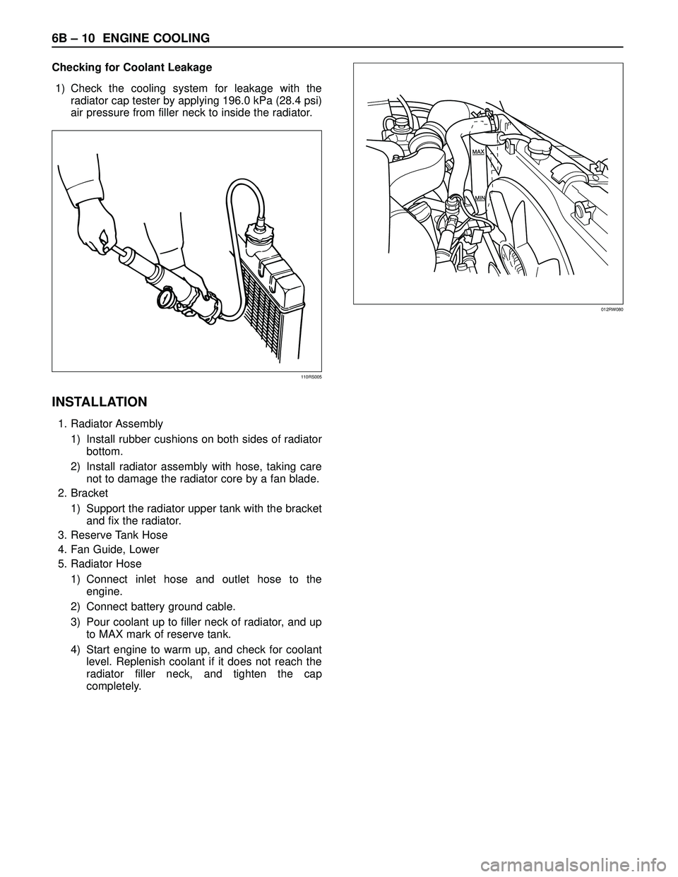
1) Check the cooling system for leakage with the
radiator cap tester by applying 196.0 kPa (28.4 psi)
air pressure from filler neck to inside the radiator.
INSTALLATION
1. Radiator Assembly
1) Install rubber cushions on both sides of radiator
bottom.
2) Install radiator assembly with hose, taking care
not to damage the radiator core by a fan blade.
2. Bracket
1) Support the radiator upper tank with the bracket
and fix the radiator.
3. Reserve Tank Hose
4. Fan Guide, Lower
5. Radiator Hose
1) Connect inlet hose and outlet hose to the
engine.
2) Connect battery ground cable.
3) Pour coolant up to filler neck of radiator, and up
to MAX mark of reserve tank.
4) Start engine to warm up, and check for coolant
level. Replenish coolant if it does not reach the
radiator filler neck, and tighten the cap
completely.
110RS005
012RW080
Page 1890 of 3573
ENGINE ELECTRICAL 6D – 23
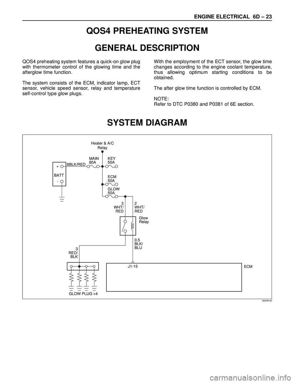
QOS4 PREHEATING SYSTEM
GENERAL DESCRIPTION
QOS4 preheating system features a quick-on glow plug
with thermometer control of the glowing time and the
afterglow time function.
The system consists of the ECM, indicator lamp, ECT
sensor, vehicle speed sensor, relay and temperature
self-control type glow plugs.With the employment of the ECT sensor, the glow time
changes according to the engine coolant temperature,
thus allowing optimum starting conditions to be
obtained.
The after glow time function is controlled by ECM.
NOTE:
Refer to DTC P0380 and P0381 of 6E section.
SYSTEM DIAGRAM
+
-KEY
50A
ECM
50A
GLOW
50A
2
WHT/
RED
0.5
BLK/
BLU
ECM J1-15 3
WHT/
RED
3
RED/
BLKMAIN
80A
8BLK/RED
Glow
Relay
GLOW PLUG 4
BATTHeater & A/C
Relay
060RW132
Page 1895 of 3573
6E±2
4JX1±TC ENGINE DRIVEABILITY AND EMISSIONS
Circuit Description 6E±56. . . . . . . . . . . . . . . . . . . . .
Action Taken When the DTC Sets 6E±56. . . . . . .
Conditions for Clearing the MIL/DTC 6E±56. . . . .
Diagnostic Aids 6E±56. . . . . . . . . . . . . . . . . . . . . . . .
Diagnostic Trouble Code (DTC) P0108
(Flash DTC 34)
MAP Sensor Circuit High Voltage 6E±58. . . . . . . . .
Circuit Description 6E±58. . . . . . . . . . . . . . . . . . . . .
Action Taken When the DTC Sets 6E±58. . . . . . .
Conditions for Clearing the MIL/DTC 6E±58. . . . .
Diagnostic Aids 6E±58. . . . . . . . . . . . . . . . . . . . . . . .
Diagnostic Trouble Code (DTC) P0112
(Flash DTC 23) IAT Sensor Circuit Low
Voltage 6E±60. . . . . . . . . . . . . . . . . . . . . . . . . . . . . . . .
Circuit Description 6E±60. . . . . . . . . . . . . . . . . . . . .
Action Taken When the DTC Sets 6E±60. . . . . . .
Conditions for Clearing the MIL/DTC 6E±60. . . . .
Diagnostic Aids 6E±60. . . . . . . . . . . . . . . . . . . . . . . .
Test Description 6E±61. . . . . . . . . . . . . . . . . . . . . . .
Intake Air Temperature Sensor 6E±61. . . . . . . . . .
Diagnostic Trouble Code (DTC) P0113
(Flash DTC 23) IAT Sensor Circuit High
Voltage 6E±62. . . . . . . . . . . . . . . . . . . . . . . . . . . . . . . .
Circuit Description 6E±62. . . . . . . . . . . . . . . . . . . . .
Action Taken When the DTC Sets 6E±62. . . . . . .
Conditions for Clearing the MIL/DTC 6E±62. . . . .
Diagnostic Aids 6E±62. . . . . . . . . . . . . . . . . . . . . . . .
Test Description 6E±63. . . . . . . . . . . . . . . . . . . . . . .
Manifold Air Temperature Sensor 6E±63. . . . . . . .
Diagnostic Trouble Code (DTC) P0117
(Flash DTC 14) ECT Sensor Low Voltage 6E±65.
Circuit Description 6E±65. . . . . . . . . . . . . . . . . . . . .
Action Taken When the DTC Sets 6E±65. . . . . . .
Conditions for Clearing the MIL/DTC 6E±65. . . . .
Diagnostic Aids 6E±65. . . . . . . . . . . . . . . . . . . . . . . .
Test Description 6E±65. . . . . . . . . . . . . . . . . . . . . . .
Engine Coolant Temperature Sensor 6E±66. . . . .
Diagnostic Trouble Code (DTC) P0118
(Flash DTC 14) ECT Sensor High Voltage 6E±67.
Circuit Description 6E±67. . . . . . . . . . . . . . . . . . . . .
Action Taken When the DTC Sets 6E±67. . . . . . .
Conditions for Clearing the MIL/DTC 6E±67. . . . .
Diagnostic Aids 6E±67. . . . . . . . . . . . . . . . . . . . . . . .
Test Description 6E±68. . . . . . . . . . . . . . . . . . . . . . .
Engine Coolant Temperature Sensor 6E±68. . . . .
Diagnostic Trouble Code (DTC) P0121
(Flash DTC 33) AP Sensor Rationality 6E±70. . . . .
Circuit Description 6E±70. . . . . . . . . . . . . . . . . . . . .
Action Taken When the DTC Sets 6E±70. . . . . . .
Conditions for Clearing the MIL/DTC 6E±70. . . . .
Diagnostic Aids 6E±70. . . . . . . . . . . . . . . . . . . . . . . .
Diagnostic Trouble Code (DTC) P0122
(Flash DTC 21) AP Sensor Low Voltage 6E±72. . .
Circuit Description 6E±72. . . . . . . . . . . . . . . . . . . . . Action Taken When the DTC Sets 6E±72. . . . . . .
Conditions for Clearing the MIL/DTC 6E±72. . . . .
Diagnostic Aids 6E±72. . . . . . . . . . . . . . . . . . . . . . . .
Diagnostic Trouble Code (DTC) P0123
(Flash DTC 21) AP Sensor High Voltage 6E±75. . .
Circuit Description 6E±75. . . . . . . . . . . . . . . . . . . . .
Action Taken When the DTC Sets 6E±75. . . . . . .
Conditions for Clearing the MIL/DTC 6E±75. . . . .
Diagnostic Aids 6E±75. . . . . . . . . . . . . . . . . . . . . . . .
Test Description 6E±75. . . . . . . . . . . . . . . . . . . . . . .
Diagnostic Trouble Code (DTC) P0182
(Flash DTC 15) FT Sensor Low Voltage 6E±78. . .
Circuit Description 6E±78. . . . . . . . . . . . . . . . . . . . .
Action Taken When the DTC Sets 6E±78. . . . . . .
Conditions for Clearing the MIL/DTC 6E±78. . . . .
Diagnostic Aids 6E±78. . . . . . . . . . . . . . . . . . . . . . . .
Test Description 6E±78. . . . . . . . . . . . . . . . . . . . . . .
Diagnostic Trouble Code (DTC) P0183
(Flash DTC 15) FT Sensor High Voltage 6E±80. . .
Circuit Description 6E±80. . . . . . . . . . . . . . . . . . . . .
Action Taken When the DTC Sets 6E±80. . . . . . .
Conditions for Clearing the MIL/DTC 6E±80. . . . .
Diagnostic Aids 6E±80. . . . . . . . . . . . . . . . . . . . . . . .
Test Description 6E±80. . . . . . . . . . . . . . . . . . . . . . .
Diagnostic Trouble Code (DTC) P0192
(Flash DTC 63) Rail Pressure Sensor Low
Voltage 6E±82. . . . . . . . . . . . . . . . . . . . . . . . . . . . . . . .
Circuit Description 6E±82. . . . . . . . . . . . . . . . . . . . .
Action Taken When the DTC Sets 6E±82. . . . . . .
Conditions for Clearing the MIL/DTC 6E±82. . . . .
Diagnostic Aids 6E±82. . . . . . . . . . . . . . . . . . . . . . . .
Diagnostic Trouble Code (DTC) P0193
(Flash DTC 63) Rail Pressure Sensor
High Voltage 6E±84. . . . . . . . . . . . . . . . . . . . . . . . . . .
Circuit Description 6E±84. . . . . . . . . . . . . . . . . . . . .
Action Taken When the DTC Sets 6E±84. . . . . . .
Conditions for Clearing the MIL/DTC 6E±84. . . . .
Diagnostic Aids 6E±84. . . . . . . . . . . . . . . . . . . . . . . .
Diagnostic Trouble Code (DTC) P1193
(Flash DTC 64) RPCV Circuit Open/Short 6E±86. .
Circuit Description 6E±86. . . . . . . . . . . . . . . . . . . . .
Action Taken When the DTC Sets 6E±86. . . . . . .
Conditions for Clearing the MIL/DTC 6E±86. . . . .
Diagnostic Aids 6E±86. . . . . . . . . . . . . . . . . . . . . . . .
Diagnostic Trouble Code (DTC) P1194
(Flash DTC 61) Rail Pressure System
Low Voltage 6E±88. . . . . . . . . . . . . . . . . . . . . . . . . . . .
Circuit Description 6E±88. . . . . . . . . . . . . . . . . . . . .
Action Taken When the DTC Sets 6E±88. . . . . . .
Conditions for Clearing the MIL/DTC 6E±88. . . . .
Diagnostic Aids 6E±88. . . . . . . . . . . . . . . . . . . . . . . .
Diagnostic Trouble Code (DTC) P1195
(Flash DTC 61) Rail Pressure System
High Voltage 6E±90. . . . . . . . . . . . . . . . . . . . . . . . . . .
Circuit Description 6E±90. . . . . . . . . . . . . . . . . . . . .
Page 1896 of 3573
6E±3 4JX1±TC ENGINE DRIVEABILITY AND EMISSIONS
Action Taken When the DTC Sets 6E±90. . . . . . .
Conditions for Clearing the MIL/DTC 6E±90. . . . .
Diagnostic Aids 6E±90. . . . . . . . . . . . . . . . . . . . . . . .
Diagnostic Trouble Code (DTC) P1196
(Flash DTC 62) Rail Pressure System
High Warning 6E±92. . . . . . . . . . . . . . . . . . . . . . . . . .
Circuit Description 6E±93. . . . . . . . . . . . . . . . . . . . .
Action Taken When the DTC Sets 6E±93. . . . . . .
Conditions for Clearing the MIL/DTC 6E±93. . . . .
Diagnostic Aids 6E±93. . . . . . . . . . . . . . . . . . . . . . . .
Test Description 6E±93. . . . . . . . . . . . . . . . . . . . . . .
Diagnostic Trouble Code (DTC) P0197
(Flash DTC 16) Oil Temp Sensor Low
Voltage 6E±94. . . . . . . . . . . . . . . . . . . . . . . . . . . . . . . .
Circuit Description 6E±94. . . . . . . . . . . . . . . . . . . . .
Action Taken When the DTC Sets 6E±94. . . . . . .
Conditions for Clearing the MIL/DTC 6E±94. . . . .
Diagnostic Aids 6E±94. . . . . . . . . . . . . . . . . . . . . . . .
Test Description 6E±95. . . . . . . . . . . . . . . . . . . . . . .
Engine Oil Temperature Sensor 6E±95. . . . . . . . .
Diagnostic Trouble Code (DTC) P0198
(Flash DTC 16) Oil Temp Sensor High
Voltage 6E±96. . . . . . . . . . . . . . . . . . . . . . . . . . . . . . . .
Circuit Description 6E±96. . . . . . . . . . . . . . . . . . . . .
Action Taken When the DTC Sets 6E±96. . . . . . .
Conditions for Clearing the MIL/DTC 6E±96. . . . .
Diagnostic Aids 6E±96. . . . . . . . . . . . . . . . . . . . . . . .
Test Description 6E±97. . . . . . . . . . . . . . . . . . . . . . .
Engine Oil Temperature Sensor 6E±97. . . . . . . . .
Diagnostic Trouble Code (DTC) P0201
(Flash DTC 51) Injector # 1 Circuit Fault 6E±99. . .
Circuit Description 6E±99. . . . . . . . . . . . . . . . . . . . .
Action Taken When the DTC Sets 6E±99. . . . . . .
Conditions for Clearing the MIL/DTC 6E±99. . . . .
Diagnostic Aids 6E±99. . . . . . . . . . . . . . . . . . . . . . . .
Test Description 6E±99. . . . . . . . . . . . . . . . . . . . . . .
Injector Test 6E±99. . . . . . . . . . . . . . . . . . . . . . . . . .
Diagnostic Trouble Code (DTC) P0202
(Flash DTC 52) Injector # 2 Circuit Fault 6E±101. . .
Circuit Description 6E±101. . . . . . . . . . . . . . . . . . . . .
Action Taken When the DTC Sets 6E±101. . . . . . .
Conditions for Clearing the MIL/DTC 6E±101. . . . .
Diagnostic Aids 6E±101. . . . . . . . . . . . . . . . . . . . . . . .
Test Description 6E±101. . . . . . . . . . . . . . . . . . . . . . .
Injector Test 6E±101. . . . . . . . . . . . . . . . . . . . . . . . . .
Diagnostic Trouble Code (DTC) P0203
(Flash DTC 52) Injector # 3 Circuit Fault 6E±103. . .
Circuit Description 6E±103. . . . . . . . . . . . . . . . . . . . .
Action Taken When the DTC Sets 6E±103. . . . . . .
Conditions for Clearing the MIL/DTC 6E±103. . . . .
Diagnostic Aids 6E±103. . . . . . . . . . . . . . . . . . . . . . . .
Test Description 6E±103. . . . . . . . . . . . . . . . . . . . . . .
Injector Test 6E±103. . . . . . . . . . . . . . . . . . . . . . . . . . Diagnostic Trouble Code (DTC) P0204
(Flash DTC 54) Injector # 4 Circuit Fault 6E±105. . .
Circuit Description 6E±105. . . . . . . . . . . . . . . . . . . . .
Action Taken When the DTC Sets 6E±105. . . . . . .
Conditions for Clearing the MIL/DTC 6E±105. . . . .
Diagnostic Aids 6E±105. . . . . . . . . . . . . . . . . . . . . . . .
Test Description 6E±105. . . . . . . . . . . . . . . . . . . . . . .
Injector Test 6E±105. . . . . . . . . . . . . . . . . . . . . . . . . .
Diagnostic Trouble Code (DTC) P0217
(Flash DTC 22) High Coolant Temp Waring 6E±107
Circuit Description 6E±107. . . . . . . . . . . . . . . . . . . . .
Action Taken When the DTC Sets 6E±107. . . . . . .
Conditions for Clearing the MIL/DTC 6E±107. . . . .
Diagnostic Aids 6E±107. . . . . . . . . . . . . . . . . . . . . . . .
Test Description 6E±107. . . . . . . . . . . . . . . . . . . . . . .
Diagnostic Trouble Code (DTC) P1217
(Flash DTC 36) High Oil Temp Warning 6E±109. . . .
Circuit Description 6E±109. . . . . . . . . . . . . . . . . . . . .
Action Taken When the DTC Sets 6E±109. . . . . . .
Conditions for Clearing the MIL/DTC 6E±109. . . . .
Diagnostic Aids 6E±109. . . . . . . . . . . . . . . . . . . . . . . .
Diagnostic Trouble Code (DTC) P0219
(Flash DTC 11) Engine Over Speed Warning 6E±111
Circuit Description 6E±111. . . . . . . . . . . . . . . . . . . . .
Action Taken When the DTC Sets 6E±111. . . . . . .
Conditions for Clearing the MIL/DTC 6E±111. . . . .
Diagnostic Aids 6E±111. . . . . . . . . . . . . . . . . . . . . . . .
Diagnostic Trouble Code (DTC) P0336
(Flash DTC 43) CKP (Crank Position)
Sensor Out of Synchro 6E±114. . . . . . . . . . . . . . . . . .
Circuit Description 6E±114. . . . . . . . . . . . . . . . . . . . .
Action Taken When the DTC Sets 6E±114. . . . . . .
Conditions for Clearing the MIL/DTC 6E±114. . . . .
Diagnostic Aids 6E±114. . . . . . . . . . . . . . . . . . . . . . . .
Diagnostic Trouble Code (DTC) P0337
(Flash DTC 43) CKP (Crank Position)
Sensor No Signal 6E±116. . . . . . . . . . . . . . . . . . . . . . .
Circuit Description 6E±116. . . . . . . . . . . . . . . . . . . . .
Action Taken When the DTC Sets 6E±116. . . . . . .
Conditions for Clearing the MIL/DTC 6E±116. . . . .
Diagnostic Aids 6E±116. . . . . . . . . . . . . . . . . . . . . . . .
Diagnostic Trouble Code (DTC) P0341
(Flash DTC 41) CMP (Cam Position)
Sensor Out of Synchro 6E±119. . . . . . . . . . . . . . . . . .
Circuit Description 6E±119. . . . . . . . . . . . . . . . . . . . .
Action Taken When the DTC Sets 6E±119. . . . . . .
Conditions for Clearing the MIL/DTC 6E±119. . . . .
Diagnostic Aids 6E±119. . . . . . . . . . . . . . . . . . . . . . . .
Test Description 6E±119. . . . . . . . . . . . . . . . . . . . . . .
Diagnostic Trouble Code (DTC) P0342
(Flash DTC 41) CMP (Cam Position)
Sensor No Signal 6E±122. . . . . . . . . . . . . . . . . . . . . . .
Circuit Description 6E±122. . . . . . . . . . . . . . . . . . . . .
Action Taken When the DTC Sets 6E±122. . . . . . .
Conditions for Clearing the MIL/DTC 6E±122. . . . .
Page 1898 of 3573
6E±5 4JX1±TC ENGINE DRIVEABILITY AND EMISSIONS
Conditions for Clearing the MIL/DTC 6E±159. . . . .
Diagnostic Aids 6E±159. . . . . . . . . . . . . . . . . . . . . . . .
Diagnostic Trouble Code (DTC) P1562
(Flash DTC 35) System Voltage Too Low
at Cranking 6E±160. . . . . . . . . . . . . . . . . . . . . . . . . . . .
Circuit Description 6E±160. . . . . . . . . . . . . . . . . . . . .
Action Taken When the DTC Sets 6E±160. . . . . . .
Conditions for Clearing the MIL/DTC 6E±160. . . . .
Diagnostic Aids 6E±160. . . . . . . . . . . . . . . . . . . . . . . .
Diagnostic Trouble Code (DTC) P1587
(Flash DTC 25) Brake SW Malfunction 6E±161. . . .
Circuit Description 6E±161. . . . . . . . . . . . . . . . . . . . .
Action Taken When the DTC Sets 6E±161. . . . . . .
Conditions for Clearing the MIL/DTC 6E±161. . . . .
Diagnostic Aids 6E±161. . . . . . . . . . . . . . . . . . . . . . . .
Diagnostic Trouble Code (DTC) P1588
(Flash DTC 25) Brake SW Malfunction 6E±163. . . .
Circuit Description 6E±163. . . . . . . . . . . . . . . . . . . . .
Action Taken When the DTC Sets 6E±163. . . . . . .
Conditions for Clearing the MIL/DTC 6E±163. . . . .
Diagnostic Aids 6E±163. . . . . . . . . . . . . . . . . . . . . . . .
Diagnostic Trouble Code (DTC) P0601
(Flash DTC 55) ECM Checksum Error 6E±165. . . . .
Action Taken When the DTC Sets 6E±165. . . . . . .
Conditions for Clearing the MIL/DTC 6E±165. . . . .
Diagnostic Aids 6E±165. . . . . . . . . . . . . . . . . . . . . . . .
Diagnostic Trouble Code (DTC) P0650
(Flash DTC 77) Check Engine Lam Circuit
Open/Short 6E±166. . . . . . . . . . . . . . . . . . . . . . . . . . . .
Circuit Description 6E±166. . . . . . . . . . . . . . . . . . . . .
Action Taken When the DTC Sets 6E±166. . . . . . .
Conditions for Clearing the MIL/DTC 6E±166. . . . .
Diagnostic Aids 6E±166. . . . . . . . . . . . . . . . . . . . . . . .
Diagnostic Trouble Code (DTC) P0654
(Flash DTC 27) Tachometer Circuit
Open/Short 6E±168. . . . . . . . . . . . . . . . . . . . . . . . . . . .
Circuit Description 6E±168. . . . . . . . . . . . . . . . . . . . .
Action Taken When the DTC Sets 6E±168. . . . . . .
Conditions for Clearing the MIL/DTC 6E±168. . . . .
Diagnostic Aids 6E±168. . . . . . . . . . . . . . . . . . . . . . . .
Diagnostic Trouble Code (DTC) P1655
(Flash DTC 17) Thermo Relay Circuit
Open/Short 6E±170. . . . . . . . . . . . . . . . . . . . . . . . . . . .
Circuit Description 6E±170. . . . . . . . . . . . . . . . . . . . .
Action Taken When the DTC Sets 6E±170. . . . . . .
Conditions for Clearing the MIL/DTC 6E±170. . . . .
Diagnostic Aids 6E±170. . . . . . . . . . . . . . . . . . . . . . . .
Diagnostic Trouble Code (DTC) P1657
(Flash DTC 76) ECM Main Relay Circuit
Open/Short 6E±172. . . . . . . . . . . . . . . . . . . . . . . . . . . .
Circuit Description 6E±172. . . . . . . . . . . . . . . . . . . . .
Action Taken When the DTC Sets 6E±172. . . . . . .
Conditions for Clearing the MIL/DTC 6E±172. . . . .
Diagnostic Aids 6E±172. . . . . . . . . . . . . . . . . . . . . . . . Diagnostic Trouble Code (DTC) P1589
(Flash DTC 47) Transmission SW Circuit
Open/Short 6E±174. . . . . . . . . . . . . . . . . . . . . . . . . . . .
Circuit Description 6E±174. . . . . . . . . . . . . . . . . . . . .
Action Taken When the DTC Sets 6E±174. . . . . . .
Conditions for Clearing the MIL/DTC 6E±174. . . . .
Diagnostic Aids 6E±174. . . . . . . . . . . . . . . . . . . . . . . .
Symptom Diagnosis 6E±176. . . . . . . . . . . . . . . . . . . . .
Default Matrix Table 6E±199. . . . . . . . . . . . . . . . . . . . .
On±Vehicle Service Camshaft Position
(CMP) Sensor 6E±201. . . . . . . . . . . . . . . . . . . . . . . . . .
Removal Procedure 6E±201. . . . . . . . . . . . . . . . . . . .
Inspection Procedure 6E±201. . . . . . . . . . . . . . . . . .
Installation Procedure 6E±201. . . . . . . . . . . . . . . . . .
Crankshaft Position (CKP) Sensor 6E±202. . . . . . . . .
Removal Procedure 6E±202. . . . . . . . . . . . . . . . . . . .
Installation Procedure 6E±202. . . . . . . . . . . . . . . . . .
Engine Coolant Temperature (ECT) Sensor 6E±203.
Removal Procedure 6E±203. . . . . . . . . . . . . . . . . . . .
Installation Procedure 6E±203. . . . . . . . . . . . . . . . . .
Intake Air Temperature (IAT) Sensor 6E±203. . . . . . .
Removal Procedure 6E±203. . . . . . . . . . . . . . . . . . . .
Installation Procedure 6E±204. . . . . . . . . . . . . . . . . .
Manifold Absolute Pressure (MAP) Sensor 6E±204.
Removal Procedure 6E±204. . . . . . . . . . . . . . . . . . . .
Installation Procedure 6E±205. . . . . . . . . . . . . . . . . .
Oil Temperature (OT) Sensor 6E±205. . . . . . . . . . . . .
Removal Procedure 6E±205. . . . . . . . . . . . . . . . . . . .
Installation Procedure 6E±206. . . . . . . . . . . . . . . . . .
Malfunction Indicator Lamp (MIL) 6E±206. . . . . . . . . .
Removal and Installation Procedure 6E±206. . . . . .
Engine Control Module (ECM) 6E±206. . . . . . . . . . . .
Service Precaution 6E±206. . . . . . . . . . . . . . . . . . . .
Electrostatic Discharge (ESD) Damage 6E±206. . .
Removal Procedure 6E±207. . . . . . . . . . . . . . . . . . . .
Installation Procedure 6E±208. . . . . . . . . . . . . . . . . .
EEPROM 6E±208. . . . . . . . . . . . . . . . . . . . . . . . . . . . . .
General Description 6E±208. . . . . . . . . . . . . . . . . . . .
Functional Check 6E±208. . . . . . . . . . . . . . . . . . . . . .
Intake Throttle Position (ITP) Sensor 6E±208. . . . . . .
Removal Procedure 6E±208. . . . . . . . . . . . . . . . . . . .
Function Check 6E±209. . . . . . . . . . . . . . . . . . . . . . .
Installation Procedure 6E±209. . . . . . . . . . . . . . . . . .
Vehicle Speed Sensor (VSS) 6E±210. . . . . . . . . . . . .
Removal Procedure 6E±210. . . . . . . . . . . . . . . . . . . .
Inspection Procedure 6E±210. . . . . . . . . . . . . . . . . .
Installation Procedure 6E±210. . . . . . . . . . . . . . . . . .
Air Cleaner/Air Filter 6E±211. . . . . . . . . . . . . . . . . . . . .
Removal Procedure 6E±211. . . . . . . . . . . . . . . . . . . .
Installation Procedure 6E±211. . . . . . . . . . . . . . . . . .
Accel Position (AP) Sensor 6E±211. . . . . . . . . . . . . . .
Removal Procedure 6E±211. . . . . . . . . . . . . . . . . . . .
Installation Procedure 6E±212. . . . . . . . . . . . . . . . . .
Accelerator Pedal Replacement 6E±212. . . . . . . . . . .