Page 36 of 1681

Lubrication Points
No. LUBRICAnON POINTSLUBRICANT
1 E^g,neAPI Service Grade: Use SJ "Energy Conserving" orSH "Energy Conserving ll" grade oil,The oil container may also display the API Certificationmark shown below. Make sure it savs "For GasolineEngines. "
SAE Viscositv: See chart below.
2TransmissionManualHonda Genuine MTF*1
AutomaticGenuine Honda Premium Formula AutomaticTransmission Fluid (ATF)*,
Brake line (lncludes Anti-lock brake line)Genuine Honda DOT3 Brake Fluid13
Clutch lineGenuine Honda DOT3 Brake Fluid*3
Power steering gearboxSteering grease P/N 08733 - 8070E
Release fork lManual transmission)Sup€r High Temp Urea Grease (P/N 08798 - 9002)
1
8
Throttle wire end (Dashboard lower oanel hole)Cruise control actuator wire end(Dashboard lower Danel hole)Silicone grease
o
10
11
14
Throttle cable end (Throttle link)Cruise control actuator cable end (Actuator link)Brake master cvlinder oushrodClutch master cylinder pushrod
Battery terminals
Fuel fill lid
Multi-purpose grease
to
17
18
Engin6 hood hinges and engine hood latchHatch hinges 8od latch or trunk hinges and latchDoor hjnges, upper and lowerDoor ooen detent
Honda White Lithium Grease
19Rear b.ake calipersSilicone grease
20Power steering systemGenuine Honda Power Steering Fluid-V or S*.
21Ai|' conditioning compressorRefrigerant oii ND-O|L8 {P/N38897 - PR7 - A01AH or38899-PR7-A01)(For Refrigerant: HFC-134a (R- 134a))
API SERVICE LABELAPI CERTIFICATION SEAL
Recommended engine oilEngin€ oil viscosity lorambrent lemperature ranges
r(For the details of lubrication points and type of lubricants to be applied, refer to the illustrated index and various work Dro-cedure (such as Assembly/Reassembly, Replacement, Overhaul, Installation. etc.) contained in each section,
*1: Always use Genuine Honda Manual Transmission Fluid (MTF). Using motor oil can cause stiffer shifting because itdoes not contain the proper addtuves.*2: Always use Genuine Honda Premium Formula Automatic Transmission Fluid (ATF). Using a non-Honda ATF can affectshift quality.*3: Always use Genuine Honda DOT 3 B.ake Fluid, Using a non-Honda brake fluid can cause corrosion and decrease thelife of the system.'4: Always use Genuine Honda Power Steering Fluid-V or S. Using any other type of power steering fluid or automatictransmission fluid can cause increase v,/ear and poor steering in cold weather.
L(
{
4-2
Page 45 of 1681
Engine Removal/lnstallation
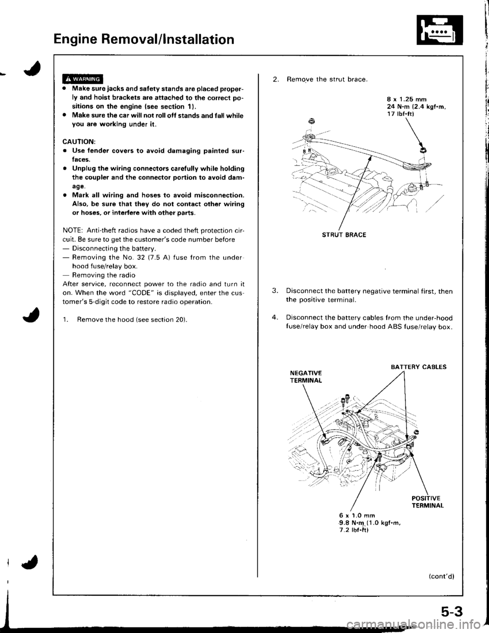
2. Remove the strut brace.
Make sure iacks and safety stands ate placed plopel-
ly and hoist brackets are attached to the correct po-
sitions on the engine {see section 11,
Make sure the car will not rollolt stands and latl whileyou are wgrking under it.
8 x 1.25 mm24 N.m {2.4 kgf.m,17 tbf.tt)
CAUTION:
. Use fender covers to avoid damaging painted sur-
faces.
Unplug the wiring connectors carelully while holding
the coupler and the connector portion to avoid d8m-
age.
Mark all wiring and hoses to avoid misconnection.
Also. be sure that they do not contact other wiring
or hoses, or intedere with other parts.
NOTE: Anti-theft radios have a coded theft protection cir-
cuit. Be sure to get the customer's code number betore- Disconnecting the battery.- Removing the No.32 (7.5 A) fuse from the under
hood fuse/relay box.
Removing the radio
After service, reconnect power to the radio and turn it
on. When the word "CODE" is displayed, enter the cus
tomer's 5-digit code to restore radio operation.
1. Remove the hood (see section 20).
3.Disconnect the battery negative terminal first, then
the positive terminal.
Disconnect the battery cables Irom the under-hood
Iuse/relay box and under hood ABS {use/relay box.
6x1.0mm9.8 N.'4 (1 .0 kgf .m,
7.2 rbf.ft)
(cont'dl
STRUT BRACE
BAITERY CABLES
5-3
Page 48 of 1681
Engine Ramoval/lnstallation
(cont'dl
13. Remove the engine wire harness connectors, termi-
nal and clamps on the left side ot engine compan-
menr,
6 x 1.0 mm9.8 N.m 11.0 kgl.m,7.2 tbt.ttl
14. Remove the cruise control actuator.
I x 1.25 mm24 N.m 12.4 kgt.m,17 tbt.ft)
5-6
A/C COMPRESSOR EELT
\
l.15.
to.
Remove the engine ground cable at the body end.
Remove the adjusting bolt and mounting bolts, then
remove the power steering (P/S) pump belt and
pump.
. Do not disconnect the P/S hoses.
MOUNTING BOLTSI x 1.25 mm24 N.m 12.4 kgt'm, 17 lbl.ft)
Loosen the idler pulley bolt and adjusting bolt, then
remove the air conditioning (Ay'C) compressor belt.
IDLER PULLEY BOLT10 x 1.25 mm/14 N'm 14.5 kgf.m, 33 lbt'frl
I
I
't7.
Page 51 of 1681
7
30.Disconnect the primary heated oxygen sensor(Primary HO2S) connector, then remove exhaust
pipe A.
818C1 engine:PRIMARYHO2S
8 x 1.25 mm24 N.m 12.4 kgl.m.t7 rbt.fttReplace.
GASKETReplace.
Replace.
SELF-LOCKING I{UT8 r 1.25 mm16 N.m (1 .6 kgf .m,
12 tbt.frtBeplace.
EXHAUSTPIPE A
NUT10 x 1.25 mm54 N.m {5.5 kgt'.n, tlo lbt.ft}Replace.
81881, 818C5 engines:
PRIMARYHO25 CONNECTOF
GASKETReplace.
GASKETReplace.
S€LF.LOCKING NUT
8 x 1.25 mm16 N.m (1.6 kgf'm,12 tbt.fr)Replace.f{UT10 x 1.25 mm54 N.m {5.5 kgf'm,40 lbf.ftlReplace.
8 x 1.25 mm24 N.m (2.4 kgt.m,17 lbf.frlReplace.
31. Remove the shift rod and extension rod {Mff).
8 x 1.25 mm22 N'm 12.2 kgl.m, '16 lbt.ttl
32. Remove the shift cable (A,/T).
I x 1.25 mm22 N-l'. 12.2 kgl.m,16 lbf.frl
SHIFT CABLE
CONTROLLEVER
6 x 'l.O mm14 N.m {1.4 kgf.m, 10 lbt.ft}
SHIFT ROD
RETAINER
SHIFT CABLE
LOCK WASHER
{cont'd)
COVER
5-9
Page 58 of 1681

Engine Removal/lnstallation
{cont'dl
7. Install the left front mount, then tighten the bolts in
the numbered sequence shown (O - @).
O t2 x '1.25 mm83 N.m 18.5 kgt.m,61 lbl.ft)Fleplace.
@ 12 x 1.25 mm59 N.m 16.0 kgf.m,43 lbf.frlReplace.
O 10 x 1.25 mmil4 N.m 14.5 kgt'm,33 lbt.ft)
,5-16
. Check that the spring clip on the end of each
driveshaft clicks into place.
CAUTION: Use new spring clips.
. Bleed air {rom the cooling system at the heater
valve open (see page 10-6).
. Adjust the throttle cable (see section 1 1).
. Check the clutch pedalfree play (see section 12).
. Check that the transmission shifts into gear
smoothlY.
. Adjust the tension of the following drive belts.
Alternator belt {see section 23).
P/S pump belt (see section 171.
A/C comDressor belt (see section 22).
! Inspect for tuel leakage (see section 1ll.. After assembling fuel line parts, turn on the
ignition switch (do not operate the staner) so
that the fuel pump operates for approximately
two seconds and the fuel line pressurizes.
Repeat this operation two or three times and
check for tuel leakage at any point in the {uel
line.
Page 80 of 1681
Gylinder Head
Removal (cont'dl
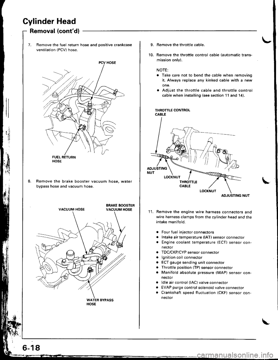
Remove the fuel return hose and positive crankcase
ventilation (PCV) hose.
Remove the brake booster vacuum hose, water
bypass hose and vacuum hose.
ltosE
VACUUM HOSE
6-18
10.
9.
11.
Remove the throttle cable,
Remove the throttle control cable (automatic trans-
mission only).
NOTE:
. Take care not to bend the cable when removing
it. Always replace any kinked cable with a new
one.
. Adjust the throttle cable and throttle control
cable when installing (s€e section 11 and 14).
THROTTLE CONTROLCABLE
ADJUSTING NUT
Remove the engine wire harness connectors and
wire harness clamps f.om the cylinder head and the
intake manifold.
Four fuel injector connectors
Intake air temperature (lATl sensor connector
Engine coolant temperature {ECT) sensor con,
nector
TDC/CKP/CYP sensor connector
lgnition coil connector
ECT gauge sending unit connector
Throttle position (TP) sensor connector
Manifold absolute pressure (MAP) sensor con-
necto r
ldle air control (lAC) valve connector
EVAP purge control solenoid valve connector
Crankshaft speed fluctuation (CKF) sensor con-
nector
a
a
a
a
a
a
a
a
ADJUSTING
Page 211 of 1681
Gomponent Locations
Index (cont'dl
THROTTLE BODY {TBIInspection, page 1 1'132
Disassembly, page 1 1-133
THEOTTLE CABLEInspection/Adjustment, pages 11-130, 131
lnstallation, Pages 11 130' 131AIR CLEANER IACL)Replacement, Page 11 129
RESONATOR
INTAKEAIRBYPASS {IAB)CONTROLDIAPHRAGM(818C1 engine onlylTroubleshooting,page 11-135
i-)
i--- / /
i rl
l'-' i
INTAIR
POSITIVE CRANKCASEVENTILATION (PCV) VALVEInspection, page 11'140
BYPASS IIAB}CONTROLSOLENOIDVALVE (818C1 ongine only)
Troubleshootrng,page 11-135
PGM-FIMAIN RELAYRelayTesting, Page 11 124
Troubleshooting, Page 1 1-1 25
L
ENGINE CONTROL MODULE IECM}
Tro!bleshooting, Page 11 50
SERVICE CHECK CONNECTOR {2P)
Troubleshooting Procedures, page 1 1'32
DATA LINK
1 1-6
\'
Page 241 of 1681
Troubleshooting
Troubleshooting Procedures (cont'd)
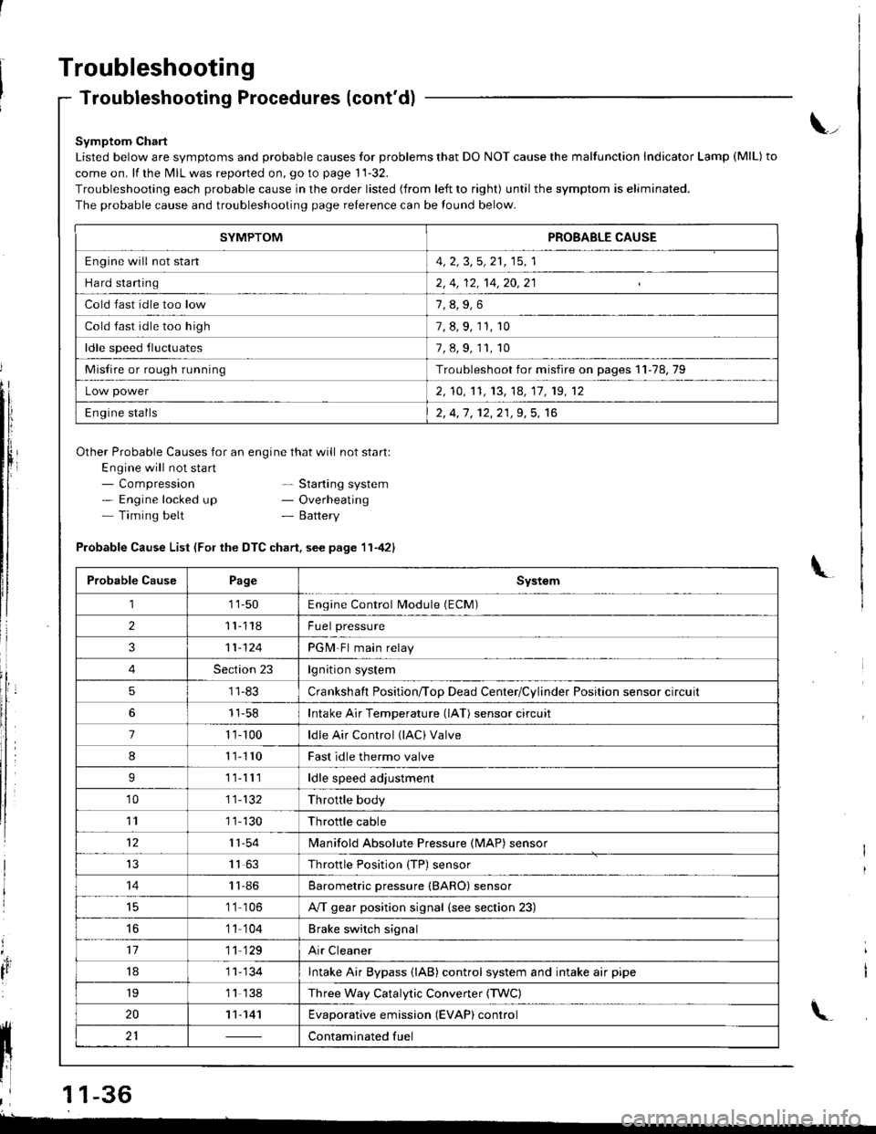
Symptom Chart
Listed below are symptoms and probable causes for problems that DO NOT cause the malfunction Indicator Lamp (MlL) to
come on. lf the MIL was reported on, go to page 11-32.
Troubleshooting each probable cause in the order listed (from left to right) until the symptom is eliminated.
The probable cause and troubleshooting page relerence can be found below.
Other Probable Causes for an engine that will not start:
Engine will not sta rt- Compression- Engine locked up- Timing belt
\_
- Starting system- Overheating- Battery
'4,
It
Probable Cause List (For the DTC chart. see page 11-421
Probable CausePageSystem
111-50Engine Control Module (ECM)
211118Fuel pressure
311-124PGM-Fl main relay
4Section 23lgnition system
51 1-83Crankshaft Position/ToD Dead Center/Cylinder Position sensor circuit
11-58Intake Air Temperature (lAT) sensor circuit
71 't- 100ldle Air Control (lAC) Valve
811110Fast idle thermo valve
I11lllldle speed adjustment
'1011-132Throttle body
111 1-130Throttle cable
1211-54lvlanifold Absolute Pressure {MAP) sensor
IJ1163Throttle Position {TP) sensor
1411-86Barometric pressure (BARO) sensor
1 '1 106A/T gear position signal {see section 23)
16'1 1 104Brake switch signal
1711 129Air Cleaner
181 1- 134Intake Air Bypass {lAB} control system and intake air pipe
19'1 1 138Three Way Catalytic Convener (TWC)
2011-141Evaporative emission (EVAP) control
21Contaminated fuelll ll 21 | - | cont"-in"t"o tu"
11 l-
I
,l 11-36
-
SYMPTOMPROBABLE CAUSE
Engine will not stan4, 2, 3,5, 21, 15, 1
Hard starting2, 4, 12, 14,20,21
Cold fast idle too low
Cold fast idle too high7, 8, 9, 11, r0
ldle speed fluctuates7,8,9,11,10
Misfire or rough runningTroubleshoot for misfire on pages 11-78,79
Low power2, 10,'t1, 13, 14, 17, 19, 12
Engine stalls2, 4,1 , 12,21,9, 5, 16


