1998 HONDA INTEGRA power steering
[x] Cancel search: power steeringPage 1048 of 1681
Compressor
Replacement
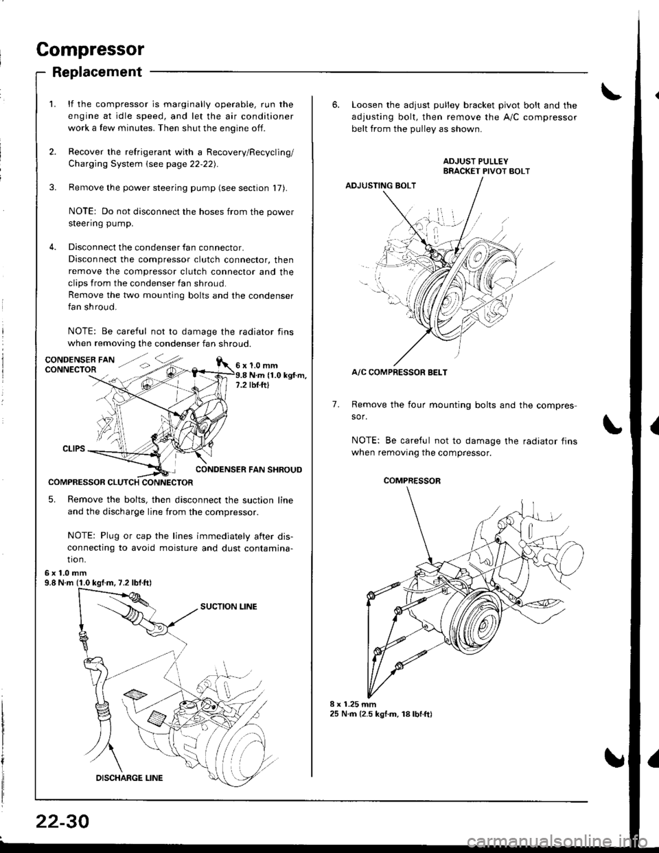
lf the compressor is marginally operable, run the
engine at idle speed, and let the air conditioner
work a few minutes. Then shut the engine off.
Recover the refrigerant with a Recovery/Recycling/
Charging System \see page 22-22).
Remove the power steering pump (see section 17).
NOTE: Do not disconnect the hoses from the power
steering pump.
Disconnect the condenser fan connector.
Disconnect the compressor clutch connector, then
remove the compressor clutch connector and the
clips from the condenser fan shroud
Remove the two mounting bolts and the condenser
fan shroud.
NOTE: Be careful not to damage the radiator fins
when removing the condenser fan shroud.
1.0 mmN.m (1.0 kgt.m,rbf.ftt
CONDENSER FAN SHROUD
COMPRESSOR CLUTCH CONNECTOR
5. Remove the bolts, then disconnect the suction line
and the discharge line from the compressor.
NOTE: Plug or cap the lines immediately aiter dis-
connecting to avoid moisture and dust contamina-
tio n.
6x1.0mm9.8 N.m (1.0 kgf.m, 7.2 lbf.ft)
22-30
6. Loosen the adjusl pulley bracket pivot bolt and the
adjusting bolt, then remove the A/C compressor
belt from the Dullev as shown.
ADJUSTING BOLT
A/C COMPRESSOR BELT
Remove the four mounting bolts and the compres-
sor.
NOTE: Be careful not to damage the radiator fins
when removing the compressor.
7.
./.,
COMPRESSOR
Page 1049 of 1681
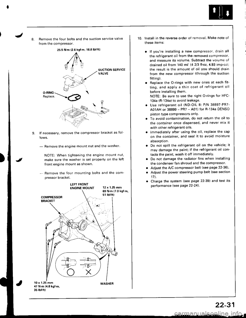
J8. Remove the four bolts and the suction servtce valve
from the compressor.
25.s18.8 tbf.ft)N.m {2.6 kgt.m,
A\
-/ l=\'zI
i:-
9.
SUCTION SERVICEVALVE
O-RING \Benrace. --'.l4p
lf necessary, remove the compressor bracket as fol
- Remove the engine mount nut and the washer'
NOTE: When tightening the engane mount nut,
make sure the washer is set properly on the left
front engine mount as shown.
- Remove the four mounting bolts and the com-
pressor bracket.
LEFT FRONTENGTNE MOUNT 12 x 1.25 mm
I
69 N.m {7.0 kg{.m.s1 rbt.ft)
10 x 1.25 mm47 N.m (4.8 kgf.m.35 rbf.ftt
10. lnstall in the reverse order of removal. Make note of
these rtems:
) lf you're installing a new compressor, drain all
the refrigerant oil from the removed compressor,
and measure its volume, Subtract the volume of
drained oil from 140 m{ 14 2/3ll.oz,4.93 imp.oz);
the result is the amount of oil you should drain
from the new compressor (through the suction
{itting).
r Replace the O-rings with new ones at each fit-
ting, and apply a thin coat of refrigerant oil
before installing them.
NOTE: Be sure to use the right O-rings for HFC-'t34a (R-134a) to avoid leakage.
. use refrigerant oil (ND-OlL 8: P/N 38897 PR7-
A0IAH or 38899 - PR7 - A01) for R-'134a DENSO
piston type compressors onlY.
. To avoid contamination, do not return the oil to
the container once dispensed, and never mix it
with other refrigerant oils.
. lmmediately after using the oil, replace the cap
on the container, and seal it to avoid moisture
aDsorDt|on.
. Do not spill the refrigerant oil on the vehicle; it
may damage the paint; if the refrigerant oil con-
tacts the Daint, wash it off immediately.
. Do not damage the radiator fins when installing
the condenser fan shroud and the compressor.
. Adjust the Ay'C compressoi belt {see page 22-36J
. Adjust the power steering pump belt (see section
17J.
. Charge the system (see page 22-39) and test its
performance {see Page 22-24).
WASHER
22-31
Page 1054 of 1681
A/C Compressor Belt
Adiustment
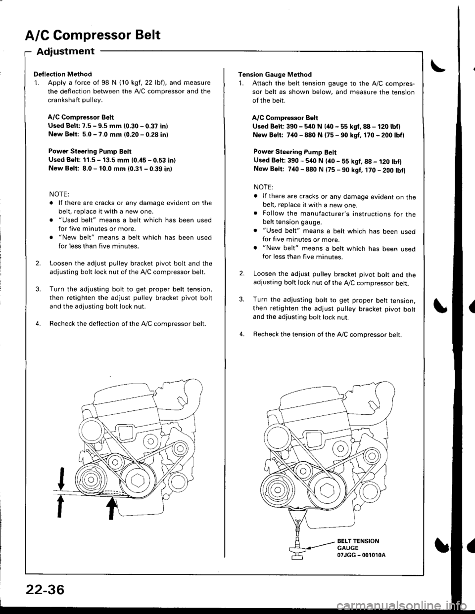
Dellection Method
1. Apply a force of 98 N i10 kgf, 22 lbf), and measure
the deflection between the A,/C compressor and the
crankshaft pullev.
A/C Compressor Belt
Used Belt: 7.5 - 9.5 mm (0.30 - 0.37 in)
New Beli: 5.0 - 7.0 mm (0.20 - 0.28 in)
Power Steering Pump Belt
Used Bslt: 11.5 - 13.5 mm (0.i15 - 0.53 in)
New Belt: 8.0 - 10.0 mm (0.31 - 0.39 in)
NOTE:
. lf there are cracks or any damage evident on the
belt, replace it with a new one.
. "Used belt" means a belt which has been used
for five minutes or more.
. "New belt" means a belt which has been used
for less than five minutes.
Loosen the adjust pulley bracket pivot bolt and the
adjusting bolt lock nut of the lVC compressor belt.
Turn the adjusting bolt to get proper belt tension,
then retighten the adjust pulley bracket pivot bolt
and the adjusting bolt lock nut.
Recheck the deflection of the Ay'C compressor belt.
22-36
Tension Gauge Method
1. Attach the belt tension gauge to the Ay'C compres-
sor belt as shown below, and measure the tension
of the belt.
A/C Comprossor Belt
Used Belt: 390 - 5/rc N (4O - 55 kgf. 88 - 120 lbf)
New Bslt: 7,10 - 880 N (75 - 90 kgf, 170 - 200 lbf)
Power Steering Pump Belt
Used Belt: 390 - 540 N (ito - 55 kgl, g8 - i20 tbtlNew Belt: 740 - 880 N (75 - 90 kgt, 170 - 200 tbtl
NOTE:
. lf there are cracks or any damage evident on thebelt, replace it with a new one.. Follow the manufacturer's instructions for thebelt tension gauge.
. "Used belt" means a belt which has been usedfor five minutes or more.. "New belt" means a belt which has been usedfor less than five minutes.
Loosen the adjust pulley bracket pivot bolt and theadjusting bolt lock nut of the A,/C compressor belt.
Turn the adjusting bolt to get proper belt tension,then retighten the adjust pulley bracket pivot boltand the adjusting bolt lock nut.
Recheck the tension of the A,/C compressor belt.
3.
BELT TENSIONGAUGE07JGG - 0010'l0a
Page 1077 of 1681
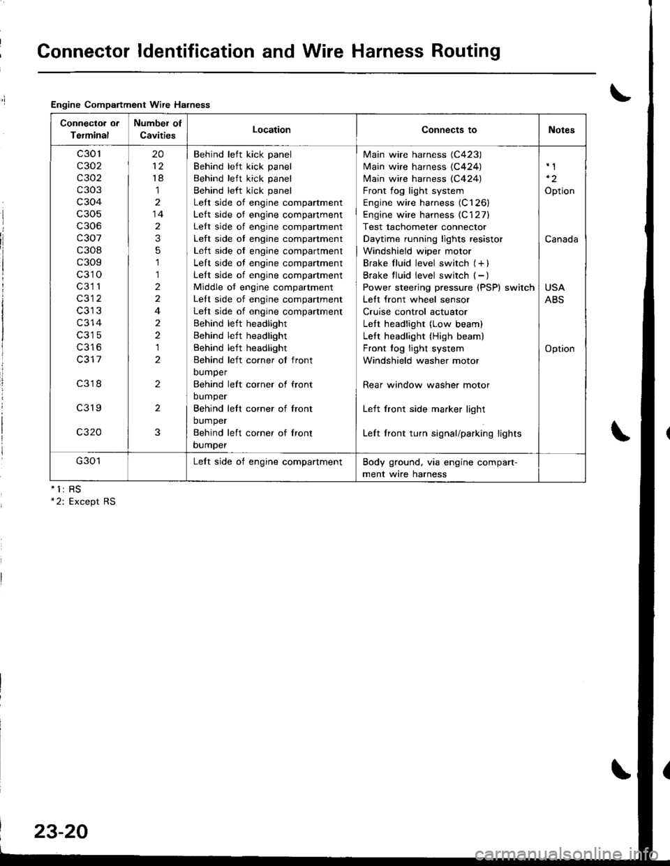
Connector ldentification and Wire Harness Routing
Engine Compartment Wire Halness
nll
Connectoa ot
Terminal
Number of
CavitiesLocationConnects toNotes
c301
c302
c 302
c303
c304
c306
c307
c308
c309
c310
c3l 1
c312
c314
c316
c317
c318
c319
c320
20
't8
1
14
2
3
5
1
1
2
2
4
2
2
1
2
2
2
3
Behind left kick panel
Behind left kick panel
Behind left kick panel
Behind left kick panel
Lett side of engine compartment
Lett side of engine companment
Lett side of engine compartment
Left side of engine compartment
Left side of engine compartment
Left side of engine compartment
Left side of engine compartment
Middle of engine compartment
Lett side of engine companment
Left side of engine compartment
Behind left headlight
Behind left headlight
Behind left headlight
Behind left corner of front
DUmper
Behind left corner ol front
bumper
Behind lett corner of front
bumper
Behind left co.ner of lront
bumper
Main wire harness (C423)
Main wire harness {C424)
N4ain wire harness (C424)
Front fog light system
Engine wire harness (C126)
Engine wire harness (C'127)
Test tachometer connector
Daytime running lights resistor
Windshield wiper motor
Brake f luid level switch (+ )
Brake f luid level switch ( - )
Power steering pressure (PSP) switch
Lett front wheel sensor
Cruise control actuator
LeIt headlight (Low beam)
Lett headlight {High beam)
Front fog light system
Windshield washer motor
Rear window washer motor
Left front side marker light
Left front turn signal/parking lights
Option
Canada
USA
ABS
Option
G301Lelt side of engine compartmentBody ground, via engine compart-
ment wire harness
23-20
Page 1130 of 1681
;
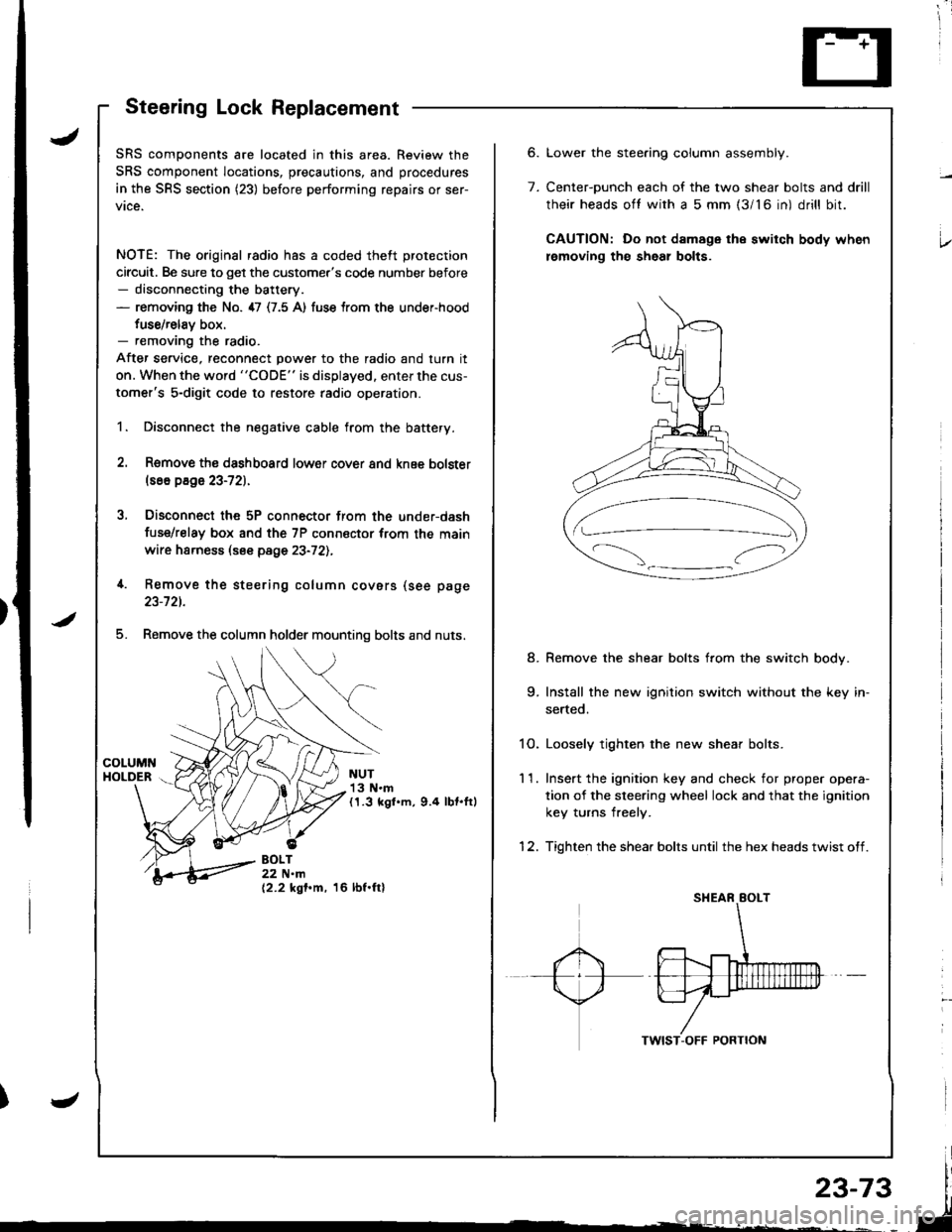
Steering Lock Replacement
SRS components are located in this area. Review the
SRS component locations, precautions, and procedures
in the SRS section (23) before performing repairs or ser-
vice.
NOTE: The original radio has a coded theft protection
circuit. Be sure to get the customer's code number before- disconnecting the battery.- removing the No. 47 (7.5 A) fuse trom the under-hood
fuse/relav box.- removing the radio.
After service, reconnect power to the radio and turn it
on. When the word "CODE" is displayed. enter the cus-
tomer's 5-digit code to restore radio operation.
1. Disconnect the negative cable from the battery.
2. Remove ths dsshboard lower cover and knee bolster(s6o p8ge 23-72).
3, Disconnect the 5P connector from the under-dash
fuse/relay box and the 7P connsctor from th€ main
wire harness (see page 23-72l.,
4. Remove the steering column covars (see page
23-721.
5. Remove the column holder mounting bolts and nuts.
NUT13 N.m(1.3 kgl.m, 9.4 lbt.ftl
BOLT22 N.m(2.2 kgf.m, 16 lbf.ftl
6.
7.
Lower the stee.ing column assembly.
Center-ounch each of the two shear bolts and drill
their heads oft with a 5 mm {3/16 in) drill bit.
CAUTION: Do not damage the switch body when
lemoving th€ sheal bolts.
Remove the shear bolts from the switch body.
Install the new ignition switch without the key in-
serted.
1O. Loosely tighten the new shear bolts.
11. Ins€rt the ignition key and check for proper opera-
tion of the sleering wheel lock and that the ignition
key turns freely.
12. Tighten the shear bolts until the hex heads twist off.
8.
Page 1225 of 1681
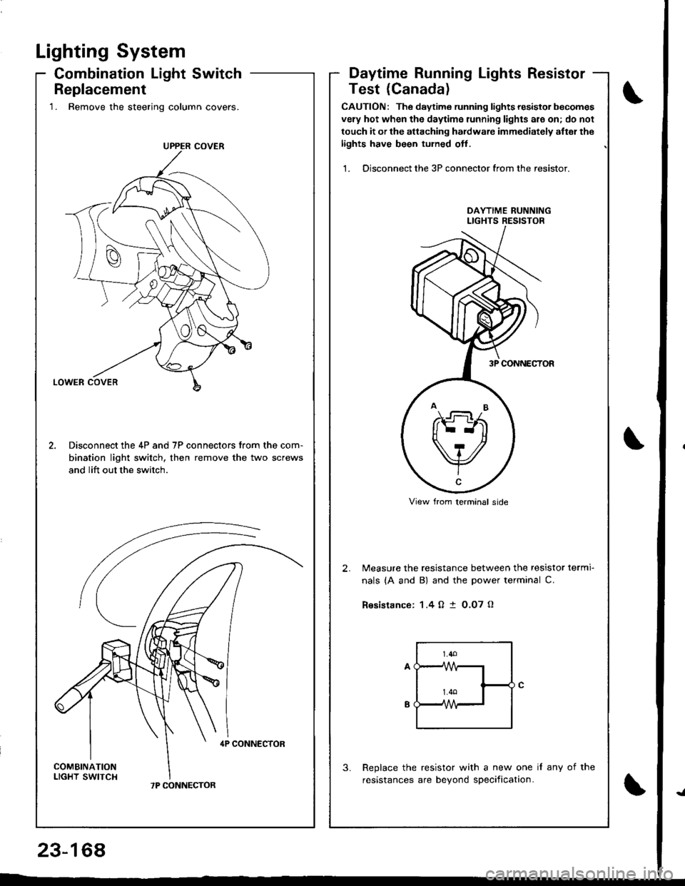
Replacement'1. Remove the steering column covers.
Disconnect the 4P and 7P connectors from the com-
bination light switch, then remove the two screws
and lift out the switch.
,P CONNECTOR
Lighting System
Combination Light SwitchDaytime Running Lights Resistor
Test (Canada)
CAUTION: The daytime running lights resistor becomes
vely hot when the daytime running lights arc on; do not
touch it or the attaching hardware immediately altel the
lights have been tulned otf.
1. Disconnect the 3P connector from the resistor.
DAYTIME RUNNINGLIGHTS RESISTOR
2.Measure the resistance between the resistor termi-
nals (A and B) and the power terminal C.
Resistance: 1.4 O 1 O.O7 o
Replace the resistor with a new one il any of the
resistances are beyond specification.
;w;
V
View from terminal side
23-168
Page 1406 of 1681
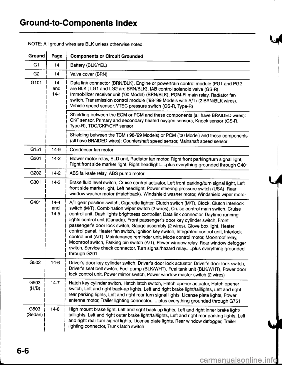
Ground-to-Components I ndex
NOTE: All ground wires are BLK unless otherwise noted.
GroundPageComponents or Circuit Grounded
Battery (BLIVYEL)
--t'I Valve cover (BRN)
G101t.+
and
14-1
Daia link connector (BRN/BLK), Engine or powertrain controt module (pct and pG2
are BLK; LG1 and LG2 are BRN/BLR, IAB controt solenoid valve (GS-B),
lmmobilizer receiver unit ('00 Model) (BRN/BLR, PGM-Ft main retay, Radiator fan
switch, Transmission control module ('98.�99 Models with MD (2 BRN/BLK wires),
Vehicle speed sensor, WEC pressure switch (GS-R, Type-R)
Shielding between the ECM or PCM and these components (all have BRAIDED wires):
CKF sensor, Primary and secondary heated oxygen sensors, Knock sensor (GS-R,
Type-R), TDC/CKP/CYP sensor
Shielding between the TCM ('98-'99 Models) or PCM ('00 Model) and these components(all have BRAIDED wires): Countershaft speed sensor, Mainshaft speed sensor
G1s1 ii Condenser fan motor
Brake fluid level switch, Cruise control actuator, Left front parking/turn signal light, Left
front side marker light, Left headlight, Power steering pressure switch (USA), Rear
window washer motor (Hatchback), Windshield washer motor, Windshield wiper motor
14-3
Blower motor relay, ELD unit, Badiator fan motor, Right front parking/turn signal light,
Right front side marker light, Right headlight.....plus everything grounded through G401
ABS fail-safe relay, ABS pump motor
G40114-4
ano
l4-c
A,/T gear position switch, Cigarette lighter, Clutch switch (M,/T), Ctock, Ctutch interlock
switch (MfD, Combination wiper switch (2 wires), Cruise control main switch, Cruise
control unit, Dash lights brightness controller, Data link connector, Daytime running
lights control unit (Canada), Front passenger's door key cylinder switch, Frontpassenger's door lock switch, Gauge assembly (2 wires), Glove box light, Heater
control panel, Heater tan switch, lgnition key switch, Integrated control unit, Interlock
control unit (AfI), Maintenance reminder unit, Mode control motor, Moonroof relay,
Moonroof switch, Parking pin switch (AfD, Power window relay, Rear window defogger
switch, Service check connector, Turn signal/hazard relay.....plus everything grounded
throuoh G201
Driver's door key cylinder switch, Driver's door lock actuator, Drivels door lock switch,Driver's seat belt switch, Fuel pump (BLI(/WHT), Fuel tank unit (BLI(/WHT), power doorlock control unit, Power mirror switch, Power window master switch (2 wires)
Hatch key cylinder switch, Hatch latch switch, Hatch opener actuator, Hatch ooener
switch, Left and right back-up lights, Left and right brake light/taillights, Lett and right
rear parking lights, Left and right rear turn signal lights, License plate lights, power
antenna motor, Trailer lighting connector..... plus everything grounded through G751
6-6
'14-8G503
(Sedan)
High mount brake light, Left and right back-up lights, Lett and right inner brake tighv
taillights, Left and right outer brake light/taittights, Left and right rear parking tights, Leftand right rear turn signal lights, License plate lights, Rear window detogger, Trailer
lighting connector, Trunk latch switch
Page 1409 of 1681
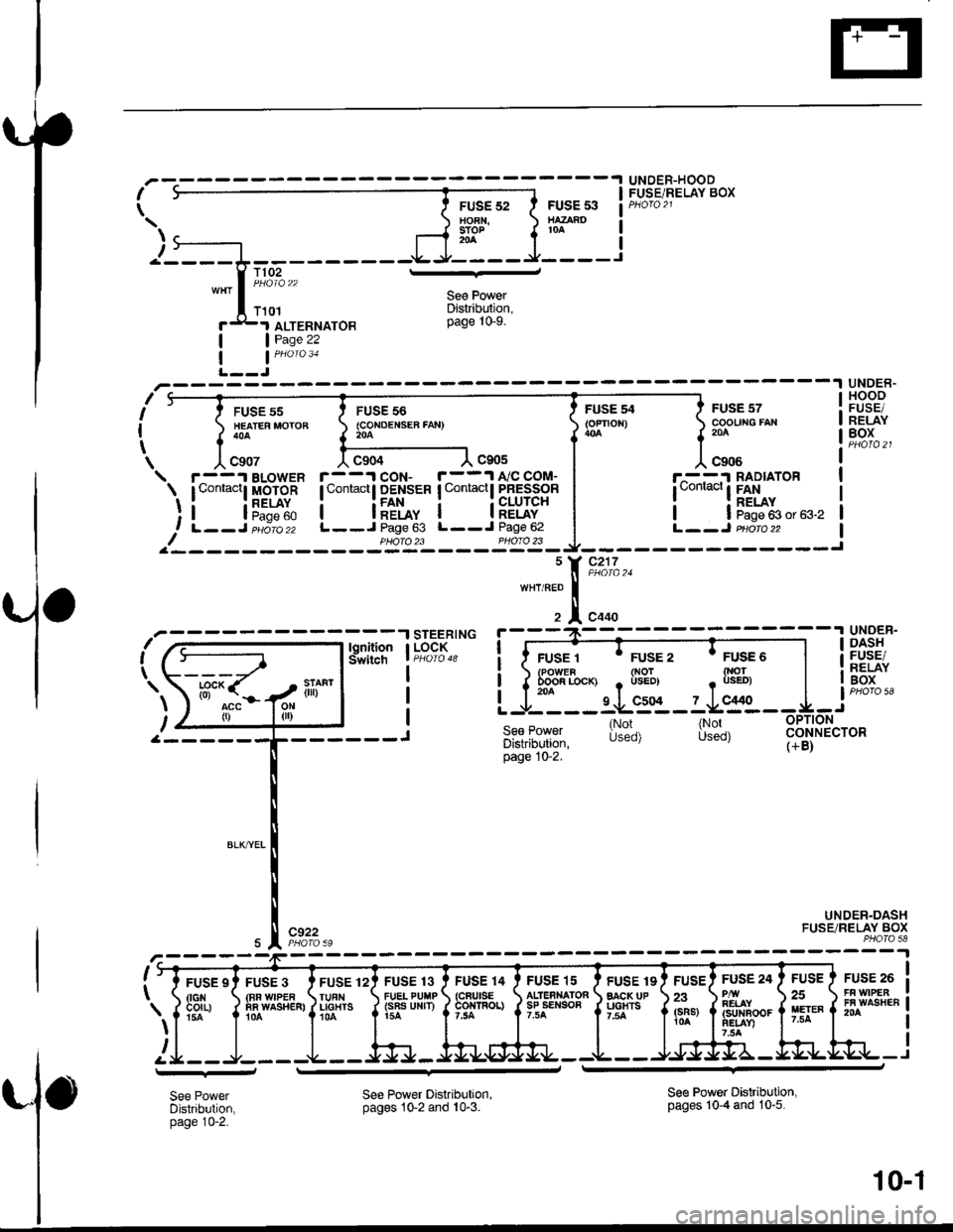
I
I
I
IJ
UNDER-HOODFUSE/RELAY BOXI
\
\.t)-
FUSE 528OFN,STOP
FUSE 53HAZARO
I'_'I ALTERNATOB
See PowerDistribution,page 10-9.
| | Pase 22
| | PHoro 31
L--J
1102
T101
FUSE 55HEATEF MOTOB
UNDEB.HOOOFUSE/RELAYBOX
FUSE 56(CoNDENSEA FAtl)204
c904
FUSE 13FUELPUTiP(sB6 UNrr)
I
I
tc907
r--'t BLowER\. tContactl MO-IOR
!ilF"'s?60RELAYI rdq€ @I L--J eudro zz
FUSE 54{oFnon)
."-'1tr;'
FUSE 57COOUNG FAX204
c9)6
r^- -:I RADIATOR
!"o"'""' ! Etto"! | Page 63 or 63.2L--J Pqofo ?2
c90s
r--1coN- r--1A'/CCOM-I Contactl DENSER I Contactl PRESSOR
! IFAN : ; CLUTCNI I RELAY I I RELAYL - - J Page 63 L--J Page 62
-- - -'l UNOER-i-
i I ruser ' rusez 'rusEo I if99Ff.
i ) &*'s"-, ,lil?l, , $?'"r I ii,At:
L -J- --- lLg%- ? J..9Yl--:1,- j
se€ Power l[:'^. l[:'^, 3!I$f"totDiskibution. ubEu/ uJcv / (+B)page 10-2.
c922
UNDER.DASHFUSE/RELAY BOXPHOfa 58
,rar ra !t#
i t FUSE st FusE 3I dcr{ rFRwtPE {tG
nn WIPEF
fis., fllo"o.".",
I
FUSE 12TUfNLIGTITSr0A
FUSE 'I5
ALlERNATOf,sP sENSoa7.tA
FUSE 19BACK UPUGHTSt.5a
FUSE 24
REIAY€rrNBooFNEIAY)?.3A
FUSE
25II€TEF7.5A
FF WPEBFA U'ASHEN204
4y--J---J
.l STEERINGI LOCK
I
I
I
J
! -l tanfiton,. ( t--) lsiwitctr
".r\l:'S7ili"'l
lf 0 ltttt I
a------rl-
l;9c* ('-' oa"t0)
--
See PowerDistribution,page 10-2.
See Power Distribution,pages 10-2 and 10-3.See Power Distribution,pages 10-4 and 10"5.
10-1