Page 1194 of 1681

t
{)
)
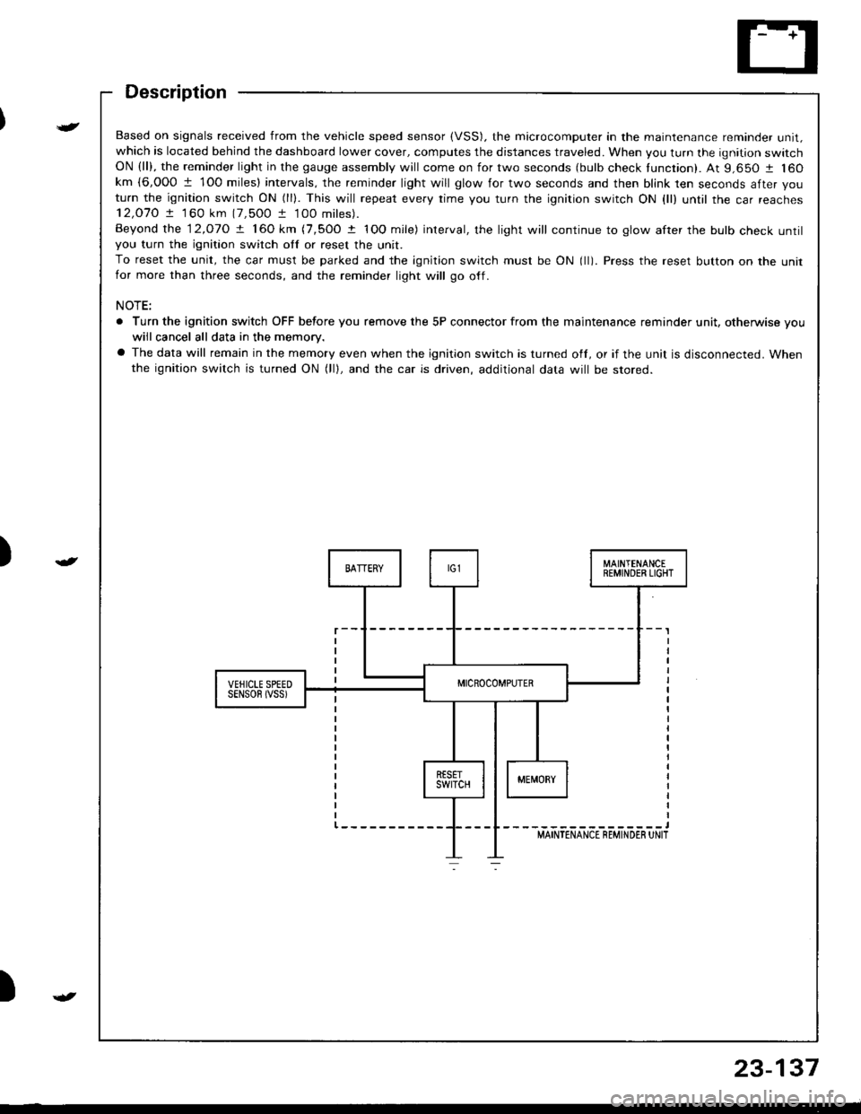
Based on signals received from the vehicle speed sensor (VSS). the microcomputer in the maintenance reminder unit,which is located behind the dashboard lower cover, computes the distances traveled. When you turn the ignition switchON (ll), the reminder light in the gauge assembly will come on for two seconds (bulb check tunction). At 9,650 1 160km {6,000 1 1O0 miles} intervals, the reminder light will glow for two seconds and then blink ten seconds after you
turn the ignition switch ON (ll). This will repeat every rime you turn the ignition switch ON {ll) until rhe car reaches12,O7O ! 1 60 km (7,500 t 100 miles).
Beyond the 12.o1O ! 160 km (7,5OO t IOO mile) interval, the light will continue to glow after the bulb check untilyou turn the ignition switch otf or reset the unit.
To reset the unit, the car must be parked and the ignition switch must be ON (ll). Press the reset button on the unitfor more than three seconds, and the reminder light will go off.
NOTE:
. Turn the ignition switch OFF before you remove the 5P connector from the maintenance reminder unit, otherwise vouwiil cancel all data in the memory.
a The data will remain in the memory even when the ignition switch is turned off, or if the unit is disconnected. Whenthe ignition switch is turned ON (lll, and the car is driven, additional data will be stored.
{
23-137
Page 1342 of 1681

v
-t f--.l r --1 f-M.in cod. {11 S!b{od. (2}
oTcr2
-l F --{ FMain cod. (l) Sub-cod.11).--.Y-oTc r-rThnd'm6r.@6m
2
ON
light sl.ys on h ct36 or
Troubleshooting
Reading the DTC (cont'd)
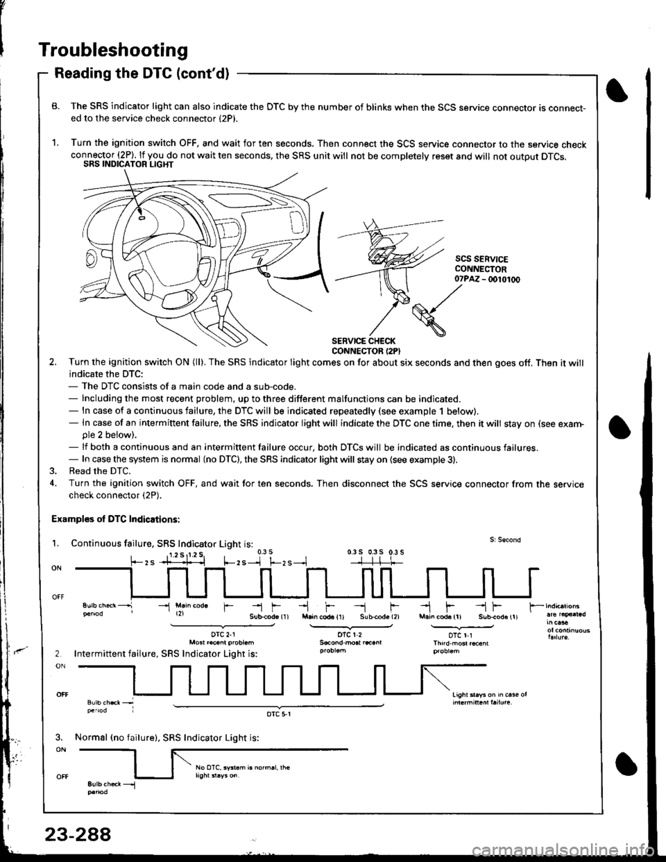
B. The SRS indicator light can also indicate the OTC by the number of blinks when the SCS service connector ts connect-ed to the service check connector (2P).
1. Turn the ignition switch OFF, and wait for ten seconds. Then connect the SCS service connector to the service checkconnector (2P). lf you do not wait ten seconds, the SRS unit will not be completelv reset and will not outout DTCS.SRS INDICATOR LIGHT
scs SERV|CECONI{ECTOR- (x)l01(x)
SERVICE CHECKCONNECTOR (2PI
2. Turn the ignition swilch ON (ll). The SRS indicator light comes on for about six seconds and then goes off. Then it will
indicate the DTC:- The DTC consists of a main code and a sub-code.- Including the most recent problem, up to three different malfunctions can be indicated.- ln case of a continuous failure, the DTC will be indicated repeatedly (see example 1 below).- In case of an intermiftent failure, the SRS indicator light will indicate the DTC one time. then it will stay on (see exarn-ple 2 beiow).- lf both a continuous and an intermittent failure occur, both DTCS will be indicated as continuous failures.- In case the system is normal (no DTC), the SRS indicator light will stay on {see example 3).
3. Read the DTC.
4. Turn the ignition switch OFF, and wait for ten seconds. Then disconnect the SCS service connector from the servicecheck connector (2P),
Examples ol DTC Indications:
L Continuous failure, SRS Indicator Light is:0.3 s 0.3s 0.3 s-]-]-l-t-
07?M
(S./'
\
-l Mlin cod. r
orc 2-1Mo3t r.cant probt.m
Intermittent failure, SRS Indicator Light is:
Normsl (no failure), SRS Indicator Light is:
oTc 5,r
Page 1373 of 1681
I
I
6. Reconnect the airbag connector(s).
Front Passenger's Side:
. Attach the airbag connector to the connector holder.
then reinstallthe glove box.
CONNECTOR HOLDER
Driver's Side:
. Connect the driver's airbag 2P connector to the cable
reel 2P connector, then rnstall the access panel on the
steering wheel.
\,
23-319
7.Connect the baftery positive cable, then connect thenegative cable.
After installing the airbag, confirm proper system
operal|on:
. Turn the ignition switch ON (ll); the SRS indica-
tor light should come on for about six seconds
and then go off.
. Make sure both horn buttons work.
. Take a test drive, and make sure the cruise con-
trol switches work.
Enter the anti-theft code for the radio. then enter the
customer's radio station presets,
9.
Page 1379 of 1681
Instsll the steering wheel bolt, then install the driv-
er's airbag.
TORX BOLTS9.8 N m {1.0 kgf'm,7.2 lbtftlReplace.U3e . Torx T30 bit.
STEERING WHEEL NUT19 N.m (5 kgl.m, 36 lbl.ftl
Anach the 2P and 3P connectors to the connector
holder. then install the knee bolster and dashboard
lowgr cover,
le
CONNECTOR HOLDER
DASHBOARD LOWER COVER
23-325
\
'19. Reconnect the driver's aibag 2P connector to the
cable reel 2P connector, and reinstSll the access
panel on the steering wheel.
20, Reconnect the battery positive cable, then the nega-
tivs cable.
21. After installing the cable reel, confirm proper sys-
tgm operation:
Turn the ignition switch ON (ll); the SRS indica-
tor light should come on for about six seconds
and thsn go off.
Make surs both horn buttons work.
Make sure the headlight and wiper switches
Go {or a test drive, and make sure the cruise con-
trol switches work.
Ent6r the anti-theft code for tho radio, then enter the
customsr's radio station presets.
a
a
Page 1502 of 1681

How the Circuit Works
The maintenance reminder light comes on to
remind the driver that the car is due for
scheduled mainlenance.
The maintenance reminder unit receives a vehicle
speed input from the vehicle speed sensor (VSS)
and uses this inlormation to compute the distance
traveled. For the first 6000 t 1 00 miles (9650 t 160
km) after the maintenance reminder light is reset, it
will come on for two seconds when you turn the
ignition switch to ON (ll) as a bulb check.
Between 6000 1 100 miles (9650 t 160 km) and
7500 t 100 miles (12070 I 160 km) the reminder
light will come on for two seconds when you turn
the ignition switch to ON (ll), and then flash for eight
seconds more.
Beyond 7500 t 100 miles (12070 t l60 km) the
reminder light will stay on when the ignition switch is
in the ON (ll) position until the unit is reset.
To reset the unit, the car must be parked and the
ignition switch in the ON (ll) position. Press the
reset button on the unit and hold it there for more
than three seconds, and the reminder light will
go off.
Refer to the Service Manual (Section 23, Electrical)
for specific tests or troubleshooting procedures.
83-1
Page 1537 of 1681
- Front Passenger's Door (Sedan)
From B onracrng page.
UNDER.DASHFUSE/RELAYBOXPHOIA 5A
Motor has a self-resettingcircuit breaker.
_______s_1, C632
u,-r'o"* |
9,t::""" I
1ffil$r'.'NJT
-------J.ont
FRONTPASSENGER'SwtNDowswtTcH
POWERwtNDowMASTERSWITCH
BLU/WHT
BLU/WHT
;;",;1"c"x%-rg .l cazr
;=r"X":
17
BLU/YEL
10
",-u o";f tbb ^
_ _sl coos
FronlPassenger'sSwitch
See Left andRight RearSwitchesMainSwtlch
"r* f
"ut'
see croundar-r< Distribution,
ar-x I Page 14-6
"l"p::,___f
--u-T"",uo%",
""iII
"o'
u.u,u.^l( ib% tu
#li'r::l-
DOWNDOWN
120-3
Page 1539 of 1681
- Right Rear Door
UNOER.DASTIFUSE/RELAYBOXFrom D onWge 1262.
I
c503
c528
;-:;[
*""T.!.
RIGHTREARwtNoowswtTcH
c658
{----:r"il-;, {
[6]lrs;n Il\,4otor has a sell-resetting ll
------"''atg""g-----
#
-,
i
- - - - - - - -
-j:,r
- - - - - - - - :'$]
c528
c506
c609
19
YEL
16POWERwtNDowMASTEBswtTcH
Right RearSwitchSe€ FrontPagsenoer'sand Lefi'RearSwitches
".^f "tt'
See Groundarrd Distribution,
".* | Page 1+6
.:.Y "",X'3- I---l1lt----t
I :c-u_z^ ^.
---l'>DOWN I UP
.-'T!ootluP
OFFOFF
120-5
Page 1541 of 1681
Moonroof
UNOER-OASHFUSE/RELAYBOX
c661
f_
r-
IE
lql
!,***
L-J
MOONROOFRELAY
MOONROOFswtTcH
c662
l
c665103
MOONROOF MOTORl\4otor has a self-resettingctrcutt Dreaker.
PAfl REI.AY€ua{n@F FELA9
see Powet
24
Distribution,
OFFctosEOPEN
ilj;tlr.:-'3 Y C661
:ll::,,
122