Page 670 of 1681

Rack Guide AdjustmentFluid Replacement
Check the reservoir at regular intervals, and add fluid as
neceSsary.
CAUTION: Use only Genuine Honda Powel Ste€ring
Fluid-V. Using other fluids such as ATF or othor manu-
laclurer's power ste€ring fluid will damag€ the systom.
SYSTEM CAPACIW:
B18Gl ongine:
1.06lit€r (1.12 US. qt,0.93 lmp.qt)
Excopt 8l8Cl ongino:
1.0 lher (r.06 US. qt.0.88 imp.qtl
at disa$ombly
RESERVOIR CAPACITY:
0.,0 liter {0.42 US. qt, 0.35 lmp.qt}
LEVEL LINE
LEVEL LINE
Raise the reservoir and disconnect the return hose
that goes to the oil cooler.
Connect a hose of suitable diameter to the discon-
nected return hose and put the hose end in a suit-
able container.
CAUTION: Take care not to spill thq fluid on lhe
body and parts. Wipe off any spilled fluid al onc€.
Start the engine. let it run at idle, and turn the steer-
ing wheel from lock-to-lock several times. When
fluid stops running out of the hose, shut off the
engine. Discard the fluid.
2.
RETURN HOSE{From the oilcooler)
4. Reinstallthe return hose on the reservoir.
5. Fill the reservoir to the uDDer level line.
6. Start the engine and run it at fast idle, then turn the
steering from lock-to-lock several times to bleed air
from the system,
7. Recheck the fluid level and add some it necessary.
CAUTION: Do not lill the reservoir boyond thc
upper level line.
J.
4.
NOTE: Perform rack guide adjustment with the wheels
in the straight ahead position.
1. Loosen the rack guide screw locknut with the spe-
cialtool, then loosen the rack guide screw.
Tighten the rack guide screw until it compresses the
spring and seats against the rack guide, then loosen
it.
Retighten ihe rack guide screw to 3.9 N.m (0.4
kgf.m, 2.9 lbi.ft), then back it ofl to specified angle.
Speciliad Roturn Anglo: 20' Max
Tighten th€ locknut while holding the rack guide
screw.
RACK GUIDE SCREW
25Nm{2.5 kgf.m, 18 lbf ft)
LOCKNUT WRENCH. ilo mm079't 6 - SA50001
E
6.
Check for tight or loose steering through the com-
plete turning travel.
Perform following inspections:
. Steering operation (see page 17-18).
a Power assist with car parked.
I
Page 671 of 1681

Inspection and Adjustment
Pump Pressure Check
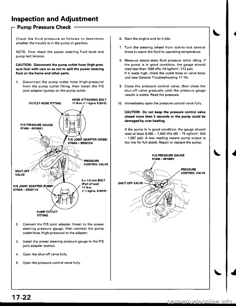
Check the fluid Dressure as follows to determine
whether the trouble is in the pump or gearbox.
NOTE; First check the power steering fluid level and
pump belt tension.
CAUTION: Disconnect the pump outlet hose (high-pres-
sure line) with care so as not to spill the power steering
fluid on the frame and other parts,
1. Disconnect the pump outlet hose (high-pressure)
from the pump outlet fitting, then install the P/S
joint adapter (pump) on the pump outlet.
P/S PRESSURE GAUGE07a06 - 001mo1
OUTLET HOSE FITTINGHOSE ATTACHING BOLT11 N.m (1.1 kgt.m 8lbl.ft)
PRESSURECONTROL VALVE
P/SAOAPTER IHOSEI07NAK - SR30124
6 x 1,0 mm BOLT
lP.n ol tooll'| 1 N.m
11.1 kgi.m,8lbtftl
PUMPFITTING
Connect the P/S joint adapter (hose) to the power
steering pressure gauge, then connect the pump
outlet hose (high-pressure)to the adapter.
Install the power steering pressure gauge to the P/S
joint adapter (pump).
Open the shut-off valve fully.
Open the pressure control valve fulli.
1.
Start the engine and let it idle.
Turn the steering wheel from lock-to-lock several
times to warm the fluid to operating temperature.
Measure steady-state fluid pressure while idling. lf
the pump is in good condition, the gauge should
read less than 1500 kPa (15 kgflcm'�,213 psi).
lf it reads high, check the outlet hose or valve body
unit (see General Troubleshooting 17-101.
Close the pressure control valve, then close the
shut-off valve gradually until the pressure gauge
needle is stable, Read the pressure.
lmmediately open the pressure control valve fully.
CAUTION: Do not keep the pressure control valve
closed more then 5 seconds or the pump could be
damaged by over-heating.
lf the pump is in good condition, the gauge should
read at least 6,400 - 7,400 kPa (65 - 75 kgflcm',924- 1,067 psi). A low.eading means pump output is
too low for full assist. Repair or replace the pump.
P/S PRESSURE GAUGE07i.{)6 - (x)l(xrol
9.
10.
SHUT.OFF VAI.VE
17 -22
{
I
Page 673 of 1681

Steering Wheel
Removal
Airbag Removal
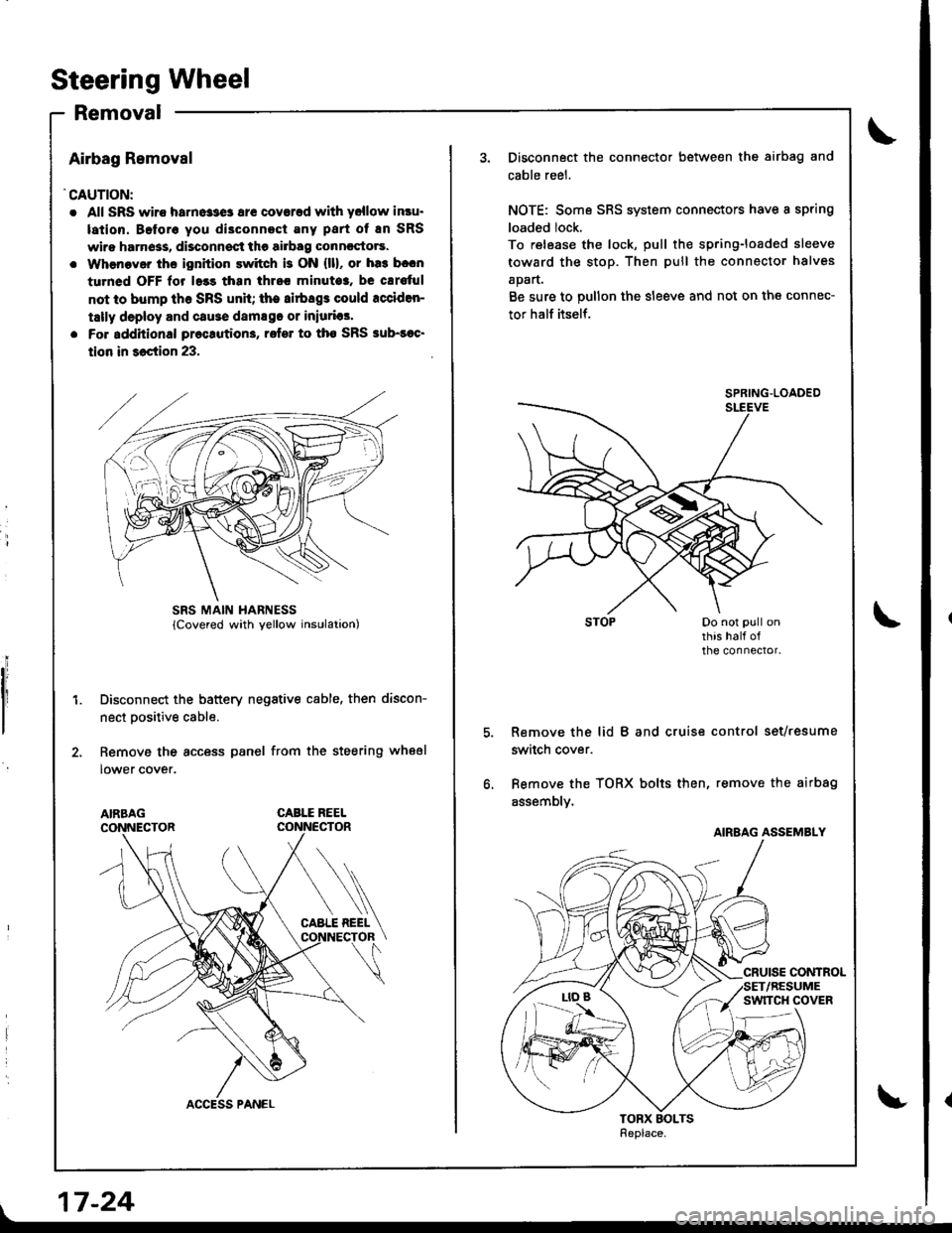
'CAUTION:
. All SRS wiro harne33e3 ar€ coverad with yellow insu.
lation. Beforo you di3connect Eny part of En SRS
wiro harn6ss, disconnsct the airbag conncctors.
. Whenaver ths ignition switch is ON {ll}, or ha3 b.cn
turned OFF lor l.3s than thrcc minuto3, be cErs{ul
not to bump th6 SRS unh; the airbags could rcciden-
tally deploy and cause damsgo or iniurias'
. Fo. additional preclution3, rofer to tho SRS sub-soc'
tion in 36ction 23,
Disconnect the battery negative cable, then discon-
nect Dositive cable.
Remove the access panel from the steering wheel
lower cover.
CABLE REEL
L
SRS MAIN HARNESS
17-24
Disconnect the connector between the airbag and
cable reel.
NOTE: Some SRS system connectors have a spring
loaded lock.
To release the lock, pull the spring-loaded sleeve
toward the stop. Then pull the connector halves
apart.
Be sure to pullon the sleeve and not on the connec-
tor half itself.
Remove the lid B and cruise control set/resume
switch cover.
Bemove the TORX bolts then, remove the airbag
assembly.
SPRING.LOADED
AIRBAG ASSEMBLY
Page 674 of 1681

Removal
Disconnect the connectors from the horn and cruise
control set/resume switches.
Remove the steering wheel nut.
Remove the steering wheel by rocking it slightly
from side-to-side as you pull steadily with both
hands. STEER|NG WHEEL
HORNCONNECTOR
7 -25
@ store a removed airbag assembly with
the pad surtace up. ll the airbag is improperly stored
tace down. accidental deployment could propel the unit
with snough force to cause serious iniury.
NOTE: lf an intact airbag assembly has been removed
from a scrapped car or has been found defective or
damaged during transit, storage or service, it should be
deDloyed (see section 23).
TORX BOLT9.8 N.m (1.0 kqt m, 6.5 lbf'ft)TORX BOLT9.8 N.m 11.0 kgf.m,6.5 lbf.ft)
CRUISE COTROL SET/RESUME SWITCHES
CAUTION:
Carefully inspect the airbsg assembly betore inst8ll-
ing. Do nol install 8n airbag assembly that shows
signs ot being dropped or improperly handled, such
as dents, cracks or deformation.
Oo not disassemble or tampel with the airb8g as-
sembly.
STEERING WHEEL
\@.
LID
h6
w1c4:,/bA
4t
SPACER
@f
CRUISE CONTROL SET/RESUME SWITCHES COVER
HORN CONTACT PLATE
Page 675 of 1681

Steering Wheel
lnstallation
Airbag installation
CAUTION:
. Before installing ths st€€ring wheel, align th€ front
wheels straight ahead.
. Be sure to ingtall the harnoss wirss 90 that they 8re
not pinched or intorfering with other car parts.
. Do not replace the original st€ering wheel with rny
other d8ign, since it will mako h impossiblo to p.op-
erly install the sirbag. {Only use genuinc HONDA
rephcamont parts)
. After rea$embly, contirm that ih€ wheels are still
st.ight 8head and that stooring wheel spoke angle
is correct. It minor spoko aogle sdiustment is n€cas-
sary. do so only by adiustment ol the tis-rods, not by
removing and reposhioning the 3teering who€|.
!@ confirm thst the airbag a33embly is
sscurely attached to th€ steering wheel; otherwi3e,
severe personal iniury could result during airbag
deploymenl.
1. Before instslling the steering wheel. center the
cable reel. Do this by first rotating the cable reel
clockwise until it stoos. Then rotate it counterclock-
wise (approximately two turns) until. The arrow
make on the cable reel label points straight up.
ARROW MARK
| 17-26
\
2. Installthe steering wheel.
NOTE: Be sure the steering wheel shatt engages
the cable reel and canceling sleeve.
CAUTION: Do not tap on ths stearing whool or
stsering column shaft whon in3tslling tha 3teoring
whs6l.
49 N'm ls.o kgf.m. 36 lbf'ftl
Aftach the cruise control sevresume switches con-
nector to the steering wheel clip.
Connect the horn conneclor,
CRUISE CONTROLSET,/RESUME SW]TCHESCONNECTOR
Page 677 of 1681

Steering Golumn
Removal
I
a All SRS wire harnesses are covered with yellow insu-
lation. Before vou disconnect any pan of an SRS wire
harness, disconnect the airbag Gonnectors.
a Whenever the ignition switch is ON (lll, or has been
turned OFF for less than three minutes, be carelul not
to bump the SRS unit; the airbags could accidentally
deploy and cause damage or iniuries.
a For additional precautions, lelel to the SRS sub-section
in section 23.
1. Remove the airbag assembly and steering wheel
(see page 17-25).
2. Remove the lower cover.
3. Remove the driver's knee bolster,
Remove the column covers by removing the
screws.
'//
,,1G
LOWER COVER
17 -28
1.
9.
Remove the SRS wire harness connector from the
connector holder.
Disconnect the cable reel connector and SRS main
wire harness connector (see page 17-24).
CONNECTOR HOI-DER
SRS WIRE HARNESS CONNECTOR
Disconnect the cruse control switch connector from
the cable reel, and remove the cable reel trom the
combination switch.
Remove the turn signal canceling sleeve.
Remove the combination switch from the steering
column by disconnecting the connectors.
Page 678 of 1681
10. Remove the steering joint cover.
Remove the steering joint bolts, and move the iointtoward the column.
11.
JOINT COVER
12.
'13.
Disconnect the ignition switch connectors from the
under-dash fuse/relay box.
Remove the steering column by removing the
aftaching nuts and bolts.
17-29
Page 679 of 1681

Steering Column
Inspection
Check the steering column ball bearing and the steer-
ing joint bearings for play and proper movement. ll
there is noise or if there is excessive plav, replace the
ioint or column assembly.
Check the retaining collar tor damage. lf ir is dam'
aged, replace the retaining coilar.
Check the absorbing plates, absorbing plate guides
and sliding capsules for distonion and breakage.
Replace them as an assembly if they are distorted or
DroKen.
ABSORBING PLATE
COLUMN SALL BEANING
IGNITION SWITCHsee section 23.
Move the tilt lever from the loose position to lock
position 3 to 5 times; then measure the tilt lever
preload 10 mm (0.4 in) from the end of the tilt lever.
Preload: 70-90 N {7 -9 kgl, 15-20 lbll
lf the measurement is out of the specification,
adjust the preload using the following procedures.
a. Loosen the tilt lever, and set the steering column
in the neutral position,
b. Remove the 6 mm lock bolt and remove the stop.
c. Adjust the preload by turning the tilt lock bolt left
or right.
d. Pull up the tilt lever to the uppermost position
and install the stop. Check the preload again. lf
the measurement is still out of specification,
repeat the above procedures (a) through (c) to
adjust.
CAUTION: Be carelul not to loosen the lilt lsvel
when installing the stop or tightening the 6 mm
lock bolt.
RETAINING COLLAR
AESORBING PLATE
JOINTBEARINGS
PLASTICINJECTIONS
This pan is attachedto the column bracketwith the plastic iniectaons.
t
SPRING SCALE
TILT LOCK BOLT
17-30
9.8 N.m (1.0 kst.m, 7.2 lblft)
t
{
I