Page 797 of 1681

l
DTC121416, 18: Wheel Sensor {Electrical Noise/lntermittent lnterruptionl
- Wilh the ignition switch ONlll), the ABS indicator doesnot go off.- With the SCS service connec-tor connectcd (3e6 page 19-37), DTCa 12, 14, 16, or 18.reindicated.
Visually check for appropriatewheel sensor and pulser installation (see table).
Reinstall or replace th6 eppropri-ats wh6el sensor or puber.
Ch€ck lor a short to wire in thoone wheel s6nsor circuit:1. Disconnect the ABS controlunit 22P connector.2. Measu re the resistancebetween the appropriatewheel sensor (+) and (-) circuit terminals (see table).
Repair short to wire between theappropriate wheel sensor {+) and{-l circuits.ls there less than 450 0?
Check lor a short to .nother wirein lhe wheel sensor circuits:Check for continuity between theappropriate wheel sensor (+) circuit terminal and other wheelsensor (+i circuit terminals (see
table)-
R€psir short to wire between theappropriale wheol sensor andthe other wheel sensor.ls there continuity?
Eraso the DTC and test-drive thevehicle. lf ABS indicator comeson and same OTC is indiceted,reDlace the ABS control unil.
NOTE: ll the ABS indicator comes on for the reasons described below, the indicator should go
off when you test'drive the vehicle at speeds above 19 mph 130 km/h).. Only the drive wheels rotated. The vehicle spun. Electrical noise
DTCAppropriate Wheel Sensor
12Right - front
14Left front
Right - rear
18Left rear
DTCAppropriate Terminal
{+}Side(-)Side
12 (Right-front)No. 9: FRW (+)No.8: FRW (-)
'14 {Left-front)No. 7: FLW {+)No.6: FLW (-)'16 {Right-rear)No. 19: RRW 1+)No.20: RRW ( )
18 (Left-rear)No. 17: RLW (+)No. 18: RLW ( )
DTCAppropriateTerminalOther Terminal
12 (Right-tront)No.9: FBW (+)No. 7: FLW 1+)No. 19: RRW (+)No. 17: RLW (+)
14 (Left-front)No.7: FLW (+)No.9i FRW (+)No. 19: RRW (+)No. 17: RLW (+)
16 (Right-rear)No. 19r RRW {+)No.9: FRW (+)No. 7: FLW 1+)No.17: RLW (+)'18 (Left-rear)No. 17: RLW (+)No.9: FRW (+)No.7; FLW (+iNo. 19: RRW (+i
'
L
19-45
Page 802 of 1681
- while driving and dcprc$ingtho brakc oodrl, the ABS indi-catot com63 0n.- With the SCS service connac-tor connoctod lsoa page 19-371, DTCa 41 - a4 ar6 indicri-oo,
Do the brakos drag?
Check the installation of theappropriate wheel sensor instal-lation (see table).
. Th6 orobablo cau3o was thevehicle spun during cornaring..lf the problem occurs agcin,chock th6 modulator u.ing thoHonda PGM Tertar.
DTCAppropriate Wheel Sensor
41Right-front
42Left-front
4:]Right-rear
44Leii-rear
Troubleshooting
DTC 41 - 44: WheelLock
19-50
Page 813 of 1681

Modulator Unit
Removal/lnstallation
CAUTION:
. Do not spill brake fluid on lhe vehicle; it may damage the paint; il brake fluid does contact the paint, wash it offimmediately with water.
. Tak€ care notto damage or delorm the brake lines during removal and installation.. To provont the brake fluid ftom flowing, plug and cover the hos€ ends and ioints with a shop towel or equiyalent material.
Removal
1. Disconnect the modulator unit and DUmD motor connectors.
2. Disconnect the brake lines, then remove the modulator unit.
Installation
1. lnstall the modulator unit, then connect the brake lines. Tighten the flare nuts to 15 N.m (1.5 kgf.m, 11 lbf.ft).2. Connect the modulator unit and pump motor connectors.
3. Bleed the brake system, starting with the front wheels.
4. Start the engine, and check that the ABS indicator goes off.
5. Test-drive the vehicle, and check that the ABS indicator does not come on.
From master cylinder
from master cylinderprimary side
PUMP MOTOB CONNECTOR
MOUNT
UNlT
MODULATOR UNIT CONNECTOR
toright front
8 mm EOLT22 N.m {2.2 kg[.m, 16 lbl.ftl
6 mm NUT9.8 N.m 11.0 ks{.m,7.2lbtftl
9-6
Page 814 of 1681
ABS Control Unit
RemovaUlnstallation
1. Remove the right quarter trim panel.
2. Disconnect the ABS control unit connectors.
3. Remove the ABS control unit.
Pulsers/Wheel Sensors
Inspection
/t
l\
I
Check the front and rear pulser for chipped or dam-
aged teeth.
Measure the air gap between tho wheel sensor and
pulser sllthe way around while rotating the pulser.
Standard: 0.4 - 1.0 mm (0.02 - 0.04 in)
NOTE: lf the gap exceeds 1.0 mm (0.04 in), the
probability is a distorted suspension arm which
should be reDlaced.
Front/R..1
L-TJ
.t-
t=
l-
Et-E_
Install the ABS control unit in the reverse order of
removal.
Start the engine, and check that the ABS indicator
goes off.
Test-drive the vehicle, and check that the ABS indi-
cator does not come on.
19-62
Page 1079 of 1681

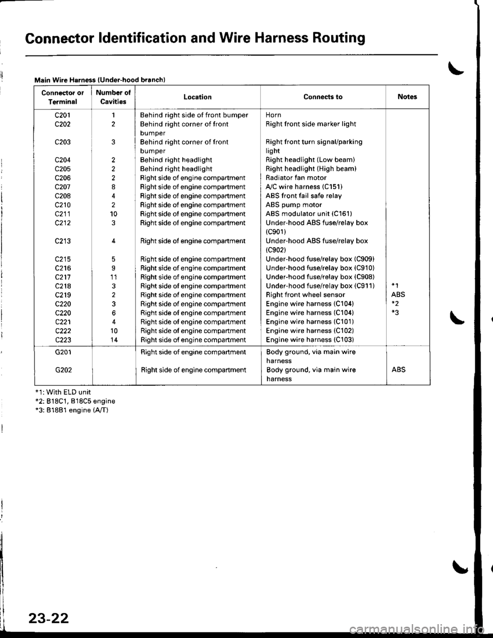
Connector ldentification and Wire Harness Routing
Main Wire Harness (Under-hood branchl
Conneqtor or
Terminal
Number ol
CavitiesLocationConnests toNotes
c201
c202
c203
c204
c205
c206
c207
c208
c210
c211
c213
c215
c216
c211
c218
c2r 9
c220
c220
c221
c222
c223
1
2
2
2
2
8
2
10
5
9'11
3
2
3
6
10
14
Behind right side of front bumper
Behind right corner of front
bumper
Behind right corner of front
DUmper
Behind right headlight
Behind right headlight
Right side of engine compartment
Right side of engine compartment
Right side of engine compartment
Right side of engine compartment
Right side of engine compartment
Right side of engine compartment
Right side ot engine compartment
Right side of engine compartment
Right side of engine compartment
Right side of engine compartment
Right side of engine compartment
Right side of engine compartment
Right side of engine compartment
Right side oI engine companment
Right side ot engine compartment
Right side ot engine compartment
Right side of engine compartment
norn
Right front side marker light
Right front turn signaUparking
lig ht
Right headlight (Low beam)
Right headlight (High beam)
Radiator lan motor
A"/C wire harness (C151)
ABS front fail safe relay
ABS pump motor
ABS modulator unit (C151)
Under-hood ABS fuse/relay box(c901)
Under-hood ABS fuse/relay box
{c902}
Under-hood fuse/relay box (C909)
Under-hood fuse/relay box (C910)
Underhood fuse/relay box (C908)
Under-hood fuse/relay box (C911)
Right front wheel sensor
Engine wire harness {C104)
Engine wire harness (C104)
Engine wire harness (C101)
Engine wire harness {C102)
Engine wire harness (C103)
*1
ABS
G201
G202
Right side of engine compartment
Right side of engine compartment
Body ground. via main wire
narness
Body ground, via main wire
harness
ABS
+1:With ELD unit*2: B18C't, 818C5 engine*3: 81881 engine (A,/T)
23-22
Page 1099 of 1681
Connector ldentification and Wire Harness Routing
IABS Sub-harness
Connestor or
Tcrminsl
Number of
CavitiesLocationConneqts toNotos
c701
c703
c704
c705
c705
c706
c706
12
22
2
2
2
Behind right kick panel
Right quarter panel
Right quarter panel
Right side of cargo area
Right side of trunk
Left side of cargo area
Left side of trunk
Main wire harness (C407)
ABS control unit
ABS control unit
ABS right rear wheel sensor
ABS right rear wheel sensor
ABS left rear wheel sensor
ABS left rear wheel sensor
Hatchback
Sedan
Hatchback
Sedan
G702Right quarter panelBody ground, via ABS sub-harness
Page 1380 of 1681

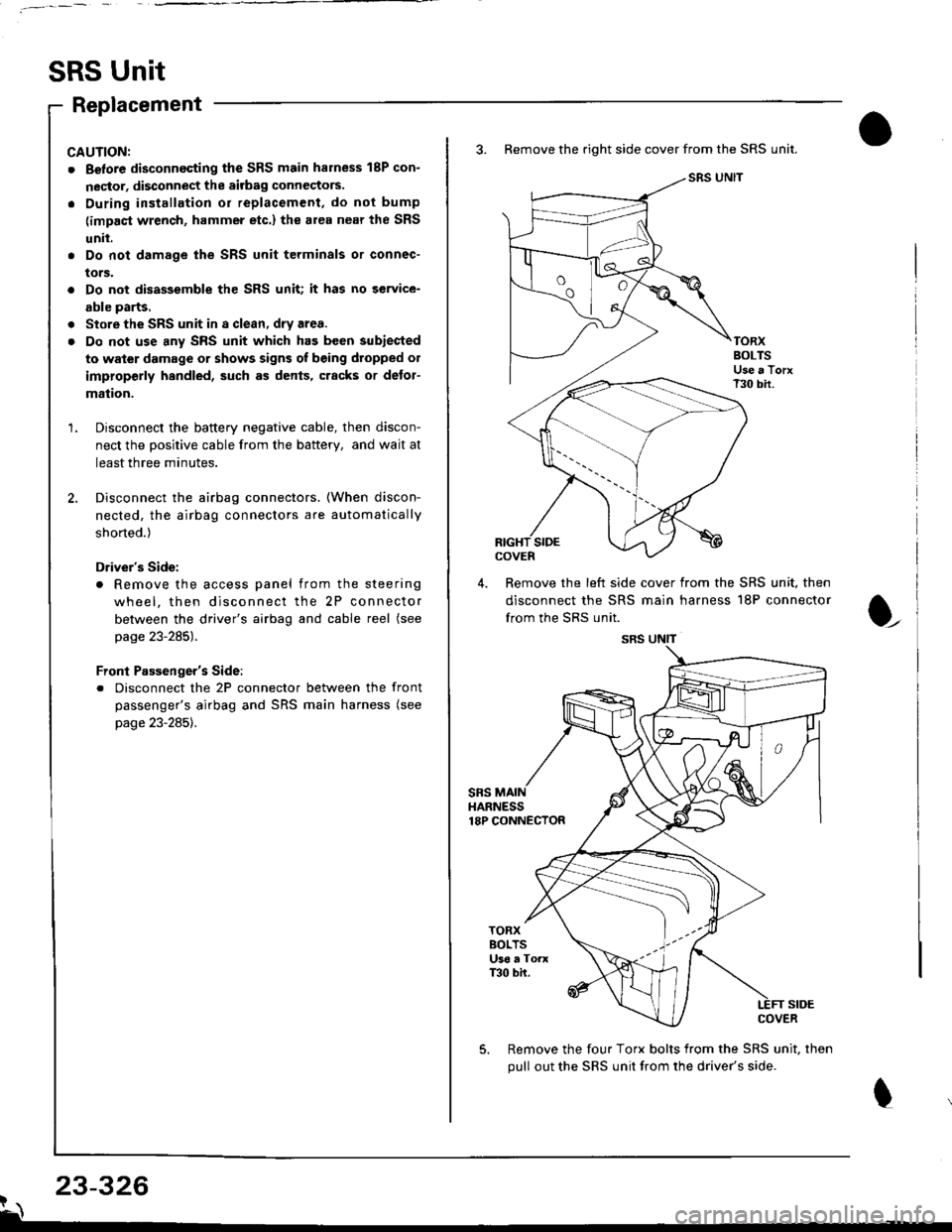
SRS Unit
Replacement
CAUNON:
. Betore disconnecting the SRS main harness 18P con-
nector, disconnect the aitbag connectors.
. During installation or replacement, do not bump
(impact wrench, hammer etc.) the al€a near the SRS
unit.
. Do not damage the SRS unit terminals or connec-
tors.
. Do not disassemble the SRS unit; it has no service-
able parts.
. Store the SRS unit in a clean, dry area.
. Do not use any SRS unit which has been subiected
to water damage or shows signs of being dtopped ol
improperly hsndled, such as dents, cracks or detor-
mation.
Disconnect the baftery negative cable, then discon-
nect the positive cable from the battery, and wait at
least three minutes.
Disconnect the airbag connectors. (When discon-
nected. the airbag connectors are automatically
shorted.)
Driver's Side:
. Remove the access panel from the steering
wheel, then disconnect the 2P connector
between the driver's airbag and cable reel (see
page 23-285).
Front Passenger's Side:
. Disconnect the 2P connector between the front
passenger's airbag and SRS main harness (see
page 23-285).
3. Remove the right side cover from the SRS unit.
SRS UNIT
TORXBOLTSUse a TorxT30 bir.
SIDEcovEn
4. Remove the left side cover from the SRS unit, then
disconnect the SRS main harness 18P connector
from the SRS unit.
sRsHARNESS18P CONNECTOR
t
TORXBOLTSU36 a ToaxT30 bh.
SIDECOVER
Remove the four Torx bolts from the SRS unit, then
pull out the SRS unit from the driver's side.
23-326?\
SRS UNIT
Page 1381 of 1681
6, Install the new SRS unit.
o^ l- o
9.8 N.m 11.0 kgf m, 7.2Use a Torx T30 bit.
I
TORX BOLTS9.8 N.m 11.0 kgl.m, 7.2 lbf'ftlUse a Torx T30 bit.
7.Connect the SRS main harness l8P connector to the
SRS unit; push it into position until it clicks.
Install the SRS unit covers (right and left) Make
sure the covers snap together in the middle.8.
,l
\
10.
Reconnect the driver's airbag 2P connector to the
cable reel 2P connector, then reinstall the access
panel on the steering wheel.
Reconnect the front passenger's airbag connector
to the SRS main harness.
Reconnect the battery positive cable, then the nega-
tive cable.
After installing the SRS unit, confirm proper system
operation: Turn the ignition switch ON (ll); the SRS
indicator light should come on for about six seconds
and then go off.
11.
12.