Page 161 of 1681
t
Installation
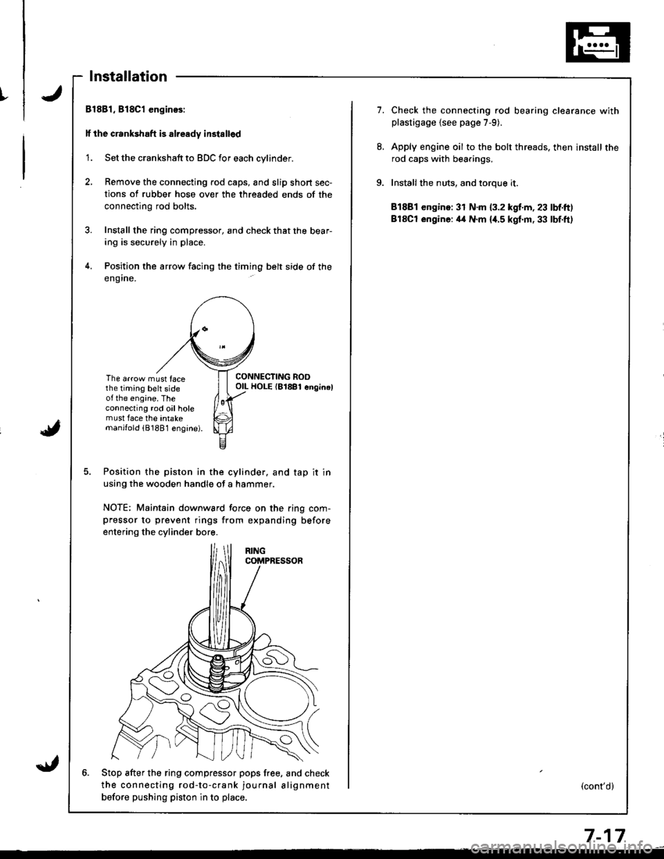
Bl881, 818C1 enginos:
lf the crankshaft is already installed
'1. Set the crankshaft to BDC for each cylinder.
2, Remove the connecting rod caps, and slip short sec-
tions of rubber hose over the threaded ends of the
connecting rod bolts.
3. Install the ring compressor, and check that the bear-
ing is securely in place.
4. Position the arrow facing the timing belt side of the
eng ine.
The arrow must facethe timing belt sideot the engine. Theconnecting rod oil holemust face the intakemanjfold (81881 engine).
CONNECTING ROOOIL HOLE {81881 enginel
Position the piston in the cylinder. and tap it in
using the wooden handle of a hammer.
NOTE; Maintain downward force on the ring com-pressor to prevent rings from expanding before
entering the cylinder bore.
6. Stop after the ring compfessor pops free, and check
the connecting rod-to-crank journal alignment
betore pushing piston in to place,
7.Check the connecting rod bearing clearance withplastigage {see page 7-9).
Apply engine oil to the bolt threads. then install the
rod caps with bearings,
Installthe nuts, and toroue it.
81881 engine: 31 N.m {3.2 kgf.m, 23 lbf.ft)
BlSCt engine: il4 N.m {i[.5 kgf.m, 33 lbf.ft)
(cont'd)
7-17
Page 162 of 1681
I
i
Pistons
Installation (cont'dl
ll the crankshaft is not installed
1. Remove the connecting rod caps, then install the
ring compressor. and check that the bearing is
securely in place.
2. Position the arrow and the mark facing the timing
belt side of the engine.
ItIl
Iti
tfll|lflI[lrB
[:
i"lrt
i'
ff
ll,
illi
llillr
il
The arrow must facethe timing belt sideof the engine. Theconnecting rod oil holemust face the intakemanilold (8188'l engine).
Position the piston in the cylinder, and tap it in
using the wooden handle of a hammer.
NOTE: Maintain downward force on the ring com-
pressor to prevent rings from expanding before
entering the cylinder bore.
Position all pistons at top dead center.
7-18
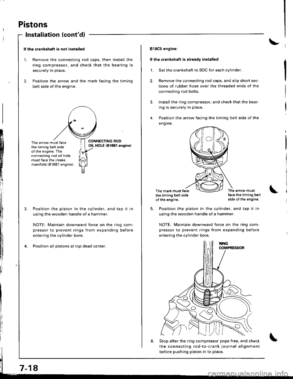
818C5 engine:
ll the crankshaft is already installed
1. Set the crankshaft to BDC for each cylinder.
2. Remove the connecting rod caps, and slip short sec-
tions of rubber hose over the threaded ends of the
connecting rod bolts.
3. Install the ring compressor, and check that the bear-
ing is securely in place.
4. Position the arrow facing the timing belt side of the
eng ine.
The mark must facethe timing belt sideof the engine.
The arrow mustlace the timing beltside of the engine.
Position the piston in the cylinder, and tap it in
using the wooden handle of a hammer.
NOTE: Maintain downward iorce on the ring com-
pressor to prevent rings from expanding before
entering the cylinder bo.e.
6. Stop after the ring compressor pops free, and check
the connecting rod-to-crank journal alignment
before pushing piston in to place.
Page 163 of 1681
I
7.
8.
9.
Check the sonnecting rod bearing clearance withplastigage (see page 7-9).
Apply engine oil to the bolt threads, then install the
rod caps with bearings.
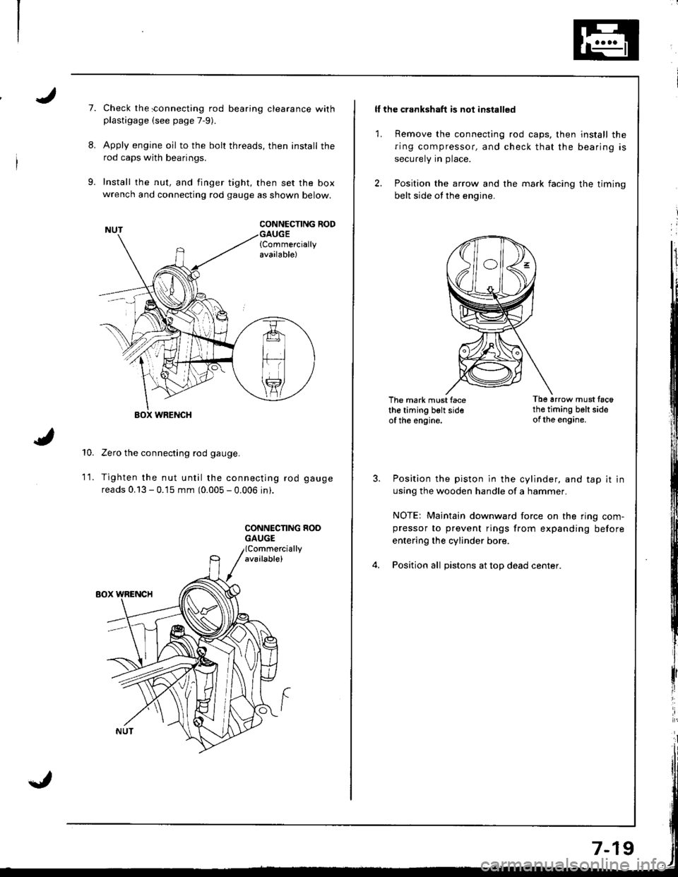
Install the nut, and finger tight, then set the boxwrench and connecting rod gauge as shown below.
CONNCCNNG RODGAUGE{Commerciallyavailable)
10.
WRENCH
Zero the connecting rod gauge.
Tighten the nut until the connecting rod gauge
reads 0.13 - 0.15 mm (0.005 - 0.006 in).
CONNECNNG HOOGAUGE
1t.
ll the crankshaft is not installed
1. Remove the connecting rod caps, then install the
ring compressor, and check that the bearing is
securely in place.
2. Position the arrow and the mark facing the timing
belt side ot the engine.
The mark must facethe timing belt sideof the engine.
Tb6 arrow must tac6th€ timing belt sideof the engine.
Position the piston in the cylinder, and tap it in
using the wooden handle of a hammer.
NOTE: Maintain downward force on the ring com-pressor to prevent rings from expanding before
entering the cylinder bore.
Position all pistons at top dead center.
Page 164 of 1681
Piston Rings
Replacement
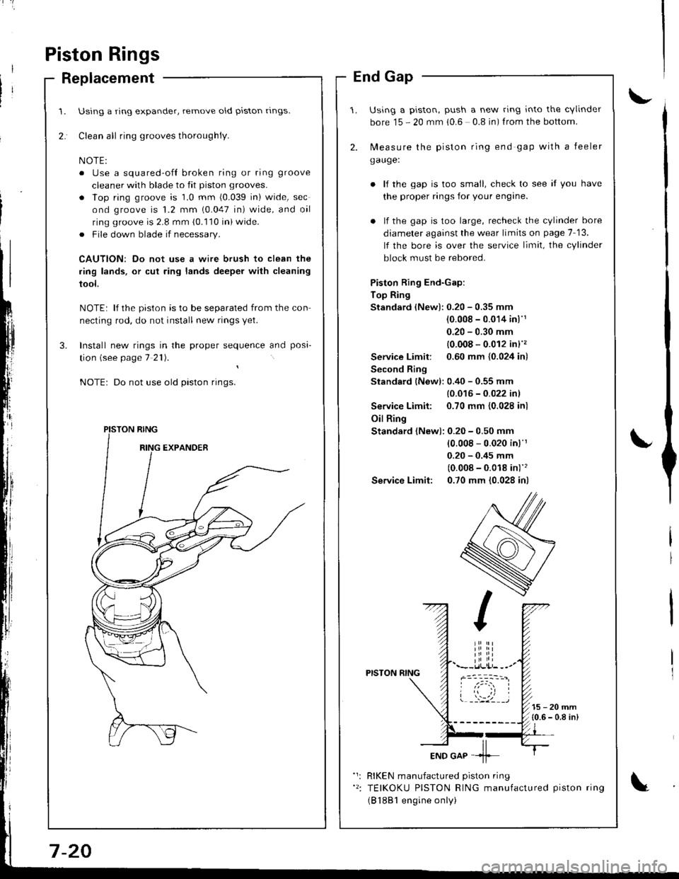
Using a ring expander, remove old piston rlngs.
Clean all ring grooves thoroughly.
o Use a squared-ofl broken ring or ring groove
cleaner with blade to fit piston grooves.
. lop ring groove is 1.0 mm (0.039 in) wide, sec
ond groove is 1.2 mm (0.047 in) wide, and oil
ring groove is 2.8 mm (0.110 in) wide.
. File down blade if necessary.
CAUTION: Do not use a wire brush to clean the
ring lands, or cut ring lands deeper with cleaning
tool.
NOTE: lf the piston is to be separated from the con
necting rod, do not install new rings yet.
Install new rings in the proper sequence and posa-
tion (see page 7 21).
Do not use old piston rings.
PISTON RING
End Gap
Using a piston, push a new ring into the cvlinder
bore 15 - 20 mm 10.6 0.8 in) f rom the bottom.
2. N,4easure the piston ring end gap with a feeler
gauge:
lf the gap is too small, check to see if you have
the proper rings for your engine.
. lf the gap is too large, recheck the cylinder bore
diameter against the wear limits on page 7-13.
lf the bore is over the service limit, the cylinder
block must be rebored.
Piston Ring End-Gap:
Top Ring
Standard (New):0.20 - 0.35 mm
(0.008 - 0.014 inl'1
0.20 - 0.30 mm
{0.008 - 0.012 in}''�
Service Limit: 0.60 mm {0.024 in)
Second Ring
Standard {New): 0.40 - 0.55 mm
{0.016 - 0.022 inl
Service Limit: 0.70 mm {0.028 inl
Oil Ring
Standard (New): 0.20 - 0.50 mm
10.008 - 0.020 in)'r
0.20 - 0.45 mm
(0.008 - 0.018 in)''�
Service Limit: 0.70 mm (0.028 in)
PISTON RING
15-20mm{0.6 - 0.8 in)
RIKEN manufactured piston ring
TEIKOKU PISTON RING manufactured piston ring
(B 1881 engine only)
Page 170 of 1681
t'
Crankshaft
lnstallation
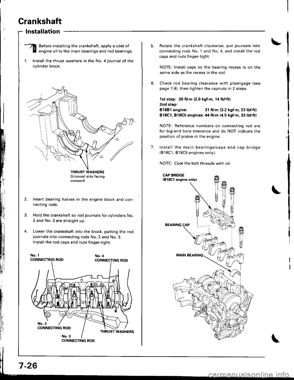
-Q Before installing the crankshaft, apply a coat of
E engine oilto the main bearings and rod bearings.
1. lnstall the thrust washers in the No. 4 iournal of the
cylinder block.
Grooved side facingoutwaro,
Insert bearing halves in the engine block and con-
necflng roos.
Hold the crankshaft so rod journals for cylinders No.
2 and No.3 sre straight up.
Lower the crankshaft into the block, putting the rod
iournals into connecting rods No.2 and No.3.
Installthe rod caps and nuts finger-tight.
No. 1No. 4
CONNECTING ROO
7-26
1.
Rotate the crankshaft clockwise, put journals into
connecting rods No. 1 and No.4, and install the rod
caps and nuts tinger-tight.
NOTEI lnstall caps so the bearing recess is on the
same side as the recess in the rod.
Check rod bearing clearance with plastigage (see
page 7-9), then tighten the capnuts in 2 steps.
lst step: 20 N.m (2.0 kgf m, 14 lbf.ftl
2nd step:
81881 engine:31 N.m (3.2 kgf.m, 23 lbf.ftl
818C1,818C5 enqines:44 N.m (4.5 kgf.m,33 lbt.ftl
NOTE: Reference numbers on connecting rod are
tor big-end bore tolerance and do NOT indicate the
position of piston in the engine.
Install the main bearings/caps and cap bridge(818C1, 818C5 engines only).
NOTE: Coat the bolt threads with oil
CAP BRIDGE{B18Cl engine onlyl
BEARING
MAIN BEARING
fi
U
t{
T
!+
T1
Page 171 of 1681
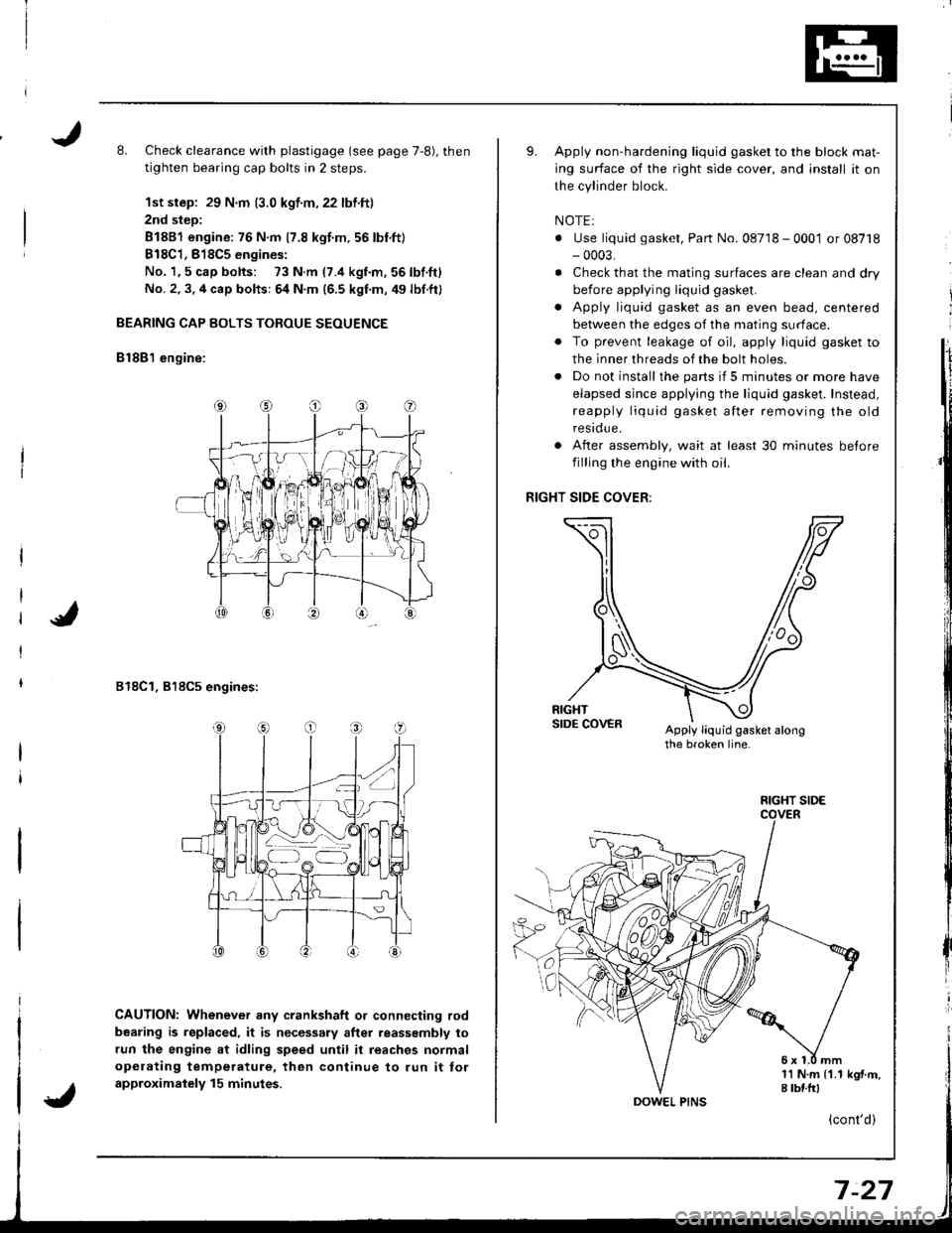
L Check clearance with plastigage (see page 7,8), then
tighten bearing cap bolts in 2 steps.
1st step: 29 N.m (3.0 kgf.m,22 lbf.ft)
2nd step:
81881 engine: 76 N.m 17.8 kgt.m.56 lbnft)
B18C1,818C5 engines:
No. 1,5 cap bolts: 73 N.m (7.4 kgnm,56lbf.ft)
No. 2, 3. 4 cap bolts: 64 N.m (6.5 kgf.m, 49 lbf.ft)
BEARING CAP BOLTS TOROUE SEOUENCE
B lSB'l engine:
818C1, 818C5 engines:
CAUTION: Whenever any crankshaft o. connecting rod
bearing is replaced, it is necessary after reassembly to
run the engine at idling speed until it reaches normal
opelating temperature, then continue to run it tor
approximalely 15 minutes.
Apply non-hardening liquid gasket to the block mat-
ing surface of the right side cover, and install it on
the cylinder block.
NOTEI
. Use liquid gasket, Part No. 08718 - 0001 or 08718- 0003,
. Check that the mating surfaces are clean and dry
before applying liquid gasket.
. Apply liquid gasket as an even bead, centered
between the edges of the mating surface.
. To prevent leakage of oil, apply liquid gasket to
the inner threads of the bolt holes.
. Do not install the parts if 5 minutes or more have
elapsed since applying the liquid gasket. Instead,
reapply liquid gasket after removing the old
residue.
After assembly, wait at least 30 minutes betore
filling the engine with oil.
RIGHT SIDE COVER:
Apply liquid gasket alongthe broken line.
o
a
1l N.m {1.1 kgf.m,I tbf.frl
FIGHT SIDE
(cont'd)
Page 172 of 1681
Crankshaft
Installation (cont'd)
I
I
t
l;I
I
fi,
\
10. Apply non-hardening liquid gasket to the block mat
ing surface of the oil pump, and install it on the
cylinder block.
11. lnstall the oil screen.
OIL PUMP:
Apply liquid gasket alongthe broken line.
5x1.0mm11N.m 11.1 kgt.m,8 tbtftl
GASKETReplace.
?,' /'\, /s.../
11 N.m {1.I kgf.m,
DOWEL PIN
o-ntNG
/\
/
':'
Apply engine oil.Replace.8 x 1.25 r\m24 N.m (2.4 kgt.m,17 tbf.ft)OIL PUMP
Apply liquid gasket on oil pump and right side
cover matinq areas as shown below.
CYLINDERBI_OCK Apply liquid gasket
RIGHT SIDECOVERApply liquid gasket
to lhese potnts-
to these points.
Install the oil pan gasket and oil pan.
NOTEr Use a new oil pan gasket.
Tighten bolts and nuts finger tight at six
shown below.
points as
Tighten all bolts and nuts stating from bolt O clock-
wise in three steps.
NOTE: Excessive tightening can cause distortion of
oil pan gasket and oil leakage.
Torqus: 12 N.m (1.2 kgf.m,8.7 lbf'ftl
14.
Page 181 of 1681

Oil Filter
Replacement (cont'd)
Install the oil filter by hand.
After the rubber seal seats, tighten the oil
clockwise with the special tool.
Tighten: 7/8 turn clockwise.
Tightening torque:22 N m (2.2 kgf m,'16 lbf ftl
tilte r
OIL FILTER WRENCH
8-8
Eight numbers (1 to 8) are printed on the surlace ol
the filter.
The lollowing explains the procedure for tightening
filters using these numbers.
1) Make a mark on the engine oil cooler (818c5
engine) or cylinder block (8188'1, 818C1 engines)
under the number that shows at the bottom of
the filter when the rubber seal is seated.
2) Tighten the filter by turning it clockwise seven
numbers Irom the marked point. For example, if a
mark is made under the number 2 when the rub
ber seal is seated, the filter should be tightened
until the number 1 comes up to the marked point
818C5 engine:
B1881, 818C1 engines:
Number when rubber
seal is seated.Number after tightening
MARK
MARK
Number when rubber
seal is seated
'I2345678
Number after tightening812561
5. After installation, fill the engine with oil up to the
specilied level, run the engine for more than 3 min-
utes, then check for oil leakage and oil level.
CAUTION: Installation using other than the above
procedure could result in serious engine damage
duo to oil leakage.