Page 1427 of 1681
Ground Distributioh (cont'd)
- G503 (Sedan)
NOTE: Wkes shown without color codes are black.
LEFTIN NERBRAKELEFT LIGHT/BACK-UP TAILLIGHTLIGHT Paqes 110-7Paqe 110,1 and 110-13
r-,r ,--r\_,, r- -,
c534
L.JLIJL.J
TRAILERLIGHTINGCONNECTORPage 118
RIGHTINNERBRAKELIGHT/TAILLIGHTPages 110-7and 110-13
()
RrcHr l!-c.{r !'rqlt-
!iTfi^. iff#"" iilt[i",
b:::1,0. ii3:3 :i3::lts'
(:) (:) rllr
TRUNKLATCHswtTcHPage 114-3
tl
tl
2 Y C535
RIGHTBACK-UPLIGHTPage 110 1
/\
LEFTREARTURNSIGNALLIGHTPage 110-5
LEFTREARPARKINGLIGHTPage110-13
/\
LEFTOUTERBRAKELIGHT/TAILLIGHTPages 1'10-7and 110-13
()
'98-'�99
Model
(Notuseo)
cs22
HIGHMOUNTBRAKELIGHTPage 110-7
tl
REARwrNDowDEFOGGERPage 64
ll
14-8
Page 1453 of 1681
Cruise Control
Ft sE 14
{crulsE CO}nnoL}
------ 2J =r*--i
(Not Used)
lhy
I input \'t
L------- ______J
UNDER.DASHFUSE/RELAYBOXI
" | ,c#:.*12c551
CRUISECONTROLMAINswrTcH
-:1, c555
neo I
I
See Dash andConsole Lights
2
LT GFN
2
ITGRN
c452
'l*.'
"*l
_J".,,--B'"*-3----7
s$/itch IPoti,efinout
'l------------ 19
t:-:----. rgnluon
I input
oiaie peoar f----1depressed. f--
Open with
BLKYEL
34
Page 1455 of 1681
Cruise Control (contd)
.I UNDER-
* = '98-'99 lvlodels
DASHFUSE/RELAYBOX
T
!
l
L10YEUBLU
YEL/BLU
See Dashand ConsoleLights
See IndicatorsGAUGEASSEMSLYCRUISECONTROL
"Cruise control'Indicator tght control l-
Cruise control acluator control \
BRN/FEO I ABN'BLK T aRNAA/HT
rr g-----:^1f --'rf, csoz1oy s y iio",'o,,BFN/FED I BFN'BLK f BRN^n/HT
o A_____r_A s__l csrswxr I sru I """|'PrJic ''
CRUISECONTROLACTUATOR
8LK1
BLK8LK
S€e Grolnd
a-< page 14'3.
Or-< Distibution,
|
*n;'"
e.^l I
!---J- PHOTO 56
See GroundDistribution,
: c301
! | Dimminscrrcurt |� lISiPto" !I r I r e r:::::_ |
| ,,31 f---- see Indicators -^\J'llclultl | :
L------:-:Y----- -----sLt-95-.i':::f----
I 3:3"9i;,To o'"o,0',,""'
"'^|,2-.-.I
g.. c+or- D4OIO.6 9
34-2
Page 1457 of 1681

Cruise Control (cont'd)
- How the Circuit Works
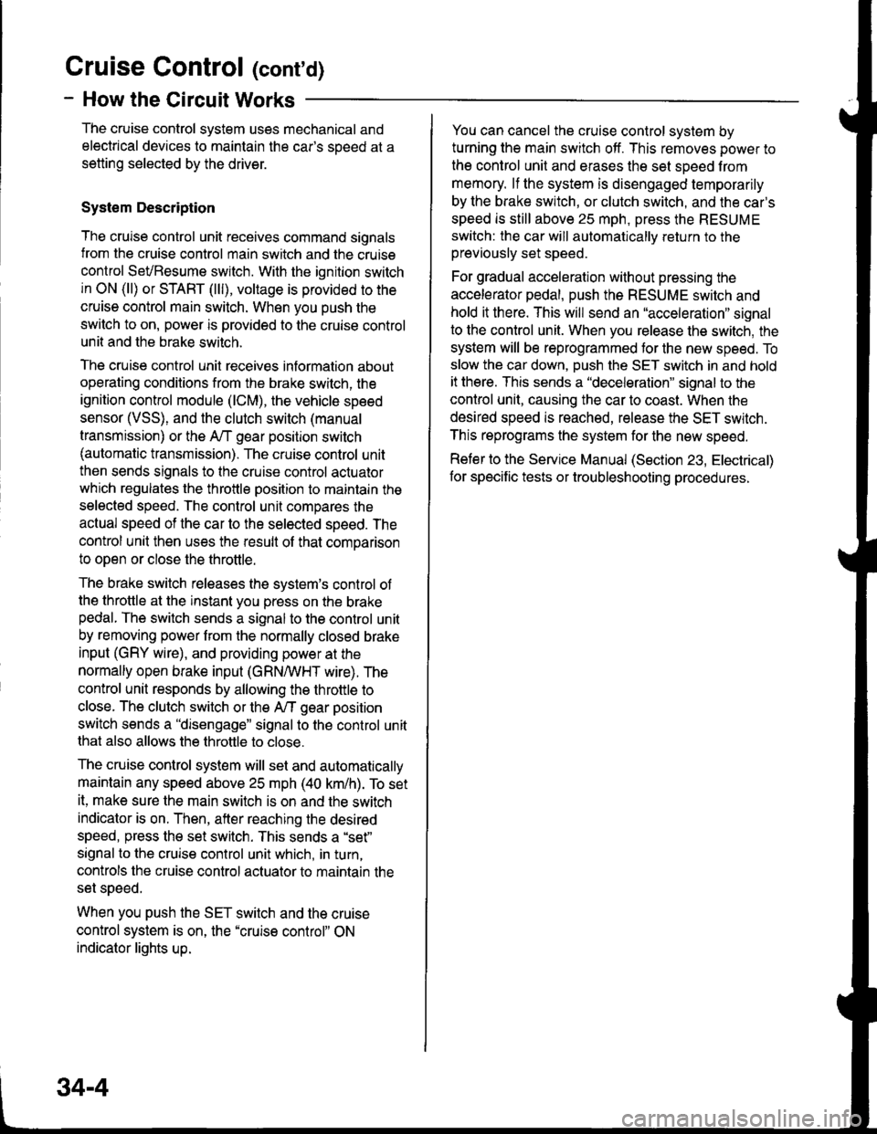
The cruise control system uses mechanical and
electrical devices to maintain the car's soeed at a
setting selected by the driver.
System Description
The cruise control unit receives command signals
from the cruise control main switch and the cruise
control SevBesume switch. With the ignition switch
in ON (ll) or START (lll), voltage is provided to the
cruise control main switch. When you push the
switch to on, power is provided to the cruise control
unit and the brake switch.
The cruise control unit receives information about
operating conditions from the brake switch, the
ignition control module (lCM), the vehicle speed
sensor (VSS), and the clutch switch (manual
transmission) or the A,/T gear positton switch
(automatic transmission). The cruise control unit
then sends signals to the cruise conirol actuator
which regulates the throttle position to maintain the
selected speed. The control unit compares the
aclual speed of the car to the selected speed. The
control unit then uses the result of that comoarison
to oDen or close the throttle.
The brake switch releases the system's control of
the throttle at the instant you press on the brakepedal. The switch sends a signal to the control unit
by removing power from the normally closed brake
input (GRY wire), and providing power at the
normally open brake input (GRNMHT wire). The
control unit responds by allowing the throttle to
close. The clutch switch or the A/T gear position
switch sends a "disengage" signal to the control unit
that also allows the throttle to close.
The cruise control system will set and automatically
maintain any speed above 25 mph (40 km/h). To set
it, make sure the main switch is on and the switch
indicator is on. Then, after reaching the desired
speed, press the set switch. This sends a "set"
signal to the cruise control unit which, in turn,
controls the cruise control actuator to maintain the
set soeed.
When you push the SET switch and the cruise
control system is on, the "cruise control" ON
indicator lights up.
34-4
You can cancel the cruise control system by
turning the main switch off. This removes power to
the control unit and erases the set sDeed from
memory. lf the system is disengaged temporarily
by the brake switch, or clutch switch, and the car's
speed is still above 25 mph, press the RESUME
switch: the car will automatically return to the
previously set speed.
For gradual acceleration without pressing the
accelerator pedal, push the RESUME switch and
hold it there. This will send an "acceleration" signal
to the control unit. When you release the switch, the
system will be reprogrammed tor the new speed. To
slow the car down, push the SET switch in and hold
it there. This sends a "deceleration" signal to the
control unit, causing the car to coast. When the
desired speed is reached, release the SET switch.
This reprograms the system for the new speed.
Reter to the Service Manual (Section 23, Electrical)
for specific tests or troubleshooting procedures.
Page 1462 of 1681
Automatic Transmission Controls
- '00 Model
47n
24
FUSE 4AACX UE(8ADrO)
c2't7
'r,
Ir.g
l
See PowerDistribution,pag€ 1G9.
FUSE 52HOBfl, SIOP204
UNDER-HOODFUSE/BELAYBOX
c418Oerminals 15.17)
8
WHT/AIU
aa+See PowerDistfibution,page 10"8.
I
$See ABS,Brake Lights,Cruise Control
. B2t 432r--rsrbFswlIBattery back-up Btake switch input i
Shift lock Shilt conkol solenoid Lock-up control solenoid Linear solenoid \Vehicte JirCuif ly'C on valve control valve control valve eontrol Isoeed inDut control inDut !speed input control inputlvss) {rLUl tacoLl {SH B, rSH A' {LC A) (LC B) {L.s+J (LS ) Ic23 A2A At7 02 D7 Dl D3 817 8a -'c23 A28 A17 02 D7 D1 D3 817 88
T-lF$ffiT-il:
::m]'::.
1j$;$d.H-t,il: Tfl;;
ill}.-.'.-":[-{,* 'ffi; -lTl.'
i[fi;"
":ff":'[:{;,[fi::
iy:[*i xFEf"* llrTril ilfinpl -l-
"'i-f1.o"^.,,
i i--i , !r.Eli- -
L'q,j ;:i5?" *'.,
|
"ll!
i ll
I tf.f$sb
E W *$+iir [E''l
5i'i+r" "
I see venicre
-
|_
- -T ;'r'o'i;
i;*
**'""::.";
I
""
l'tr .,,,
"^::'[",,
39-4
Page 1471 of 1681

Supplemental Restraint System (SRS)
FUSE 13FUEL PUIIP(SRS UNF)t5a
FUS€ 23(s8s)
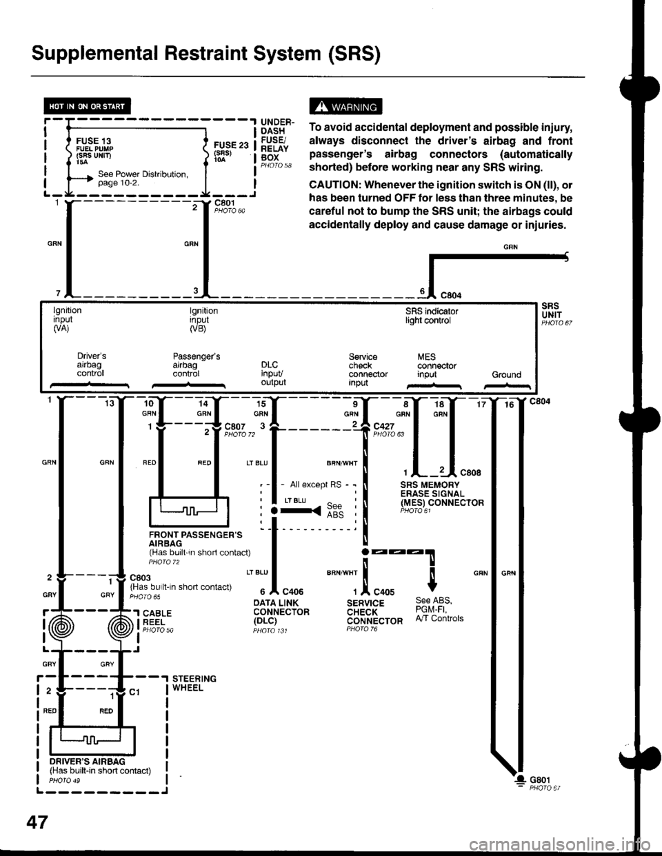
ts13t5" To avoid accidental deployment and possible iniury,
lq9Fr. always disconnect the driver's airbag and frontg[f" pas"Lnger's airbag connectors (automaticallyPHorQ 58 shorted) before working near any SRS witing.
CAUTION: Whenever the ignition switch is ON (ll), ol
has been turned OFF tor less than three minutes, be
careful not to bump the SRS unit; the airbags could
accidentally deploy and cause damage or iniuries.
{-
lgnitionrnpul(VA)
tgnitionInpul(VB)
Passenger'sarrbagcontrol
SFIS indicaiorlight control
Service MEScheck @nnectorconnector input GroundInpu
Driver'sarrbagconlr0lDLC'npuvoutput
-ro--Y---la-Y--- 16
:ffi*f:ffq
lJnor,rrpassencen= 'l t- 'i
rHas bu,ll 'n shorl contac0
I j:::T
fn'"o"t. n-n .non "on,""u
" "'Jl
"oou
""" ""]
.!, "oou $
cRN
: :3<::" :l (Y.e_er
oArA LINK sERvrcE 9qe l-qs,'l SABLE coHrecibn aH;a'i- ?9q1i iEEi- 1ot-i1 cijrlt't'ecron n/r contrors
I Pt:OfO 5a pqara t Jt PForo 76
I
STEERINGWHEEL
1
GRY
ON|vER'S AIRBAG(Has built-in short contact)
L---------J
47
GBY
r
I
I
GRY
2
NED
Page 1479 of 1681

A/C Gompressor Controls (conrd)
- How the Circuit Works
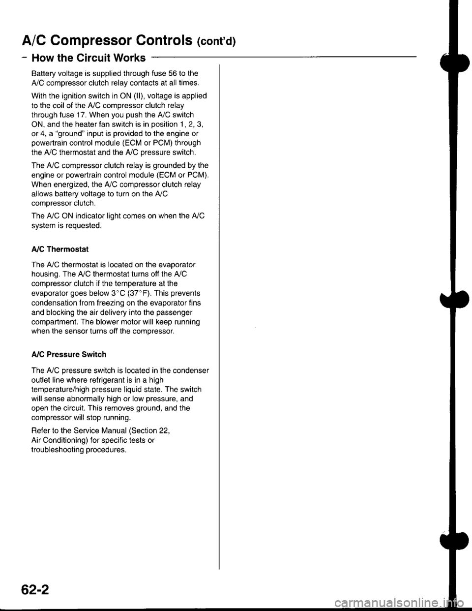
Battery voltage is supplied through fuse 56 to the
A,/C compressor clutch relay contacts at all times.
With the ignition switch in ON (ll), voltage is applied
to the coil of the A,/C compressor clutch relay
through fuse 17. When you push the A,/C switch
ON, and the heater fan switch is in posation 1, 2, 3,
or 4, a "ground" input is provided to the engine or
powertrain control module (ECM or PCM) through
the A,/C thermostat and the A,/C pressure switch.
The A,/C compressor clutch relay is grounded by the
engine or powertrain control module (ECM or PCM).
When energized, the A,/C compressor clutch relay
allows battery voltage to turn on the A,/C
comDressor clutch,
The A,/C ON indicator light comes on when the A"/C
system is requested.
A,/C Thermostat
The A,/C thermostat is located on the evaoorator
housing. The AJC thermostat turns off the A,/C
compressor clutch if the temperature at the
evaporator goes below 3'C (37'F). This prevents
condensation from freezing on the evaporator fins
and blocking the air delivery into the passenger
compartment. The blower motor will keep running
when the sensor lurns off the compressor.
A,/C Pressure Switch
The A,/C pressure switch is located in the condenser
outlet line where refrigerant is in a high
temperature/high pressure liquid state. The switch
will sense abnormally high or low pressure, and
open the circuit. This removes ground, and the
compressor will stop running.
Refer to the Service Manual (Section 22,
Air Conditioning) for specific tests or
troubleshooting procedures.
62-2
Page 1484 of 1681
H"ar ffndow Defogger
---.I UNDER.
i-I,;.;;lH8B'J i
illk.**"llieF iL-Ja---J PEoro 21 L
I DASH
i FUSE/I RELAYI Box
FUSE 16NEAR DEFROSI€B NEIAY7.54
__J PHO|O sA
[._
See Dashand ConsoleLights
Y
"ao,"a" I
--g-,1 cser
c2172
ALK/BLU
'T 9#.'9,,BTruBLU
i
"r'u"au !
@cREARwtNDowDEFOGGERswtTcH
See PowerDistribution,pago 1G6.
c422
UNDER-DASHFUSE/RELAYBOX
S€e GroundDistribution,page 14-5.
:ffilfi$Eijc914Hatchback t1
-----l".* o"nf, L----
f ;fl,:" "onn"",o., -",
I not be presenl in allcars.)
BL|(GRN
I
I
I "u.o
l-lFl REARI .5 | WTNDOW
lll
oEFoGGER
,.^f "tt'
"";',u'," i il{:{'}Fl
l'*'**T.lJ: PHoTo 102
c753
1 REARI WINDOW
I DEFOGGERIJ BLIIGRNc771
1
BLK/GFN
rII
G?7.1 L
".of,or"i:
BU( ltGFNA c516
'." ! 1]ll'.llGRN ll pre6e
2 J C525BL|! ll P,lorc
neof czss
msi
lllo'Y c771
BLK
BLK
cs16(ln-line connectorlmay not bepresent in allcars.)
"..1
t
REARwtNDow
swlTcHLIGT'Toila_
ONINDICA.TOR
ry$:F*
::";,=.4
-
: :
-L[; - -
T
- - - - -
I
iiffit]lffi**'
BLKBLU
64