Page 1416 of 1681
![HONDA INTEGRA 1998 4.G Workshop Manual Power Distribution
- From Fuses to Relays and Components (contd)
rll
FUSE 48 \HEAruCHT \{la \
II-------Jc216c217
::]:I
-..
3
ir
:l
:!, I tFUSE20, : (BUNNTNG, I I u_qHrc)
LJ___
. - All except US HONDA INTEGRA 1998 4.G Workshop Manual Power Distribution
- From Fuses to Relays and Components (contd)
rll
FUSE 48 \HEAruCHT \{la \
II-------Jc216c217
::]:I
-..
3
ir
:l
:!, I tFUSE20, : (BUNNTNG, I I u_qHrc)
LJ___
. - All except US](/manual-img/13/6069/w960_6069-1415.png)
Power Distribution
- From Fuses to Relays and Components (cont'd)
r'l'l
FUSE 48 \HEAruCHT \{la \
II-------Jc216c217
::]:I
-'..
'3
ir
:l
:!, I tFUSE20, : (BUNNTNG, I I u_qHrc)
'LJ___
. - All except USA RS - r
SECURITYSYSTEMCONNECTOR(oPTroN)
' BLU
,SECURITY SECURITY :.SYSTEM SYSTEM: CONNECTOR CONNECTOR ,
, (oPTroN) (oPTtoN) :I PHA|A 124 PHA|A 48 ,
UNDER-DASHFUSE/RELAYBOX
il
:l
i_J_
li:
tl
i [--., COMBI.. NATION
: LIGHT; swrTcF, Page 101
-- 18JF#
T
tn"r,o"" I
i
'*9,'ot,
"*r,o"" I
rrr
1l
tl
STEERINGLOCKPage 138('98- 99) or138,1 f00)
--'- Nr --
c452 wHr/BLU
'00 Model
: 16 r--
WHT/BLU
I(RS 7)
WHT/ALU
I Y€L
' 2 lt c415
i i--t't I
:l I
i olwrme, RUNNING, LIGHTSI CONTROL
: uNrT, Page 1'10-9
:. - . Canada
'98-'�99
N,4odels
BLU
4 A C566
lt
ll
STEREO
Page
4 A C56(
lt
ll
STEREORADIO/CASSETTEPLAYERPaqe 150
ztlr7l!Ntl
ittaru f wnlalu I wrrier-u I
o,[ "uu' ,,, .!, "ou, ,o .!, "oo,r--1r--.|r--1
trtttl
tttttlL--J t--J t--JCLOCK POWERTRAIN ENGINEPage 154 or ENGINE CONTROLCONTROL MODULEMOOULE (ECM)(PCM or ECM) Paqe 23Pages 24 pr6ro ,,and 39-4PHO|O 14A
1 A C568
tl
tl
MAINTENANCEREMINDERUNITPage 83
10-8
Page 1418 of 1681
Power Distribution
- From Fuses to Relays and Components (cont'd)
From A onpage 10.
WHT
srr----i
UNDER.HOODABSFUSE/RELAYBOXFUSE 63ABS 82154
FUSE 62ABS 81204
t FUSE 61 ABS MOTOR
f [Y*
l c9o3
r-:-1 ABS PUMPI uonracrs I MOTORi . RELAY
L___ j Pase 44 3
c2t3(Not Used)
c20a
ABSFAIL.SAFERELAYPage 44-2
10-10
Page 1441 of 1681

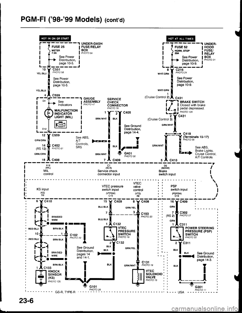
PGM-Fl ('98-'99 Models) (cont'd)
FUSE 2s
See PowerDistribution,
L_J__':n1:'_.:
i-T;;,;,---l HSBE'I nonr. sror : FUSE/I J roA I RELAYI I See Power I BOx
i ts Distribution, ! PHoro2t
L_J__0"n" to'n_..i
UNDER-DASH T-T------'I UNDER-FUSE/RELAY I ' FUSEs2 IHOODtuErER : BOX ! nonn.sror : FUSETr.3A Jp4oro5q I I2oA I RELAY
uauuE sERvtcEASSEMBLY aHidK- lT'! BRAKE swtrcHPHaro4T coNNEcroR ! / I closed wilh brakeP1oro 76 | {_. I pedat depressed.1 Y- -:-'Y .:rnE a \1,. DHOIO 129i 66g"; ilti5Xx+15l'""
I PHoroT6
ll^3j l;i,X|,io'"*".
i ry/,-'Em.dui6 | *";Xf-".'{'*',.."".*,'",-A*f.i.";"'"
Lt*F,--;J^,,
I i**''i
";\&**"**
| li'l|l (scs) pP8nu I
I I'illL. Service check Brake Ii control connector input switch inpul \
i: wEcpressure fiff ii psp : \
lj rslnpur s*[cninput- ii'iiror : i switch inpur : I
fi (6:) '"f'?-) %-' : : FJ:*t : iL------- t-L---J
;tx;
"-'TJ.!.
"oo,
: :[:"': l. -u-.1
i[uE,
i
*"T,!. enroLxl
' -i-----1
i
".''"]rf
_ en*err I
i fi:i
-'-- !
i 'T""t """'"'- !
ilrff:;iJ:rl *:f
See ABS, I
6lt"uo,", F:i
ffi; :i
*.1
I
i ll-i ""^,"." 'fr----1f,il0,3,,
i i ,"l,fF'%%"' i, i-[- t wrne BLU BLK f ll ; ' onN I
i"..*t-T;i;;i ffiff'rul.'l ii Ej'ir1'pi='Et'x'i
I la$ I .*^*"'-" ".*'f ""'^..-.
! i i _:f
*" :
: i-[l ffir* I iii:!:i* >+i
o"n""l
i l-' "'"1 u'* - seeGround I
i
-o-: --1i i l^_^-
'1:
i-<3:"J:qT3"'i
i Hf'.!$*
ll
J
I
lJrlffi"r"",
: l__ j
, : *"* E ;; ---="*L-l
"*fiix+*,"i
i
""[
23-6
Page 1523 of 1681

Headlights (cont'd)
- How the Circuit Works
Low Beam OperationRefer to the Service Manual (Section 23, Electrical)
for specific tests or troubleshooting procedures.
With the headlight switch in HEAD and the dimmer
switch in LO, current flows through the headlight
switch, fuse 21 , tuse 22, and the low beam
filaments to ground, and the low beams come on.
tligh Beam Operation
With the headlight switch in HEAD and the dimmer
switch in Hl, current flows through the headlight
switch, dimmer/passing switch, fuses 4, 5, 21, and
22, and the low and high beam filaments to ground,
and the low and high beams come on.
Current also tlows through the high beam indicator
light to ground. The high beam indicator comes on
to remind the driver that the high beams are on.
Flash operation
The flash feature works with the headlight switch in
OFF, PARK, or HEAD (low beams). When you
move the flash-to-pass switch to ON, current flows
through the switch, fuses 4 and 5, and the high
beam filaments to ground, and the high beams
flash. The high beam indicator also flashes during
the flash oDeration. The flash function has no effect
it the high beams are already on.
Daytime Running Lights Day Operation
When you turn the ignition to ON (ll) with the
parking brake released, the daytime running lights
control unit supplies battery voltage at the
WHT/RED wire. This voltage is applied to the high
beam headlights through the daytime running lights
resistor. Each high beam headlight receives less
than battery voltage causing them to come on al
reduced brightness.
lf the parking brake is set, a ground signal is applied
to the daytime running lights control unit at the
RED/GRN wire. It the parking brake is set when you
first turn the ignition switch to ON (ll), the high beam
headlights will remain off until you release the
parking brake. Once the high beam headlights are
in day mode, setting the parking brake will not
cause the headlights to turn off . When low or high
beam operation is requested, baftery voltage trom
the headlight switch is applied to the daytime
running light control unit via the RED/vVHT wire.
The daytime running light control unit then
discontinues the daytime running light mode.
1 10-10
Page 1659 of 1681

:/
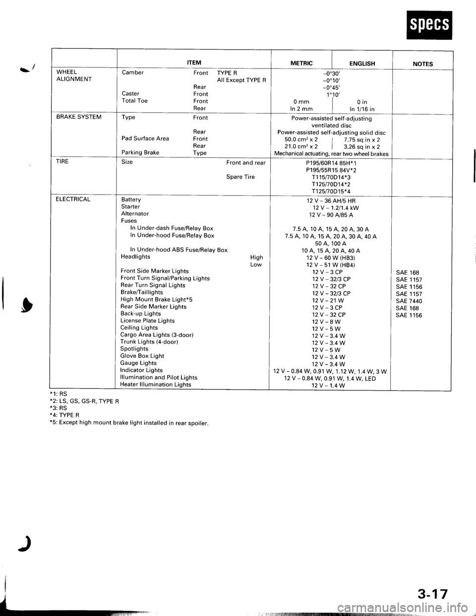
*1: RS*2: LS, GS, GS.R, TYPE R*3: RS+4: TYPE R*5: Except high mount brake light installed in rear spoirer.
ITEMMETRICENGLISHNOTES
WHEELALIGNMENTCamber Front TYPE RAll Except ryPE RRearCaster FrontTotal Toe FrontRear
-0"30'_0"10,_0"45'
1"10'omm I oinIn 2 mm I In 1/16 inBRAKE SYSTEMType Front
RearPad Surface Area FrontRearParking Brake Type
Power-assisted self-adjustingventilated discPower-assisted self-adlusting sol id disc50.0 cm2 x 2 | 7.75 sq in x 221.0 cm, x 2 | a.ZO sq in x 2Mechanical actuating, rear two wheel brakesTIRESize Front and rear
Spare Tire
P195/60R14 85H*1P195/55R15 84V*2T115t0D14*3T125/70D14*2T125n0D15*4
ELECTRICALBatteryStarterAlternatorFusesIn Under-dash Fuse/Relay BoxIn Under-hood Fuse/Relay Box
In Under-hood ABS Fuse/Relay BoxHeadlights
Front Side Marker LightsFront Turn Signal/Parking LightsRear Turn Signal LightsBrake/TaillightsHigh Mount Brake Light*5Rear Side Marker LightsBack-up LightsLicense Plate LightsCeiling LightsCargo Area Lights (3-door)Trunk Lights (4-door)SpotlightsGlove Box LightGauge LightsIndicator Lightslllumination and Pilot LightsHeater lllumination Lights
HighLow
12 V _ 36 AH/5 HR12V -1.2/'t.4kW
12V-90A/85A
7.5 A, 10 A, 15 A, 20 A, 30 A7.5 A. 10 A, 15 A, 20 A, 30 A, 40 A50A,100A10A,15A,20A,40A12V-60W(H83)12V -51 W (HB4)12V-3CP12V _3213 CP12V _32 CP12V-3213CP't2v -21 W12 V - 3 CP12V -32CP
12V_8W12V-5W12V-3.4W12V-3.4W12V_5W12V-3.4W12V-3.4W12 V - 0.84 W, 0.91 W, 1.12W, 1.4W, 3 W12 V - 0.84 W, 0.91 W, 1.4 W, LED12V-1.4W
SAE 168SAE 1157SAE 1156SAE 1157SAE 7440SAE 168SAE 1156
3-17
Page:
< prev 1-8 9-16 17-24