Page 1398 of 1681

I
I
I
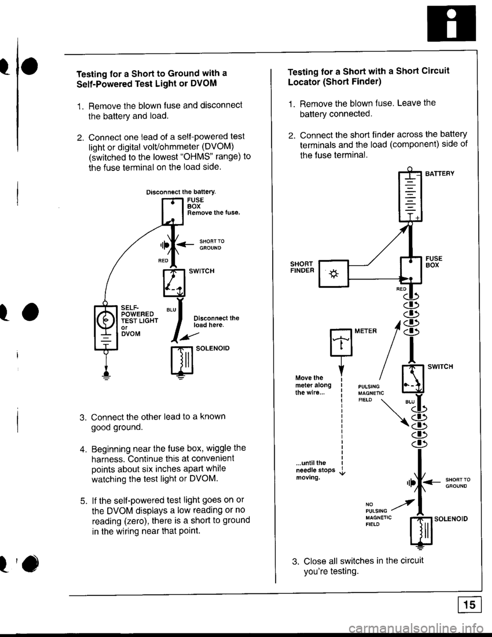
Testing for a Short to Ground with a
Self-Powered Test Light or DVOM
1. Remove the blown fuse and disconnect
the battery and load.
2. Connect one lead of a self-powered test
light or digital volvohmmeter (DVOM)
(switched to the lowest "OHMS' range) to
the fuse terminal on the load side.
Disconnect the battery
FUSEBOXRemove the tuse,
<- li9T:oGFOUND
Disconnect theload here.
.aa'
t-t SoLENOTO
Connect the other lead to a known
good ground.
Beginning near the fuse box, wiggle the
harness. Continue this at convenient
points about six inches apart while
watching the test light or DVOM.
lf the self-powered test light goes on or
the DVOM displays a low reading or no
reading (zero), there is a short to ground
in the wiring near that Point.
SELF-POWEREDTEST LIGHTorDVOM
A
5.
Testing lor a Short with a Short Circuit
Locator (Short Finder)
1. Remove the blown fuse. Leave the
battery connected.
2. Connect the short finder across the battery
terminals and the load (component) side of
the Juse terminal.
BATTERY
SHORTFINDER
...untiltheneedle stopsmoving.
3. Close all switches in the circuit
you're testing.
MErER 18
n
iH"#/ El'*"""'*"
"'-LL
\8
I
"rf--:*ll;"
il,",r. y'l
:[:J"'"
s;.o"*o'o
Page 1500 of 1681

Gauges (cont'd)
- How the Circuit Works
When the ignition switch is in ON (ll) or START (lll),
battery voltage is supplied through fuse 25 to the
gauges in the gauge assembly.
Speedometer and Odometer
The odometer and speedometer drive circuits
receive pulses lrom the vehicle speed sensor
(VSS). The pulse rate increases as the car
accelerates. The frequency and duration of these
input pulses are measured and displayed by the
speedometer, odometer and tripmeter.
Tachometer ('98-'99 Models)
The tachometer drive circuit receives oulses from
the ignition control module (lCM) in the distributor
assembly. The solid-state tachometer then displays
these pulses as engine speed. For each 200 pulses
per minute from the ignition control module (lCM),
the tachometer displays 100 RPM.
Tachometer ('00 Model)
The tachometer drive circuit receives pulses f rom
the PCM or ECM. The solid-state tachometer then
displays these pulses as engine speed. For each
200 oulses oer minute trom the PCM or ECM the
tachometer displays 1 00 RPM.
Engine Coolant Temperature Gauge and Fuel
Gauge
The engine coolant temperature gauge has two
intersecting coils wound around a permanent
magnet rotor. Voltage applied to the coils, through
fuse 25, generates a magnetic field. The magnetic
field, controlled by the engine coolant temperature
gauge sending unit, causes the rotor to rotate and
the gauge needle to move. As the resistance in the
sending unit varies, current through the gauge coils
changes. The gauge needle moves toward the coil
with the strongest magnetic tield. The fuel gauge
works the same way.
The engine coolant temperature gauge sending
unit's resistance varies from about 137 ohms at low
engine temperature to between 30-46 ohms at high
temperature (radiator fan running).
The fuel gauge sending unit's resistance varies from
about 2-5 ohms at full, to about 110 ohms at empty.
When you turn the ignition switch to LOCK (0), the
gauge remains at the last reading until you turn lhe
ignition switch to ON (ll) or START (lll) again.
Refer to the Service Manual (Section 23, Electrical)
for specific tests or troubleshooting procedures.
81'2
Page 1664 of 1681

Lubrication Points
\_For the details of lubrication points and type of lubricants to be applied, refer to the illustrated index and various work pro-
cedures (such as Assembly/Reassembly, Replacement, Overhaul, Installation, etc.) contained in each section.
*1: Always use Genuine Honda Manual Transmission Fluid (MTF). Using motor oil can cause stiffer shifting because it
does not contain the proper additives.*2: Always use Honda ATF-Z1 (ATF). Using a non-Honda ATF can affect shift quality.*3: Always use Genuine Honda DOT 3 Brake Fluid. Using a non-Honda brake fluid can cause corrosion and decrease thelife of the system.*4: Always use Genuine Honda Power Steering Fluid. Using any other type of power steering fluid or automatic transmis-sion fluid can cause increase wear and poor steering in cold weather.i
4-2
5 ffi
No.LUBRICATION POINTSLUBRICANT
1EngineAPI Service Grade: Use SJ "Energy Conserving" grade oil.The oil container may also display the API Certificationmark shown below. Make sure it says "For GasolineEngines."
SAE Viscosity: See chart below.
2Tra.nsmissionManualHonda Genuine MTF*2
AutomaticHonda ATF -21 (ATFY2
3Brake line (lncludes Anti-lock brake line)Genuine Honda DOT3 Brake Fluid*3
4Clutch lineGenuine Honda DOT3 Brake Fluid*3
5Power steering gearboxSteering grease P/N 08733 - 8070E
6Release fork (Manual transmission)Super High Temp Urea Grease (P/N 08798 - 9002)
.J
Throttle wire end (Dashboard lower panel hole)
Cruise control actuator wire end(Dashboard lower panel hole)
Silicone grease
q
10
11
12
13
14
Throttle cable end (Throttle link)
Cruise control actuator cable end (Actuator link)Brake master cylinder pushrod
Clutch master cylinder pushrod
Battery terminalsFuel fill lid
Multi-purpose grease
tc
16
17
18
Engine hood hinges and engine hood latchHatch hinges and latch or trunk hinges and latch
Door hinges, upper and lower
Door open detent
Honda White Lithium Grease
19Rear brake calipersSilicone grease
20Power steering systemGenuine Honda Power Steering Fluid*a
21Air conditioning compressorRefrigerant oil ND-olL8 (P/N38897 - PR7 - A01AH or
38899-PR7-A01)(For Refrigerant: HFC-1 34a (R-1 34a))
API SERVICE TABELAPI CERTIFICATION SEAT
ZU30
Recommended engine oilEngine oil viscosity forambient temperature ranges
Page:
< prev 1-8 9-16 17-24