Page 1156 of 1681
)
)
Charging System
Component Locationlndex
CHARGING SYSTEM LIGHT(ln the gauge assembly)Test, pages 23-102,103Bulb Locations, page 23-122
UNDER-HOOD FUSE/RELAY BOX(USA: HAS bUiIt-iN ELECTRICALLOAD DETECTOR (ELD) UNIT}Troubleshooting of ELD, secrion 11
BATTERYTest,
ALTERNATOR BELTInsp€ction and Adiustment, page 23_115ALTERNATORTroubleshooting, page 23'102Alternator/FegulatorTosl, pages 23-105,'106Replacement, page 107Overhaul, page 23-108
23-99
.t-
Page 1157 of 1681
a
Charging System
Circuit Diagram
INTEGRATEOCONTROL UNIT
V
II
ECM
V
II
UNDER.HOOD FUSE/RELAY BOX
No41 (1tl0A) /^ N0.42 (40A)
FIETDWINOING
WHT/8LU
L
GFN/REO
I
I
I
I-t
-"
ALTERNATOR
BLK/YEL
23-100
I-
Page 1159 of 1681

Charging System
Troubleshooting
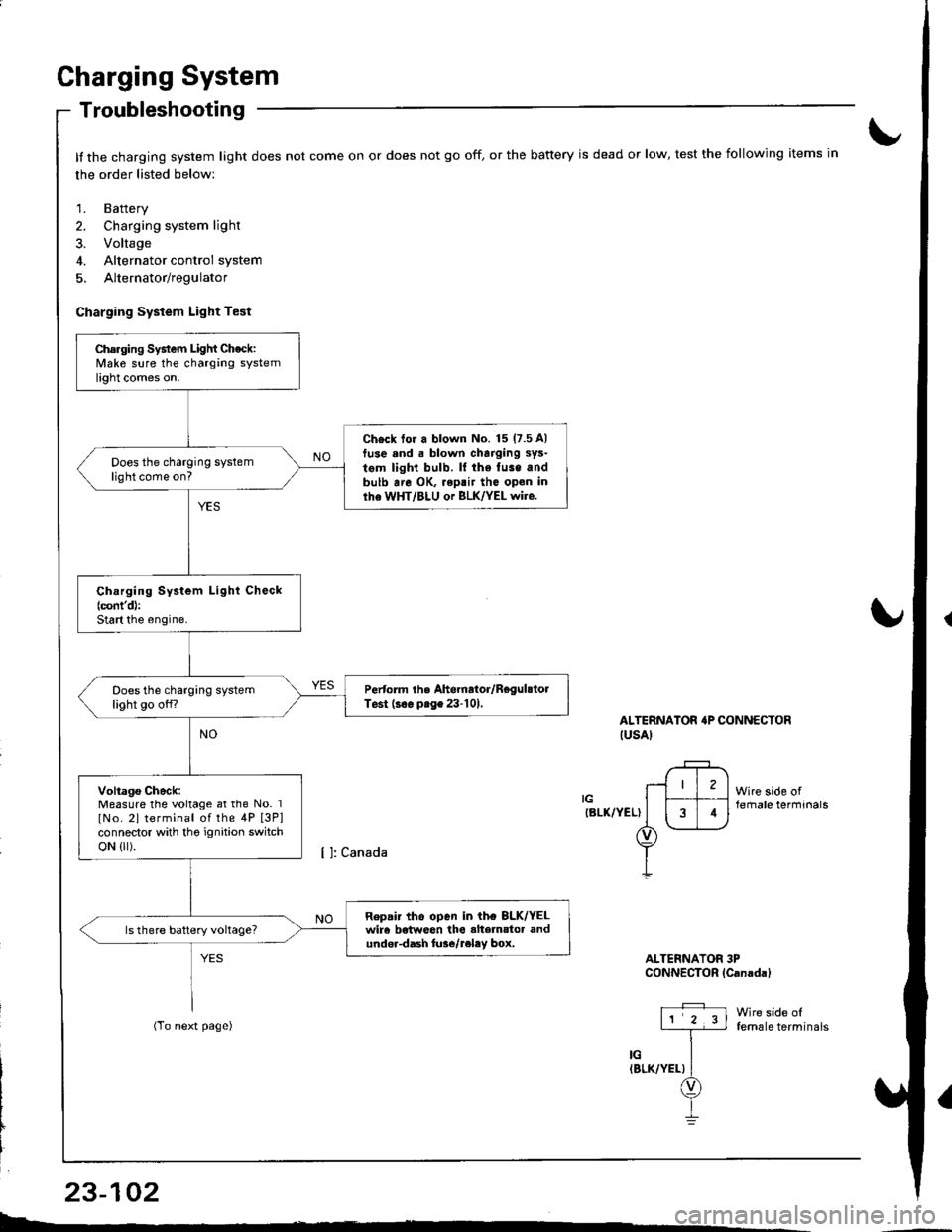
It the charging system light does not come on or does not go off, or the battery is dead or low, test the following items in
the order listed below:
1. Battery
2. Charging system light
3. Voltage
4. Alternator control system
5. Alternator/regulator
Charging System Light Test
ALTERNATOR'P CONNECTORIUSAI
IGIBLK/YEL)
Wire side offemale terminals
Wire side offemale terminals
ALTERNATOR 3PCONNECTOR lCanadal
Charging System Light Check:Make sure the charging systemlight comes on.
Ch€ck tor a blown No. 15 (7.5 A)
tuse and . blown charging sys-
tem light bulb. ll the fuse andbulb are OK, .eptir tho open inlhe WHT/BLU or BLK/YEL wire.
Does the charging systemlight come on?
Ch.rging System Light Check(cont'd):
Start the engine.
Pertorm the Ahernator/RegulstolTest (s€. prge 23-101,Does the charging systemlight go off?
Voltago Check:Measure the voltage at the No. 1
lNo. 2l terminal of the 4P [3P]connector with tho ignition switchoN {lr).
Repair tho open in ih€ 8LK/YELwir6 betweon the alte]nator andundor-dash lure/reley box.
I4
L-*
23-102
Page 1160 of 1681
{From previous page}
Repai. ths open in tho WHT/ALUor BLK/YEL wir€.Does the charging systemlight come on?
Chock tor a sho.l in the L cir-cuit lcont'd):Disconnect the No.3 terminal ofthe 4P [3Pl connector from theground.
Does the charging systemlight go offi
Repair the shon to ground in thoWHT/BLU wiro.
{
t
Check for an opon in lhe L cir-cuit:1. Turn the ignition switch OFF.2. Disconnect the 4P connectorfrom the alternator.3. Ground the No. 3 terminal ofthe 4P [3Plconnector.4. Turn the ignition switch ON (ll).
ALTERNATOB irP CONNECTOR
ALTERNATOR 3PCONNECTOR {Canadal
11 2 3l
,l
iin"vr.rr\
Wire side oftemale t€rminals
[ ]: Canada
LIWHT/BLUI
LIWHT/BLU)
Wire side offemale terminals
)
23-103
4
--
Page 1162 of 1681

{
t
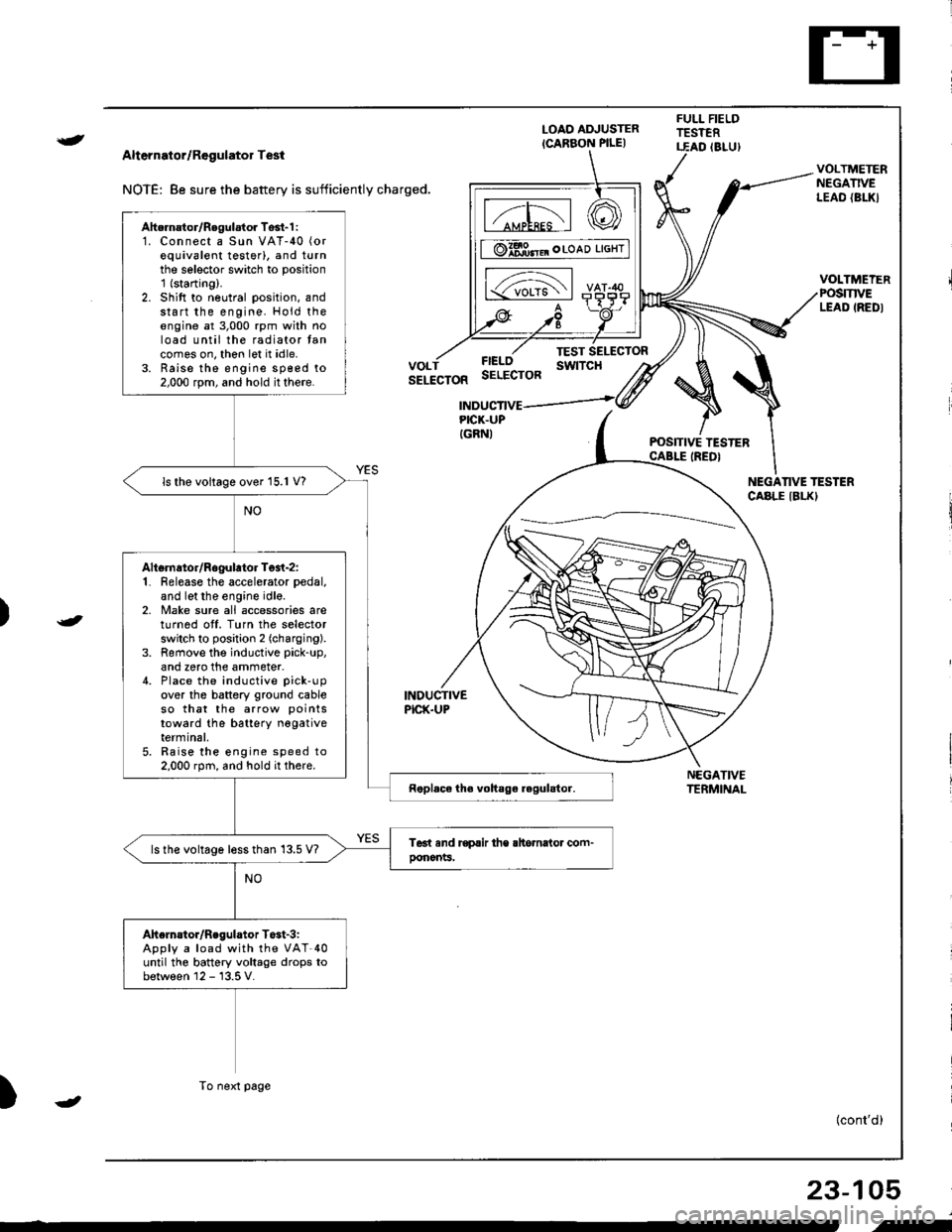
Alternator/Regulator Test
NOTE: 8e sure the battery is sufficiently charged.
LOAO ADJUSTER
ICARBON PILE)
FULL FIELDTESTERT.EAD (8LU)
POSITIVE TESTERCABLE IREDI
NEGATIVETERMINAL
VOLTMETERNEGATIVELEAO {BL|(}
VOLTMEIERPOSmVELEAD IREDI
FIELOSELECTOR
TEST SELECTORswtTcHVOLTSELECTOR
INDUCTIVEPICK.UP
INDUCTIVEPICK.UPIGRNI
NEGANVE TESTERCABLE IBLKI
)
)
{cont'd)
23-105
Ahernator/Regulator Tosl-1 :1. Connect a Sun VAT-40 (or
equivalent testerl, and turnthe selector switch to position'1 (starting).
2. Shift to neutral position, andstart the engine. Hold theengine at 3,000 rpm with noload until the radiator tancomes on, thon let it idle.3. Raise the engine sp€ed to2,000 rpm, and hold it there.
ls the voltage over 15.1 V?
Altsrnator/Rogulator Test-z:1. Release the accelerator pedal,
and let the engine idle.2, Make sure all accessories areturnod off. Turn the selectorswitch to position 2 (charging).
3. Remove the inductive pick-up,
and zero the ammeter.4. Place the inductive pick-up
over the battery ground cableso that the arrow points
toward the batterY negativeterminal,5. Raise the engine speed to2.000 rpm, and hold it there.
ls the voltage less than 13.5 V?
Ahelnstor/Regulator T$t-3iApply a load with the VAT-40until the battery voltage drops tobetween 12 - 13.5 V.
To next page
-
i-
Page 1163 of 1681
From previol.rs page
The charging swtem is OK.lsthe amperage 70 A or more?
Alternator/Regulator Test-4:With the engine speed still at2,000 rpm, Iull-Iield the alternator.
Charging System
Troubleshooting (cont'dl
CAUTION: Th6 voltago will rise quickly when the ahernator is ful!fieldcd. Do not .llowth6 voltag€ to €xc6ed 18 V; it may damage tho ol6drical system.
NOTE: Attach a probe to the VAT'40 full field test lead, and insert the probe into the lullfield access hole at the back of the alternator. Switch the field selector to the "A {Ground}"position momentarily, and check the amperage reading.
REGULATOB(Located inside
FULL FIELOACCESS HOLE
END COVEB
END COVER
FULL FIELDACCESS HOLE
L^
23-106
Page 1165 of 1681
Charging System
Alternator Overhaul
CAUTION: Do not remove the pulley unless the tront
bearing needs replacement.
To loosen the pulley locknut, use 10 mm and 22 mm
wrenches. lf necessary, use an impact wrench.
DENSO:
PULLEY LOCKNUT1'11 N.ft (11.3 kgf.m,82 lbt.ft)
FRONT BEARING
STATOR/DRIVE ENDHOUSINGOENSO:Test, page 23-1'10MITSUBISHIITest, page 23-112
PULLEY
CAUTION: Do not get grease
or oil on the slip rings.
BRUSH HOLDERINSULATOR
offiEND COVER
k-"o*"... ".,"' BRACKET
23-108
L_�
ROTOR
PULLEY
10 mm 8OX WRENCH
BEARING
Page 1167 of 1681
Charging System
Rotor Slip Ring Test
DENSO:'l . Check that there is continuity between the slip rings.
ROTOR SHAFT
Check that there is no continuity between the slip
rings and the rotor or rotor shaft.
lf the rotor fails either continuity check, replace the
alternator.
Stator Test
1 . Check that there is continuity between each pair ot
leads.
Check that there is no continuity between each lead
and the coil core.
lf the coil lails either continuity check, replace the
alternator.
2.
3.
2.
3.
23-110
cotl coRE
b-.