Page 609 of 1681
Differential (B18C1 engine)
lllustrated Index
J
J
NOTE: lI parts marked with an asterisk {*)were replaced, the tapered roller bearing preload must be adjusted (see page
15 15).
*CLUTCH HOUSING
OIL SEAL Replace.Removal, page 15 13Installation, page 15 17
*THRUST SHIMT. 2.5 mm {0.098 in)
*TAPERED ROLLER BEARINGlnsDect for wear and ooeration.Replacement, page 1 5-13
*BEARING OUTER RACEInspect for wear and damage.Replacemenl, page 15 14
10 x 1.0 mm
*DIFFERNTIAL CARRIERInspection, page 15-12
101 N.m {'10.3 kgf.m, 74.5 lbf.It)Le{t hand threads
*TAPERED ROLLER BEARINGInspect tor wear and operation.Replacement, page 15 13FINAL DRIVEN GEARInspect tor wear and damage. -----------r'
Repfacement. page 15-1 2
}BEARING OUTER RACE
*79.5 mm SHIMSelection, page 15 16
*TRANSMISSION HOUSING
OIL SEAL Replace.Removal, page 15-13Installation, page 1 5-17
.la
15-1 1
Page 611 of 1681
Tapered Roller Bearing ReplacementoilSealRemoval
1.
2.
Remove the difterential assembly.
Remove the oil seal lrom the transmission housing.
TRANSMISSION HOUSING
3. Remove the oil seal irom the clutch housino.
NOTE:
a The tapered roller bearing and bearing outer race
should be replaced as a set.
a Inspect and adjust the tapered roller bearing preload
whenever the tapered roller bearing is replaced.
a Check the tapered roller bearings for wear and rough
rotation. lI tapered roller bearings are OK, removal is
not necessary.
1. Remove the tapered roller bearings using a bearing
puller and bearing separator as shown.
BEARINGPULLER(Commercially
available)
BEARINGSEPARATOR(Commercially
available)
Install new tapered roller bearings using the special
tool as shown.
NOTE: Drive the tapered roller bearings on until they
bottom against the dillerential carrier.
DRIVER, 40 mm LD.07746 -OO30100
j
1 5-13
Page 1051 of 1681
J
Glutch Overhaul
1. Remove the center bolt while holding the pressure
plate,
A/C CLUTCH HOLDER
lCommorcially available)Robinair: P/N 1020,1
Kent-Moor6: P/N J37872
2.
CENTER BOLT13.2 N.m {1.35 kgf m,9 76lbtft)
IRemove the pressure plate and shim(s) taking
not to lose the shim(s).
sHtM(sl
[4
3. Remove the snap ring B with a snap ring pliers,
then remove the pulley.
NOTE:
o Be careful not to damage the pulley and com-
pressor during removal/installation.
. Once the snap ring B is removed, replace it with
a new one.
(cont'd)
I
/ T-\vr= ...--.-
-ffitll---.\lr l,
\-l I .v
22-33
Page 1052 of 1681

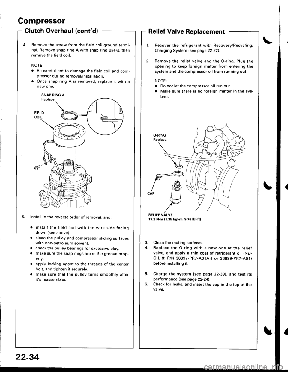
Compressor
a
a
Clutch Overhaul (cont'dl
Remove the screw from the field coil ground termi,
nal. Remove snap ring A with snap ring pliers, then
remove the field coil.
. Be careful not to damage the field coil and com-presso. during removal/installation.
. Once snap ring A is removed, replace it with a
SNAP RING AReplace.
5. Install in the reverse order of removal, andl
install the field coil with the wire side facing
down (see above).
clean the pulley and compressor sliding surfaceswith non-petroleum solvent.
check the pulley bearings for excessive play.
make sure the snap rings are in the groove prop-
efly.
apply locking agent to the threads of the center
bolt, and tighten it securely.
make sure that the pulley turns smoothly after
it's reassembled.
Relief Valve Replacement
Recover the refrigerant with Recovery/Recycling/
Charging System lsee page 22-221.
Remove the relief valve and the O-ring. Plug the
opening to keep foreign matter from entering the
system and the compressor oil from running out,
NOTE:
. Do not let the compressor oil run out.
. Make sure there is no foreign matter in the sys-
tem.
RELIEF VALVE13.2 N.m (1.35 kgf.m,9.76lbtft)
3. Clean the mating surfaces.
4. Replace the O-ring with a new one at the relief
valve, and apply a thin coat of refrigerant oil (ND-
OIL 8: P/N 38897-PR7-A01AH or 38899-PR7-A01)
before installing it.
5. Charge the system (see page 22-39), and test itsperformance (see page 22-241.
6. Check for leaks, and insert the cap in the top of the
FIELD
t\I lu
B _t_:---\-lr
\,/
22-34
Page:
< prev 1-8 9-16 17-24