Page 1478 of 1681
From A onlacrng page.
v^,..^-^ i"'""14
"";+,eru,neo I
z A ctuo
FUSE 17llEAtES ,i/C iELAYt.lta
UNDER-OASHFUSE/RELAYBOXPHO|O 58Sg€ PowarDistributlon,
A/C PRESSUREswrTcHLow: Open below 200 kPa (28 psi).High: Open above 3100 kPa (460 Psi).
Dislributlon,page 10€."a*,tra ll
".,. ifrF'fl%"
A,/CTHERMOSTATOtf below3'C (37"F).
THERMISTOR
See AirDelivery
BLKTYEL Se€ PoweT
4 il"Stt",j'::'
,i/c oNIt{DICATOR
A,/CswrcH
I CoNTROL
iPANEL
rO
:tI
a
il
au,vel N
t
__':rc684
1YC1s4"rr*1r ! ^...
".,r*", I i'abi6 o
ro J cco+;r't::
2 Y C676BLU]REO II
".",1.t"fr 9,9%,,
rrl--.
62-1
Page 1479 of 1681

A/C Gompressor Controls (conrd)
- How the Circuit Works
Battery voltage is supplied through fuse 56 to the
A,/C compressor clutch relay contacts at all times.
With the ignition switch in ON (ll), voltage is applied
to the coil of the A,/C compressor clutch relay
through fuse 17. When you push the A,/C switch
ON, and the heater fan switch is in posation 1, 2, 3,
or 4, a "ground" input is provided to the engine or
powertrain control module (ECM or PCM) through
the A,/C thermostat and the A,/C pressure switch.
The A,/C compressor clutch relay is grounded by the
engine or powertrain control module (ECM or PCM).
When energized, the A,/C compressor clutch relay
allows battery voltage to turn on the A,/C
comDressor clutch,
The A,/C ON indicator light comes on when the A"/C
system is requested.
A,/C Thermostat
The A,/C thermostat is located on the evaoorator
housing. The AJC thermostat turns off the A,/C
compressor clutch if the temperature at the
evaporator goes below 3'C (37'F). This prevents
condensation from freezing on the evaporator fins
and blocking the air delivery into the passenger
compartment. The blower motor will keep running
when the sensor lurns off the compressor.
A,/C Pressure Switch
The A,/C pressure switch is located in the condenser
outlet line where refrigerant is in a high
temperature/high pressure liquid state. The switch
will sense abnormally high or low pressure, and
open the circuit. This removes ground, and the
compressor will stop running.
Refer to the Service Manual (Section 22,
Air Conditioning) for specific tests or
troubleshooting procedures.
62-2
Page 1480 of 1681
Fans
- with
|------
See PowerDistribution,page 1G6.
;;;----13X3,5"
l,fP"[r s"" eo'""t
A/C -
E@
UNDER.HOODFUSE/RELAYBOXDistribution,
FUSE 56(coxoEr{sE8 faN}FUSE 57COOLING
204
FUSE/RELAY
2
(Not
I
I
I
I
IL
I Y C439sucrel ll PHoro"62rrr.
orl
*T'.I.
:-gg]gi Ji,'oio,,,
Seg PowerDistribution,page 10.6.c216y":':---______i
See PowerDbtribution,page lG1.
c2'16 1
BLKBEO
' POWERTRAIN ,
: or ENGINE, CONTROL ::,::A ,. ' MODULE ;(PCM or ECM) ,' PHOIA 77 (9A 99 |' PHofa 14a $q :!---- usA.----
COI{DENSERFANRELAYPHOTO 23
RADIATORFANRELAYHlofa 22
c215-----J
* '98199 [,4odels
cltl8LU/BLK
c9{t6
c206
c206
ffi-
".",".t"f
"oo' 6
i
v
To Splice onfacing page
c151
c155
BLU/BIK
BLU/ALK
CONDENSERFANMOTOR
RADIATORFANMOTOR
RADIATORFAN SWITCHClosed above93"C (200"F).
".:r
"'''
I see c,ornoarr< Distribution,
".,.f
','"i.
-lr:;--: PHafo 28
c155PHOTA 9
See GroundDistribution,page 14-2
Y
I
63
I. G151
Page 1481 of 1681
From IVC Diodeon facing page.
v
".r,".o ! ".u,".o
1 YCls4 '- --
"t"*1t ,I, ^..,
-t'I:::'
ri'fft_____:_
POWERTRAIN
! *'"P* ! 3b'nli?3'-"oou'.I rAcs' I {PCM or ECM}
| ,S1, I iuorozz $a.ssiLJ:LJ PHora 14a too)IIEATES IJC RELAY?54
UNDER.DASHFUSE/RELAYBOXPHO|O 58
r 5) Y (C409 *)
27 n c408
See PowerDistribution,page 10-6.a
";;;ic151
c154
* '98'�99 Models
I'lC PRESSURESWITCHLow: Open below 200 kPa (28 Psi).High: Open above 3100 kPa (460 Psi).
.4
See Po' erDistribution,page 106,
See PoworDbtribution,page 1G6.
A/CTHERMOSTATOfl below3'c (37"F).
THERMISTOR
S€e AirDelivery
"a*a, i
*,*rfrs,*lt-
a
BTK,"VEI i
9:1L"" t
::;1".,.
I Dimmlng t
-.I HEATER,J--- I cONrR(CONTROL
Circult
r,/c oNINDICATOR
".1r "ur'
I 8:8ffiTo
o'"u''"''n'
*!r".-
F--9*l:93----r HEATER
!iIA{. lSiii,"'.
L:5-l--i
63-1
Page 1482 of 1681

Fans
- Without A/C
UNDER-HOODFUSE/RELAYBOX
r--------UNDER-DASHFUSE/RELAYBOXFUSE 57cooLrfic FAx2oa
a4 Distribution,
_ ' Cg(F
ll Pase 106'BLK,YEL I
. A """?t'3"---------JI Soe Powgri------{' Distribution,
I page 10-6./\-_--_--
'I
GBN
RADIATORFANRELAYP|1OTO 22
: l__
ru::
.i
-d*"^
ffil u
(Not Used)---?f;---------==:
I (Nor Used)BLUT'EL
f
"
f,r;.;
.l "oo, I
'[TliiF:,- il
"'*,'
-r-I I "-'" I
i*'Er t: 11,c402 i
*-
:lI' Btu'RED I er-uraeo I
i 3__J
:ilt; ".r,".o I
i ,, I "oo.: (. s) x (c4oe -)
l---rNTl:,oll,ffIE '"
: Used) I CoNTROL' I MODULE
: | (PcM or EcM). I PHA|O 77 (98 99):_----- PHOTO 140 taAl.,
)8 '99 Models
(Not Used)
?i-------=
,.'! rN(
. I .oo,PF.IA/c
Lf l"r,i"r,B%
ItlI .t. l
.:x
*::_,"."
24
t_
l'*
c301
PHOTO36
t9
GBN
See GroundDistribution,page 14-2.
I
I
_l
, r27) A C408
i r-;--, I iiiir o
; I FAN. I control;t, L----
I'irl RAOIATORI t I FANswtrcH
l{-cl 9J3?39,"-"e e3 c (2oo F)
1 Y c11r
"*l
Orr< See GroundI Distribution,BLK
L/-4
eaee 14.
1FJ�::.,"
usA ---.
* '98
._____.-'.1!;;6i-
PHO|O 4
63-2
Page 1483 of 1681

Fans (cont'd)
- How the Gircuit Works
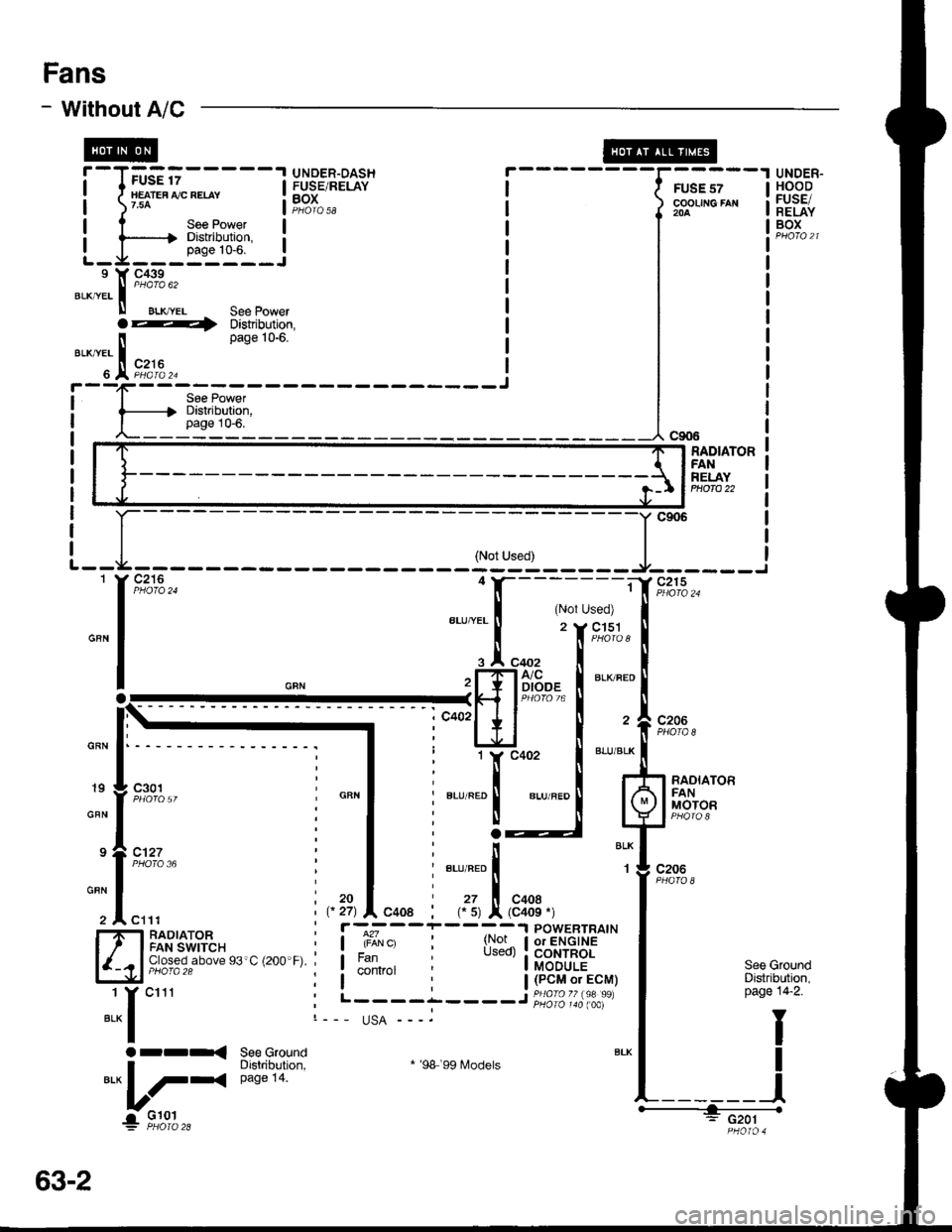
When the ignition switch is in ON (ll), voltage is
applied to the coils of the radiator fan relay and the
condenser fan relay (with A,/C) through fuse 17.
Whenever a ground is provided to the radiator fan
relay and condenser fan relay, the relays are
energized, turning on the radiator fan motor and
condenser fan motor. The relays can be grounded
by the radiator fan switch, engine or powertrain
control module (ECM or PCM) (USA), or the A,/C
and heater lan switches via the A'lC pressure switch
and the A,/C lhermostat.
A,/C Thermostat
The A,/C thermostat is located on the evaporator
housing. The A/C thermostat turns oft the A/C
compressor clutch it the temperature at the
evaporator goes below 3'C (37"F). This prevents
condensalion from freezing on the evaporator fins
and blocking the air delivery into the passenger
compartment. lt the temperature goes below 3'C
(37'F) turning off the A"/C thermostat, and the
BLU/RED wire at the A,/C diode was the only wire
providing ground to the condenser and radiator
fan relays (A,/C switch on, heater fans switch on,
radiator fan switch open, and ECM or PCM fan
controi output not grounded), the relay will
deenergize removing voltage from the condenser
and radiator fan motors causing them to stop
running.
A,/C Pressure Switch
The AJC oressure switch is located in the condenser
outlet line where refrigerant is in a high
temperature/high pressure liquid state. The A,/C
switch turns off the A,/C compressor clutch if it
senses abnormally high or low pressure. lf the A'lC
pressure switch opens, and the BLU/RED wire at
the A/C diode was the only wire providing ground
to the condenser and radiator fan relays (L/C switch
on, heater fans switch on, radiator lan switch open'
and ECM or PCM fan control output not grounded),
the relay will deenergize removing voltage from the
condenser and radiator fan motors causing them to
stop running.
A./C Diode
This diode orevents the radiator fan switch f rom
grounding the "A'lC ON" input to the engine or
powertrain control module (ECM or PCM).
Refer to the Service Manual (Section 23, Electrical)
for specific tests or troubleshooting procedures.
63-3
Page 1484 of 1681
H"ar ffndow Defogger
---.I UNDER.
i-I,;.;;lH8B'J i
illk.**"llieF iL-Ja---J PEoro 21 L
I DASH
i FUSE/I RELAYI Box
FUSE 16NEAR DEFROSI€B NEIAY7.54
__J PHO|O sA
[._
See Dashand ConsoleLights
Y
"ao,"a" I
--g-,1 cser
c2172
ALK/BLU
'T 9#.'9,,BTruBLU
i
"r'u"au !
@cREARwtNDowDEFOGGERswtTcH
See PowerDistribution,pago 1G6.
c422
UNDER-DASHFUSE/RELAYBOX
S€e GroundDistribution,page 14-5.
:ffilfi$Eijc914Hatchback t1
-----l".* o"nf, L----
f ;fl,:" "onn"",o., -",
I not be presenl in allcars.)
BL|(GRN
I
I
I "u.o
l-lFl REARI .5 | WTNDOW
lll
oEFoGGER
,.^f "tt'
"";',u'," i il{:{'}Fl
l'*'**T.lJ: PHoTo 102
c753
1 REARI WINDOW
I DEFOGGERIJ BLIIGRNc771
1
BLK/GFN
rII
G?7.1 L
".of,or"i:
BU( ltGFNA c516
'." ! 1]ll'.llGRN ll pre6e
2 J C525BL|! ll P,lorc
neof czss
msi
lllo'Y c771
BLK
BLK
cs16(ln-line connectorlmay not bepresent in allcars.)
"..1
t
REARwtNDow
swlTcHLIGT'Toila_
ONINDICA.TOR
ry$:F*
::";,=.4
-
: :
-L[; - -
T
- - - - -
I
iiffit]lffi**'
BLKBLU
64
Page 1486 of 1681
Integrated Control Unit
see Rear @Window See Wipef/Washer |-'l----
, See Ground' Distribution,
: pase 14-5.
c439
\
\
I
I
t
I
I
WHT/BLU
c438
YEUREO
'r9,x3
*t
Y
SeeCharoinoSyste'm '
--.-,
See Wiper^Vasher
See EngineOil PressureIndicatorLight
rr{See GroundDishibution,page 14-5.
Y
v---!G401
Window See Wioef/Washer f -'l-- - -'l UNDER-HOODDefogser ,-- | I rUS: +e IFUSE/RELAY
I I I llg:-i***'
1'11f ;'.il::ll ^-.wlhcombined utr?i;,'",,
I I I :,8:[il; * o"' ,n", ",o I
!!!i.t@..!.,*,*..
i
-T--
T-[-- :-;:=::::::{----1-- - - - - - - - -
7'
illli{ry;a';:i {iii:*l i
i, tr---I".!,.*, i, Ljiri'dt'l-t{-:--h i:tf{#;r {
il
L-
See Rear
Defogger
FUSE 26 ,
FFAWASiIEB ' See power
' page 10-5. 6
RearWindowDefoggerTimerCircult
IntermftentWiper RelayCircult
Englns OilPrgssureIndicatolFlasherClrcuit
70
!..