Page 670 of 1681

Rack Guide AdjustmentFluid Replacement
Check the reservoir at regular intervals, and add fluid as
neceSsary.
CAUTION: Use only Genuine Honda Powel Ste€ring
Fluid-V. Using other fluids such as ATF or othor manu-
laclurer's power ste€ring fluid will damag€ the systom.
SYSTEM CAPACIW:
B18Gl ongine:
1.06lit€r (1.12 US. qt,0.93 lmp.qt)
Excopt 8l8Cl ongino:
1.0 lher (r.06 US. qt.0.88 imp.qtl
at disa$ombly
RESERVOIR CAPACITY:
0.,0 liter {0.42 US. qt, 0.35 lmp.qt}
LEVEL LINE
LEVEL LINE
Raise the reservoir and disconnect the return hose
that goes to the oil cooler.
Connect a hose of suitable diameter to the discon-
nected return hose and put the hose end in a suit-
able container.
CAUTION: Take care not to spill thq fluid on lhe
body and parts. Wipe off any spilled fluid al onc€.
Start the engine. let it run at idle, and turn the steer-
ing wheel from lock-to-lock several times. When
fluid stops running out of the hose, shut off the
engine. Discard the fluid.
2.
RETURN HOSE{From the oilcooler)
4. Reinstallthe return hose on the reservoir.
5. Fill the reservoir to the uDDer level line.
6. Start the engine and run it at fast idle, then turn the
steering from lock-to-lock several times to bleed air
from the system,
7. Recheck the fluid level and add some it necessary.
CAUTION: Do not lill the reservoir boyond thc
upper level line.
J.
4.
NOTE: Perform rack guide adjustment with the wheels
in the straight ahead position.
1. Loosen the rack guide screw locknut with the spe-
cialtool, then loosen the rack guide screw.
Tighten the rack guide screw until it compresses the
spring and seats against the rack guide, then loosen
it.
Retighten ihe rack guide screw to 3.9 N.m (0.4
kgf.m, 2.9 lbi.ft), then back it ofl to specified angle.
Speciliad Roturn Anglo: 20' Max
Tighten th€ locknut while holding the rack guide
screw.
RACK GUIDE SCREW
25Nm{2.5 kgf.m, 18 lbf ft)
LOCKNUT WRENCH. ilo mm079't 6 - SA50001
E
6.
Check for tight or loose steering through the com-
plete turning travel.
Perform following inspections:
. Steering operation (see page 17-18).
a Power assist with car parked.
I
Page 1177 of 1681
Gauge Assembly
Component Location Index
VEHICLE SPEED SENSOR {VSSITest, page 23-128Input Test, page 23-128Replacement, page 23-130
GAUGE ASSEMBLYGauge Location Index, page 23-12:|fndicator Location Index. page 23-121Terminal Location Index, page 23-121Eulb Location, pag6 23-122Disassembly, page 23-127Removal, paqe 23-126
FUEL GAUGE SENDING UNITTest, page 23-132Replacement, page 23-132
PARKING BRAKE SWNCHTest, page 23-135
ARAKE FLUID LEVEL SWITCHTest, page 23,135
ENGINE OIL PRESSURE SWITCHTest, p6ge 23-130
ENGINE COOLANT TEMPERATUFE IECTI GAUGESENOING UNITTest, page 23-134
23-120
Page 1187 of 1681

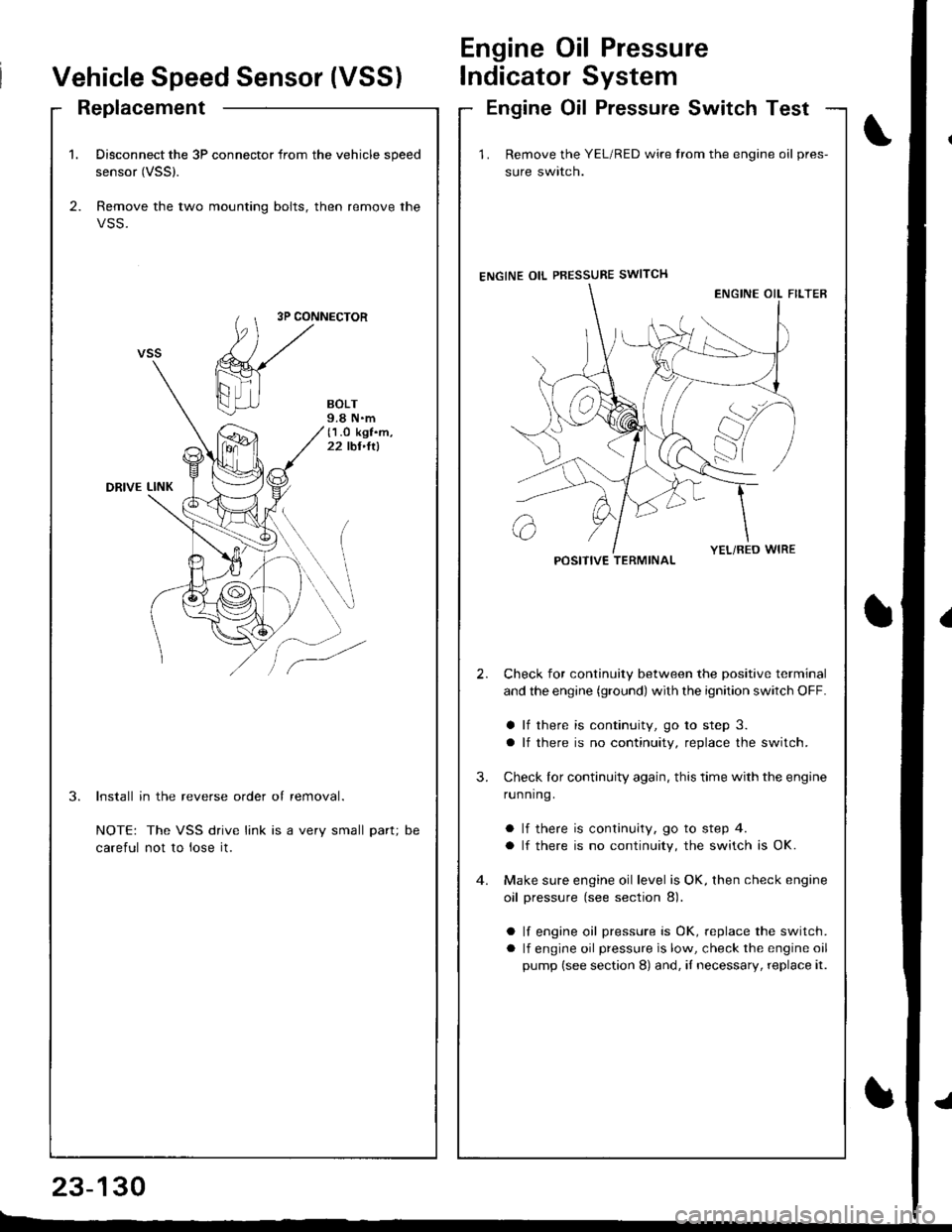
1. Disconnect the 3P connector from the vehicle speed
sensor (VSSl.
2. Remove the two mounting bolts, then remove the
VSS.
3P CONNECTOR
BOLT9.8 N.m(1.O kgf.m,22 tbt,ltl
DRIVE LINK
3.Install in the reverse order of removal.
NOTE: The VSS drive link is a very small part;
careful not to lose it.
DC
Vehicle Speed Sensor (VSS)
Engine Oil Pressure
lndicator System
ReplacementEngine Oil Pressure Switch Test
23-130
E-_
1 . Remove the YEL/RED wire trom the engine oil pres-
sure swlrcn.
ENGINE OIL PBESSURE SWITCH
Check for continuity between the positive terminal
and the engine (ground) with the ignition switch OFF.
a lf there is continuity, go to step 3.
a lf there is no continuity, replace the switch.
Check lor continuity again, this time with the engine
running.
a lf there is continuity, go to step 4.
a lf there is no continuity, the switch is OK.
Make sure engine oil level is OK, then check engine
oil pressure (see section 8).
a lf engine oil pressure is OK, replace the switch.
a lf engine oil pressure is low, check the engine oil
pump (see section 8) and, iI necessary, replace it.
2.
3.
POSITIVE TERMINAL
Page 1188 of 1681

)
{
t.t
t.!
23-131
Fuel Gauge
Gauge Test
NOTE: Refer to page 23-123 for the fuel gauge system
circuit.
1. Check the No. 25 (7.5 A) fuse in the under-dash
fuse/relay box before testing.
2. Remove the rear seat (see section 20).
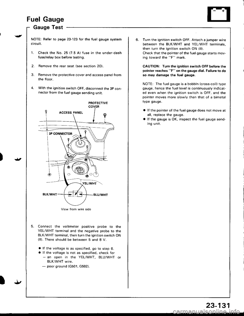
Remove the protective cover and access panel from
the tloor.
With the ignition switch OFF, disconnect the 3p con-nector from the fuel gauge sending unit.
3.
4.
5.
PROTECTIVECOVER
Connect the voltmeter positive probe to the
YEL/WHT terminal and the negative probe to the
BLK/WHT terminal, then turn the ignition switch ON(ll). The.e should be between 5 and 8 V.
a lf the voltage is as specified, go to step 6.a lI the voltage is not as specified, check for- an open in the YEL/WHT, BLU/WHT or
BLK/WHT wire.- poor ground (G501, G502).
3P CONNECTOR
View from wire side
6.Turn the ignition switch OFF. Attach a jumper wire
between the BLKMHT and YEL/WHT terminals,
then turn the ignition switch ON {1.,.
Check that the pointer of the fuel gauge starls mov-
ing toward the "F" mark.
CAUTION: Turn the ignition switch OFF before the
pointer reaches "F" on the gauge dial, Failure to do
so may damage the tuel gauge.
NOTE: The fuel gauge is a bobbin (cross-coil) type
gauge, hence the fuel level is continuously indicat-
ed even when the ignition switch is OFF, and thepointer moves more slowlv than that ol a bimetal
rype gauge.
a lf the pointer ol the fuel gauge does not move at
all, replace the gauge.
a It the gauge is OK, inspect the fuel gauge send-
ing unit.