Page 1110 of 1681

J
)1 -
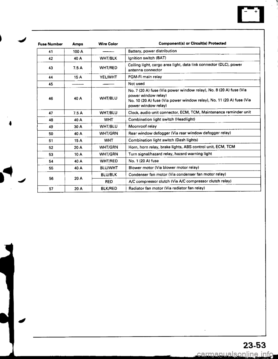
Fuso NumborAmpsWir€ ColorComponent(s) or Circuh(rl Protastcd
41100 ABattery. power distribution
4240AWHT/BLKlgnition switch (BAT)
437.5 AWHT/REDCeiling light, cargo area light, data link connector (DLCl, power
antenna connector
44't5 AYEL/WHTPGM-Fl main relay
45Not used
4640AWHT/8LU
No. 7 (20 A) fuse (Via power window relay), No. 8 (20 A) tuse (Via
power window relay)
No. 10 (20 A) fuse (Via power window relay), No. 11 (20 A) fuse (Via
power window relay)
417.5 AWHT/BLUClock,8udio unit connector, ECM, TCM, Maint€nance reminder unit
4840AWHTCombination light switch (Headlight)
4930AWHT/BLUMoonroof relay
5040AWHT/GRNRear window defogger {Via rear window defogger relay)
51154WHTCombination light switch (Dash lights)
20AWHT/GRNHorn, horn relay, brake lights, AgS control unit, ECM, TCM
10AWHT/GRNTurn signal/hazard relay, hazard warning light
5440AWHT/flEDNo. 1 (20 A) fuse
40ABLU/WHTBlower motor (Via blower motor relsy)
56204BLU/BLKCondenser fan motor (Via condenser {an motor relay)
REDA,/C compressor clutch (via Ay'c comp.essor clutch relay)
57204BLVREDRadiator f8n motor (Via radiator fan relay)
23-53
Page 1111 of 1681
Power
Circuit
Distribution
ldentification
UNDER.HOOO ABSFUSE/RELAY 8OX
ABS OUMP MO'OF CELAY
I Li,z (via ABS lail.sale telay)
L lgS moou aror un r(Va ABS lai.sale retay)
N0.62 (20A)FUSElvia ABS lai-l\sale re ay /
ABS pump motor
ABS conlrol unir (MCK)
ABS con$olunit (PMR)
Hazad warning lightTurn signal/hazard elay(Viaswilch)Horn
BRN/YEL
YEUFED
8LK - Shner molor
BLK/RED
T
G1
GmlG401
ALTERNATORwHriGRN---
WHT/GRN -No rs {7.5A1 V"LL,,r,
_f,-"*
GRNMHT -F ABS conlrollnrt
t- EcM TcM_ &eke ughts
GRN/RED - ECM
*HT,BLK --+ ig|ryJ,itil.* F^r
F UNDEF OASHvlHi.nED -I4 > FUSE FELAY BOXLz {To page 23 59)
YEITWHT - PGM.Flmain retav
T. UNDER.DASHI/HT a_U -l 'l > .uSE RELAV 8OXfro page 23 57)
ClockECM
TCMMainlenance reminder unl
MT/GRN --T Horn relav
-ol- WHTTGRN -l
BRAKE SWITCHION: Pedal depressedl
23-54
Page 1127 of 1681
. Horn relay
a Hatch release relay
. Starter out relay
Power Relays
. ABS pump motor relay
. ABS fail-safe relay
Page 1264 of 1681
Horn
Component Location lndex
JSRS components are located in this area. Review the
SRS component locations, precautions, and procedures
in the SRS section {23) before performing repairs or ser-
vtce,
HORNTest, page 23 211
HORN SWITCHESTest, page 23-209
CABLE REELReplacement, page 23 322UNDER-DASHFUSE/BELAY BOX
{---=-\s":=',-i=
il
-rrj _LJLi lJJJ I -.r ----------;- - t--t -----,------- L I t---HORN RELAY
I Wire colo6: WHT/GRN, WHT/GRN ILBLU/GRN, and BLU/REO ITest, page 23-70
)
23-207
Page 1266 of 1681

SwitchTest
SRS comDonents are located in this area. Review the
SRS component locations, precautions, and procedures
in the SRS section (23) before performing repairs or ser-
vtce.
NOTE: The original radio has a coded thett protection cir-
cuit. Be sure to get the customer's code number beJore- disconnecting the battery.- removing the No. 47 (7.5 A) fuse from the under-hood
fuse/relay box.- removing the radio.
After service, reconnect Dower to the radio and turn it on.
When the word "CODE" is displayed, enter the customer's
5-digit code to restore radio operation
Disconnect the battery negative cable, then discon-
nect the positive cable, and wait at least three min-
uIes.
Disconnect each airbag connector.
Driver's Side:
a Remove the access panel from the steering wheel,
then disconnect the 2P connector between the
driver's airbag and cable reel.
Front Passenger's Side:
. Remove the glove box,
a Disconnect the 2P connector between the front
passenger's airbag and SRS main harness.
1.
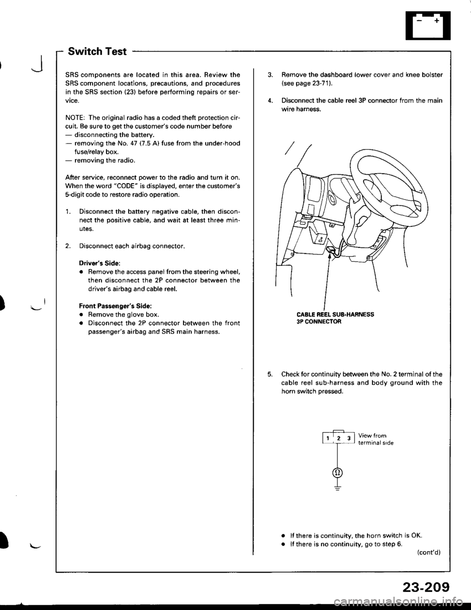
Remove the dashboard lower cover and knee bolster(see page 23-71).
Disconnect the cable reel 3P conneclor from the main
wtre narness.
CABLE REEL SUB.HARNESS3P CONNECTOR
Check for continuitv between the No. 2 terminal of the
cable reel sub-harness and body ground with the
horn switch Dressed.
terminalside
a
It there is continuity, the horn switch is OK.
lf there is no continuity, go to step 6. (cont,d)
r-P r11 2 3l-t-
I
I\-J
)
I
23-209
Page 1267 of 1681
Horn
Switch Test (cont'd)
Remove the driver's airbag assembly (refer to the
SRS sub-section in section 23).
Check for continuity between the No. 2 terminal of
the cable reel sub-harness 3P connector and horn
Dositive terminal.
lf there is no continuity. replace the cable reel.
lf there is continuity, replace the horn switch.
a
a
HORN POSITIVE TERMINAL
23-210
9.
10.
11.
12.
lf all tests prove OK, reinstall the driver's airbag
assembly (re{er to the SRS sub-section in section 23).
Reconnect the driver's airbag connectors, and rein-
stall the access panel on the steering wheel.
Reconnect the front passenger's airbag connector,
and reinstall the glove box.
Connect the battery positive cable, then connect the
negative cable.
Atter installing the airbag assembly, confirm that
- the SRS indicator light should come on for about
six seconds and then go off with the ignition switch
oN 0t).- the horn sounds with the horn button pressed.
Page 1268 of 1681
Horn Test
1.Remove the front bumper (see section 20).
Disconnect the 1P connector from the horn.
lP CONNECTOR
MOUNNNG BOLT
IBODY GROUND}
Test the horn by connecting battery power to one
terminal and grounding the body ground. The horn
should sound.
lf the horn fails to sound, check tor:- taulty horn assembly.- faulty mounting bolt.
J
Page 1311 of 1681

t
t;
i'l
I
dil
Gruise Gontrol
Troubleshooting
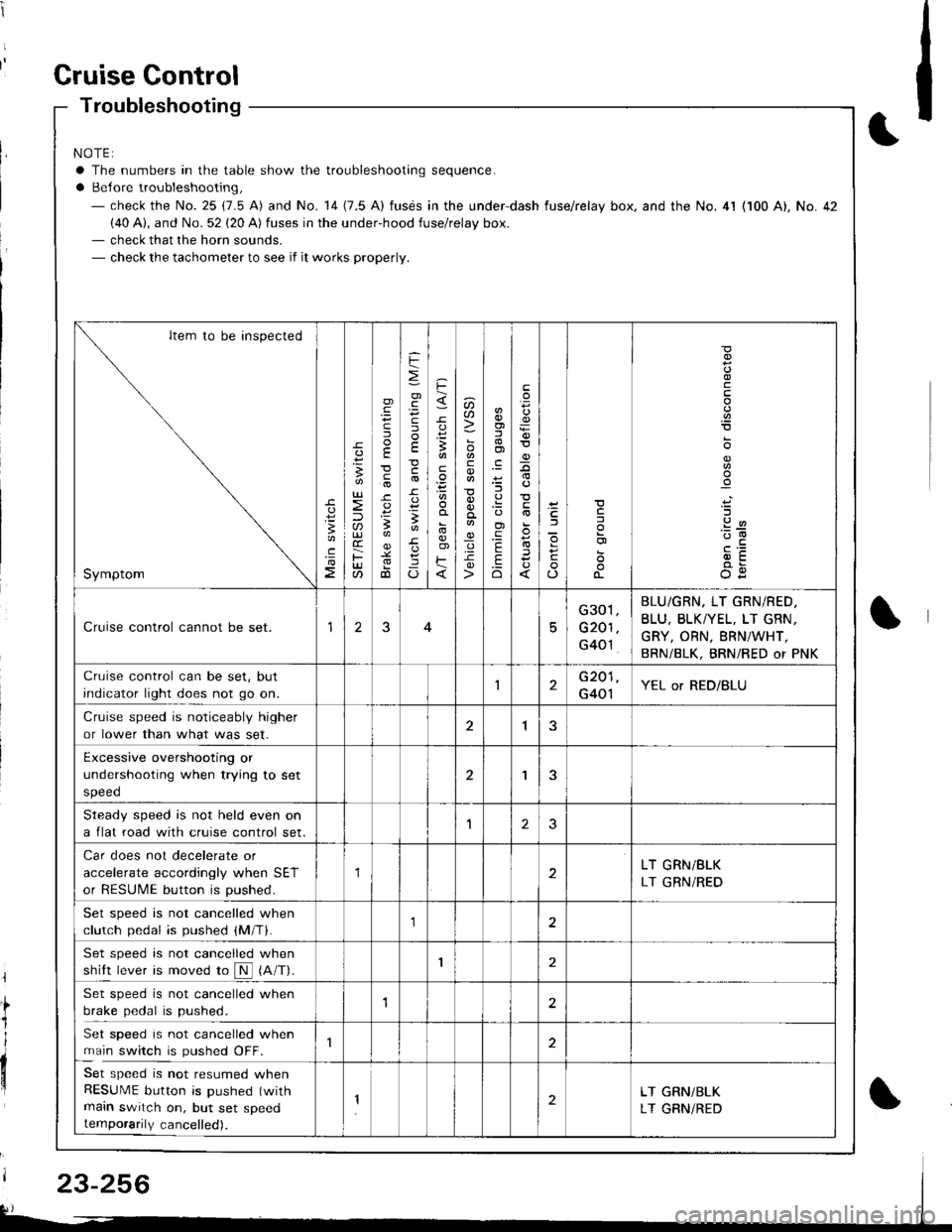
NOTE:
a The numbers in the table show the troubleshooting sequence.
a Belore troubleshooting,- check the No. 25 (7.5 A) and No. 14 (7.5 A) fusds in the under-dash fuse/relay box. and the No. 4l (100 A), No. 42(40 A), and No. 52 (20 A) fuses in the under-hood fuse/relay box.- check that the horn sounds.- check the tachometer to see if it works properly.
Item to be inspected
Symptom
c
:3
UJ
lU)(r
F(t
)
E
c
.
F
=
.g
E
-c
!-
Io
F
3
E
o)F
u)U'
co
_q.9-c
o)f,
ol
;l
E
.Eo
F
E
_9
)a
o
o-
o
c
.2
'::-c
OE
Cruise control cannot be set.15
G301
G201
G40't
BLU/GRN, LT GRN/RED.
BLU, BLKTYEL, LT GRN.
GRY, ORN, BRNiWHT,
BRN/BLK, BRNi RED or PNK
Cruise control can be set, but
indicator light does not go on.1G201
G401YEL or RED/BLU
Cruise speed is noticeably higher
or lower than what was set.1
Excessive overshooting or
undershooting when trying to set
speed
'I
Steadv soeed is not held even on
a flat road with cruise control set.1J
Car does not decelerate or
accelerate accordingly when SET
or RESUME button is pushed.
1LT GRN/BLK
LT GRN/RED
Set speed is not cancelled when
clutch pedal is pushed (M/T).1
Set speed is not cancelled when
shift lever is moved ro N (A/T).I
Set speed is not cancelled when
brake pedal is pushed.12
Set speed is not cancelled when
main switch is pushed OFF.
Set speed is not resumed whenRESUME button is pushed (with
main switch on, but set speedtemporarily cancelled).
2LT GRN/BLK
LT GRNiRED
23-256