1998 HONDA INTEGRA high beam
[x] Cancel search: high beamPage 1217 of 1681
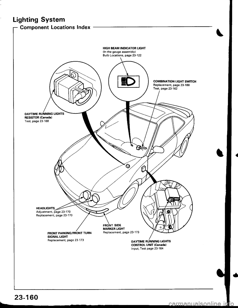
Lighting System
OAYTIMERESISTOR (Can.dal
Test, page 23-168
HEADLIGHTS
Component Locations Index
HIGH BEAM INDICATOR LIGHT{ln the galge assembly}Bulb Locations. page 23-122
COMAINATION LIGHT SwlTCHReplscement, page 23-168Test, page 23-162
Adjustment, page 23-170Replacement, page 23-170
CONTBOL UNIT {Can.d.)Input, Test page 23-164
23-160
Page 1222 of 1681
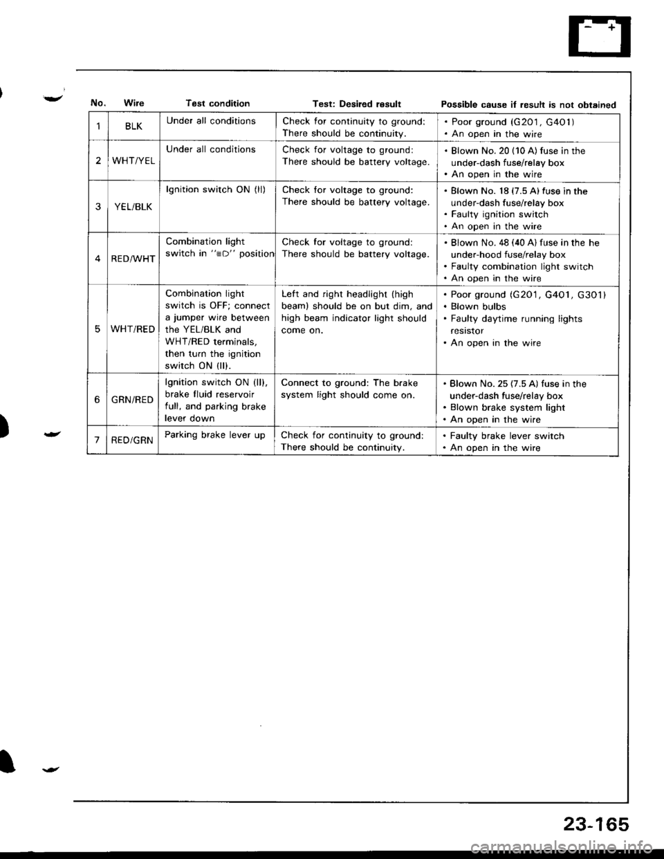
Tsst conditionTest: Desiled resultPossible cause it result is not obtained
)
BLKUnder all conditionsCheck for continuity to ground:
There should be continuity.
. Poor ground (G201 , G40l ). An open in the wire
2WHT/YEL
Under all conditionsCheck for voltage to ground:
There should be battery voltage.
. Blown No. 20 (10 A) fus€ in the
under-dash fuse/relay box. An open in the wire
YEL/BLK
lgnition switch ON (ll)Check for voltage to ground:
There should be battery voltage.
Blown No. 18 (7.5 A)fuse in the
under-dash fuse/relay box
Faulty ignition switch
An open in the wire
RED/WHT
Combination light
switch in "=D" position
Check for voltage to ground:
There should be battery voltage.
Blown No. 48 (40 A) fuse in the he
under-hood fuse/relay box
Faulty combination light switch
An open in the wire
WHT/RED
Combination light
switch is OFF; connect
a jumper wire between
the YEL/BLK and
WHT/RED terminals,
then turn the ignition
switch ON (ll).
Left and right headlight (high
beaml should be on but dim, and
high beam indicator light should
come on.
Poor ground (G20'1, G4O1, G301)
Blown bulbs
Faulty daytime running lights
resrstor
An open in the wire
6GRN/RED
lgnition switch ON (ll).
brake fluid reservoir
full, and parking brake
levef oown
Connect to ground: The b.ake
system light should come on.
Blown No. 25 (7.5 A) fuse in the
under-dash fuse/relay box
Blown brake system light
An open in the wire
'1RED/GRNParking brake lever upCheck for continuity to ground:
There should be continuity.
. Faulty brake lever switch. An open in the wire
23-165
Page 1227 of 1681
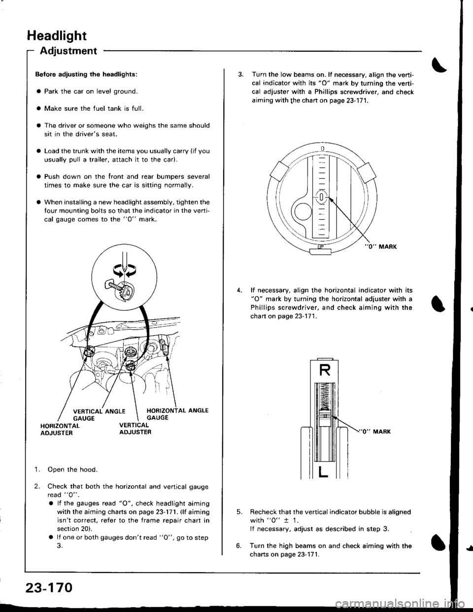
Headlight
Adjustment
Befole adiusting the headlights:
a Park the car on level ground.
a Make sure the fuel tank is full.
The driver or someone who weighs the same should
sit in the driver's seat.
Load the trunk with the items you usually carry (if you
usually pull a trailer, attach jt to the car).
Push down on the front and rear bumpers several
times to make sure the car is sitting normally.
When installing a new headlight assembly, tighten the
four mounting bolts so that the indicator in the verti-
cal gauge comes to the "O" mark.
HORIZONTAL ANGLEGAUGE
HORIZONTALADJUSTER
'1. Open the hood.
2. Check that both the horizontal and vertical gauge
rcad "O" .
a lf the gauges tead "O", check headlight aiming
with the aiming charts on page 23-171. (lf aiming
isn't correct. refer to the frame repair chart in
section 20).
a lf one or both gauges don't read "O", go to step
23-170
3. Turn the low beams on. lf necessary, align the verti-
cal indicator with its "O" mark by turning the verti-
cal adjuster with a Phillips screwdriver, and check
aiming with the chan on page 23-171.
lf necessary, align the horizontal indicator with its"O" mark by turning the horizontal adjuster with a
Phillips screwdriver, and check aiming with the
chart on page 23-171.
5.Recheck that the vertical indicator bubble is aligned
with "0" t 1.
lf necessary, adjust as described in step 3.
Turn the high beams on and check aiming with the
charts on page 23-171.
Page 1228 of 1681
)
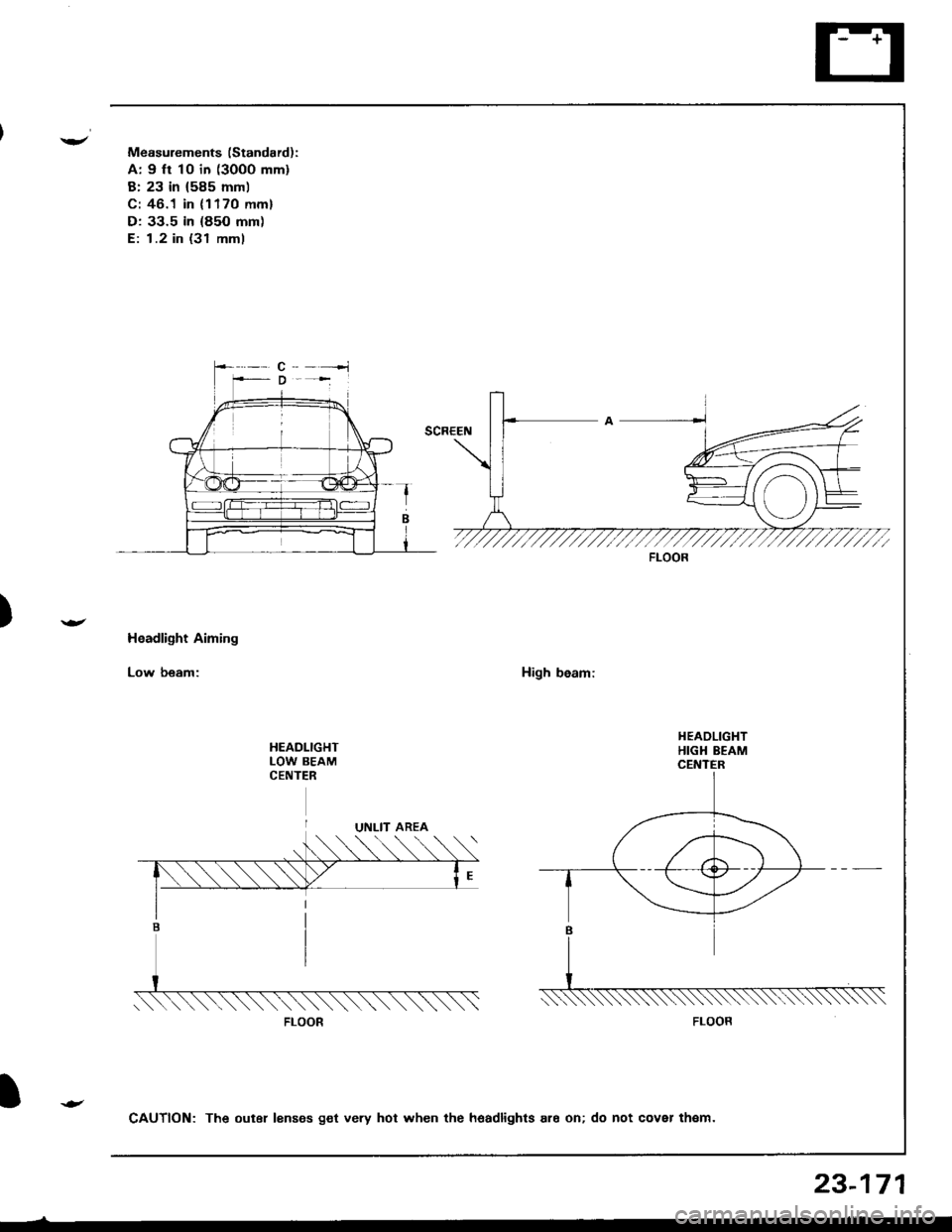
Measurements (Standard):
A: 9 ft 10 in (3000 mm)
B: 23 in (585 mml
C: 46.1 in (1170 mm)
D: 33.5 in (85O mm)
E: 1.2 in (31 mml
Headlight Aiming
Low beam:High beam:
HEADLIGHTLOW BEAMCENTER
FLOOR
FLOOR
CAUTION: The outer lenses get very hot when the hoadlights ar6 on; do not cover th€m.
23-171
Page 1401 of 1681
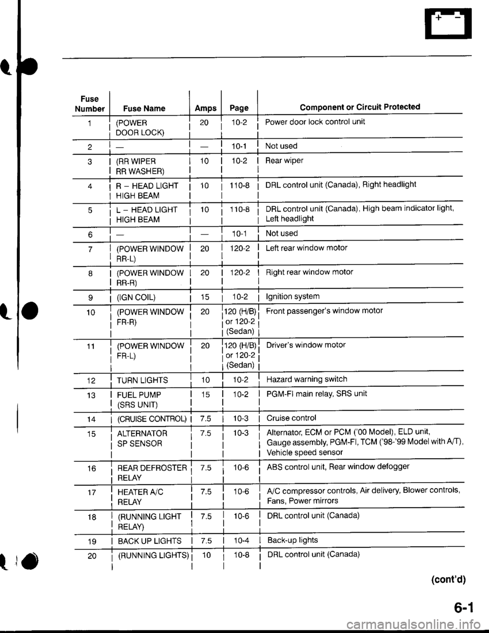
Fuse
NumberFuse NameAmpsPagecomponent or circuit Protected
(POWER
DOOR LOCK)
(RR WIPER
RR WASHER)
R _ HEAD LIGHT
HIGH BEAM
j 1o-2Power door lock control unit
10-2 | Rear wiper
I
tto-e i onLcontrol unit (Canada), Right headlight
L _ HEAD LIGHT
HIGH BEAM
(POWER WINDOW
RR-L)
i 1 10-8i DRL control unit (Canada), High beam indicator light,
i Left headlight
1 0-1Not used
| 1zo-z
I
I Left rear window motor
| (lGN colL)| 15
(POWER WINDOW
FR-R)
(POWEB WINDOW
FR-L)
I Right rear window molor
I
Front passenger's window motol
Driver's window motor
| 120-2
i120 (H/B)
iot 120-2
l(Sedan)
i120 (H/B)
l0:120 ?
IJ13
TURN LIGHTS
FUEL PUMP
(SRS UNIT)
(Sedan)
'lo-2Hazard warning switch
1O-2 | PGM-FI main relay, SRS unit
I
14I (cRUlsE coNTRoL) | 7.510-3 | Cruise control
ALTERNATOR
SP SENSOR
7.510-3Alternator, ECM or PCM ('00 Model), ELD unit,
Gauge assembly, PGM-Fl, TCM ('98-'99 Modelwith A/f),
Vehicle speed sensor
i REAR DEFBOSTER ii RELAY i
10-6i ABS control unit, Rear window defogger
I HEATER A/C
: RELAY
fuC compressor controls, Air delivery, Blower controls,
Fans. Power mirrors
I tnururutruc ucxr I z.s
I otrt av I
I DRL control unit (Canada)10-6
I BACK UP LIGHTS | 7.s | 10-4 I Back-up lights
t
(RUNNTNG LTGHTS) ii DRL control unit (Canada)
(cont'd)
19
6-1
Page 1523 of 1681
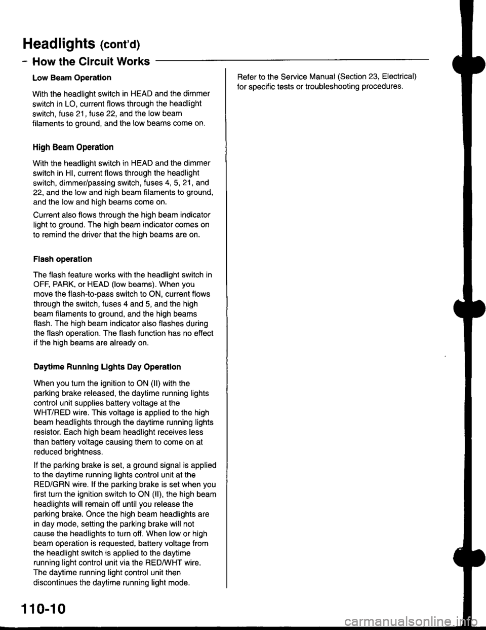
Headlights (cont'd)
- How the Circuit Works
Low Beam OperationRefer to the Service Manual (Section 23, Electrical)
for specific tests or troubleshooting procedures.
With the headlight switch in HEAD and the dimmer
switch in LO, current flows through the headlight
switch, fuse 21 , tuse 22, and the low beam
filaments to ground, and the low beams come on.
tligh Beam Operation
With the headlight switch in HEAD and the dimmer
switch in Hl, current flows through the headlight
switch, dimmer/passing switch, fuses 4, 5, 21, and
22, and the low and high beam filaments to ground,
and the low and high beams come on.
Current also tlows through the high beam indicator
light to ground. The high beam indicator comes on
to remind the driver that the high beams are on.
Flash operation
The flash feature works with the headlight switch in
OFF, PARK, or HEAD (low beams). When you
move the flash-to-pass switch to ON, current flows
through the switch, fuses 4 and 5, and the high
beam filaments to ground, and the high beams
flash. The high beam indicator also flashes during
the flash oDeration. The flash function has no effect
it the high beams are already on.
Daytime Running Lights Day Operation
When you turn the ignition to ON (ll) with the
parking brake released, the daytime running lights
control unit supplies battery voltage at the
WHT/RED wire. This voltage is applied to the high
beam headlights through the daytime running lights
resistor. Each high beam headlight receives less
than battery voltage causing them to come on al
reduced brightness.
lf the parking brake is set, a ground signal is applied
to the daytime running lights control unit at the
RED/GRN wire. It the parking brake is set when you
first turn the ignition switch to ON (ll), the high beam
headlights will remain off until you release the
parking brake. Once the high beam headlights are
in day mode, setting the parking brake will not
cause the headlights to turn off . When low or high
beam operation is requested, baftery voltage trom
the headlight switch is applied to the daytime
running light control unit via the RED/vVHT wire.
The daytime running light control unit then
discontinues the daytime running light mode.
1 10-10
Page 1602 of 1681
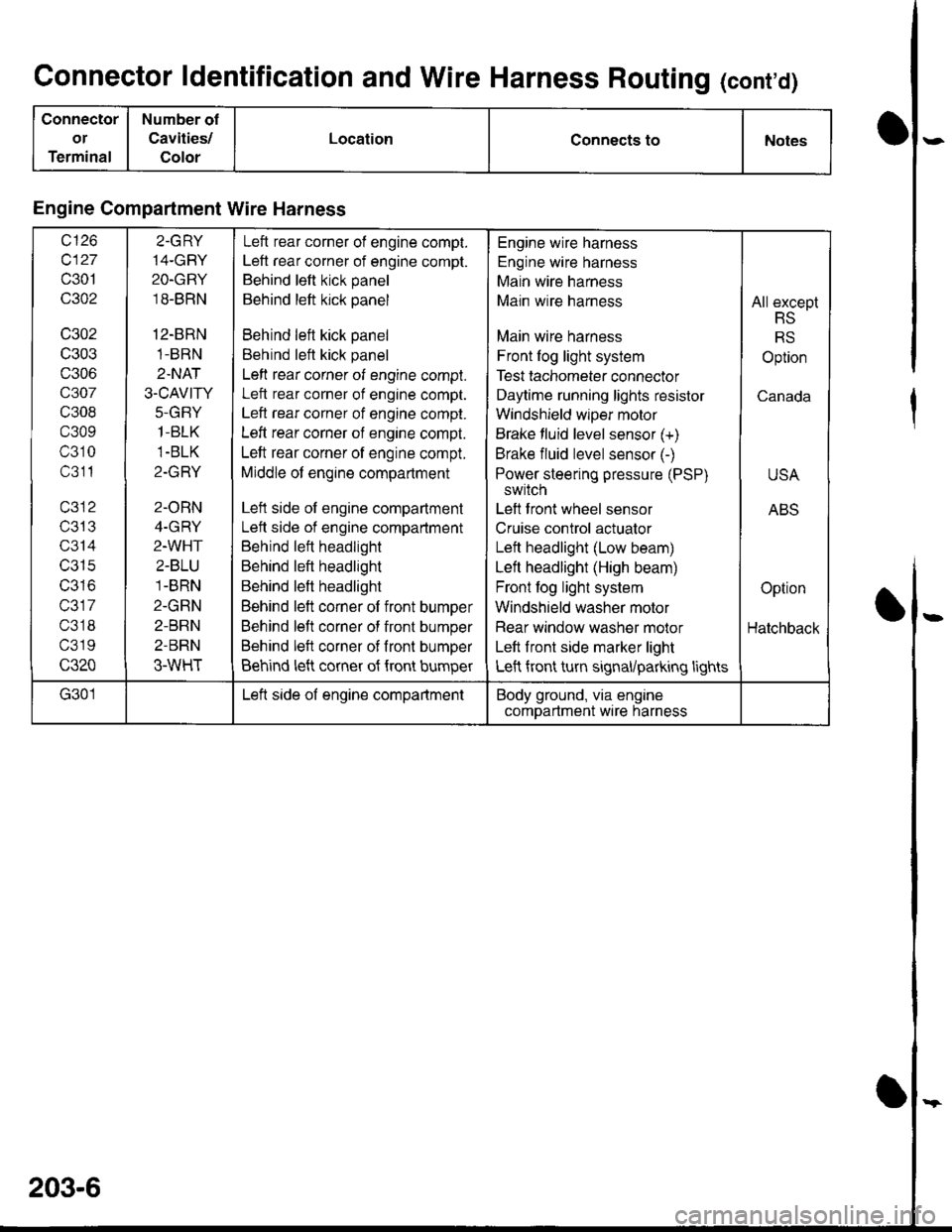
Connector ldentification and Wire Harness Routing (cont'd)
Connector
or
Terminal
Number of
Cavities/
Color
LocationConnects toNotes
Engine Compartment Wire Harness
wt10
c127
c301
c302
c302
c303
c306
c307
c308
c309
c310
c311
T/JIJ
c314
c315
IJJ IO
c317
c318
c319
c320
2.GRY
14-GBY
2O-GRY
18-BRN
12-BRN
1-BRN
2.NAT
3.CAVITY
J-(l|-I Y
1-BLK
1-BLK
Z-IfFI T
2-ORN
4-GRY
2-WHT
2-BLU
1-BRN
2-GRN
2-BRN
2-BRN
3-WHT
Left rear corner of engine compt.
Left rear corner of engine compt.
Behind left kick panel
Behind left kick panel
Behind left kick panel
Behind left kick panel
Left rear corner of engine compt.
Left rear corner of engine compt.
Left rear corner of engine compt.
Left rear corner of engine compt.
Left rear corner of engine compt.
Middle of engine compartment
Left side of engine compartment
Lett side of engine compartment
Behind left headlight
Behind left headlight
Behind left headlight
Behind left corner of front bumper
Behind left corner of front bumper
Behind left corner of fronl bumper
Behind left corner of {ront bumper
Engine wire harness
Engine wire harness
Main wire harness
Main wire harness
Main wire harness
Front log light system
Test tachometer connector
Daytime running lights resistor
Windshield wlper motor
Brake fluid level sensor (+)
Brake fluid level sensor (-)
Power steering pressure (PSP)
switch
Left front wheel sensor
Cruise control actuator
Left headlight (Low beam)
Left headlight (High beam)
Front fog light system
Windshield washer motor
Rear window washer molor
Left front side marker light
Left front turn signal/parking lights
All except
RS
RS
Option
Canada
USA
ABS
Option
Hatchback
G301Left side of engine compartmentBody ground, via engine
comDartment wire harness
203-6
Page 1604 of 1681
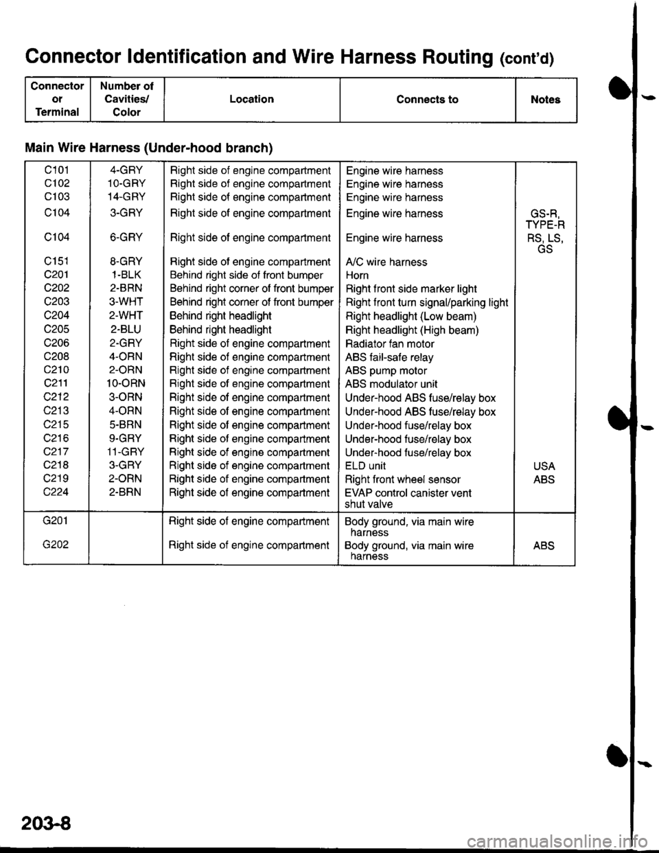
Connector ldentification and Wire Harness Routing (conrd)
Connector
ot
Terminal
Number of
Cavities,/
Color
LocationConnects toNotes
Main Wire Harness (Under-hood branch)
c101
c102
cl03
c104
c104
c151
c201
c202
c203
c204
c205
c206
c208
c210
c211
c212
c213
c215
wz to
c217
c218
c219
4-GBY
1O.GRY
14.GRY
3-GRY
6-GRY
8.GRY
1-BLK
2-BRN
3.WHT
2-WHT
2-BLU
2-GRY
4-ORN
2-ORN
10-oRN
3-ORN
4-ORN
5.BRN
9.GRY
11-GBY
3-GBY
2-ORN
2-BRN
Right side of engine compadment
Right side of engine compartment
Right side of engine compartment
Right side of engine compartment
Right side of engine compartment
Right side of engine compartment
Behind right side of front bumper
Behind right corner of front bumper
Behind right corner of front bumper
Behind right headlight
Behind right headlight
Right side of engine compartment
Righl side of engine compartment
Right side of engine compartment
Bight side of engine compartment
Right side of engine compartment
Right side of engine compartment
Right side of engine compartment
Right side of engine companment
Right side of engine compartment
Right side of engine compartment
Right side of engine compartment
Right side of engine compartment
Engine wire harness
Engine wire harness
Engine wire harness
Engine wire harness
Engine wire harness
A,/C wire harness
Horn
Right f ront side marker light
Right front turn signal/parking light
Right headlight (Low beam)
Right headlight (High beam)
Radiator fan motor
ABS faiFsafe relay
ABS pump molor
ABS modulator unit
Under-hood ABS fuse/relay box
Under-hood ABS tusehelay box
Under-hood fuse/relay box
Under-hood fuse/relay box
Under-hood fuse/relay box
ELU UNII
Right front wheel sensor
EVAP control canister vent
shut valve
GS.R,
TYPE-R
RS, LS,
GS
USA
ABS
Right side of engine compartment
Right side of engine compartment
Body ground, via main wire
harness
Body ground, via main wireharnessABS
2()3€