Page 1058 of 1681
J
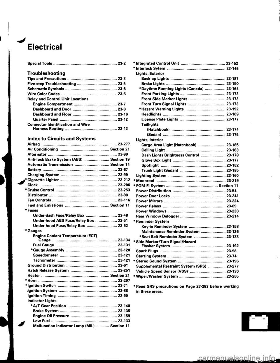
Electrical
Speciaf Toofs ..........................23-2
Troubleshooting
Tips 8nd Precautions .......................,..,.,.,.,.,......,..., 23-3
Five-step Troubleshooting ............,......,.,.,...,..,....., 23-5
Schsmatic Svmbols ...............23-6
Wire Color Code3 .. ................. 23-6
Relay and Control Unit Locations
Engine Compartment ......,.,.................,.,.,.,.,.,,,, 23-7
Dashboard and Door .........,...........,.....,.,....,.,.... 23-8
Dashboard and Floor ......................................... 23-10
Ouarter Pan€f .,,.,...,.,..,...,,,23-12
Connector ldontification and WireHarness Routing ......,.,......23-'13
Index to Circuits and Systems
Airbag
* Integrated Control Unit .....,.,.,.....23-152* Interlock Sytem .,...,.,...........,. 23.146
Lights, Exterior
Eack-up LighB ..................23.187
Brake Ligh$ ......................23-190*Daytime Running Lights (Canada) ................... 23"164
Front Parking Lights .......................................... 23-173
Front Side Marker Lights .................................. 23-173
Front Turn Signal Lights ..................-.......,...,.,. 23-173* Hazard Warning Lights ....................,........,....... 23-192
Headlights.....23-169
23-253 powerDistribution..................... 23-5/r
Air Conditioning.....,....... Soction 21
Alternator ..........,................... 23.99
iCigarette Lighter .........23-212
*Cruise Control
Distributor
'.'.,.'.'.,.'...,,,,.,''.'.,.',.'''.' 23.277
.............................. 23.88
................... 23-90lgnition Timing ......
Indicator Lights
Key-in Reminder System
Maintenance Reminder System*Seat Belt R€mindor System .,...........................* Side Marker/Turn Signal/HazardFlashcr Svstem .................23-192
Spark Plugs ............................23-98
Starting System .....................23-74* Stereo Sound System ...,......,..........,...,......,.,.,.,..,., 23-196
Supplemental Restraint System (SRS) ................ 23-277
Vshicle Speed Sensor (VSS) ................................. 23.130r Wiper/Washer System .........................................., 23-265
*Read SRS precautions on Psge 23-283 before working
in those areas,
23-154
23.136
23"133
Page 1217 of 1681
Lighting System
OAYTIMERESISTOR (Can.dal
Test, page 23-168
HEADLIGHTS
Component Locations Index
HIGH BEAM INDICATOR LIGHT{ln the galge assembly}Bulb Locations. page 23-122
COMAINATION LIGHT SwlTCHReplscement, page 23-168Test, page 23-162
Adjustment, page 23-170Replacement, page 23-170
CONTBOL UNIT {Can.d.)Input, Test page 23-164
23-160
Page 1226 of 1681
)
Headlight
Description
The low beam lights are projector-type lights which are more compact while maintaining sufticient brightness. Bundlingthe light rays reduces stray light and yields a spotlight-effect which improves visibility during night or foul weather driving.For easier aiming, the headlights are equipped with vertical and horizontal gauges.
NOTE: As the outer lenses are made of a resin material, don't cover the headlights when they a.e turned on.
OUTER LENSCONVEX LENSSU8-REFLECTORSECOND FOCUSINTERRUPTER PLATEREFLECTORFIRST FOCUSBULB
23-169
Page 1227 of 1681
Headlight
Adjustment
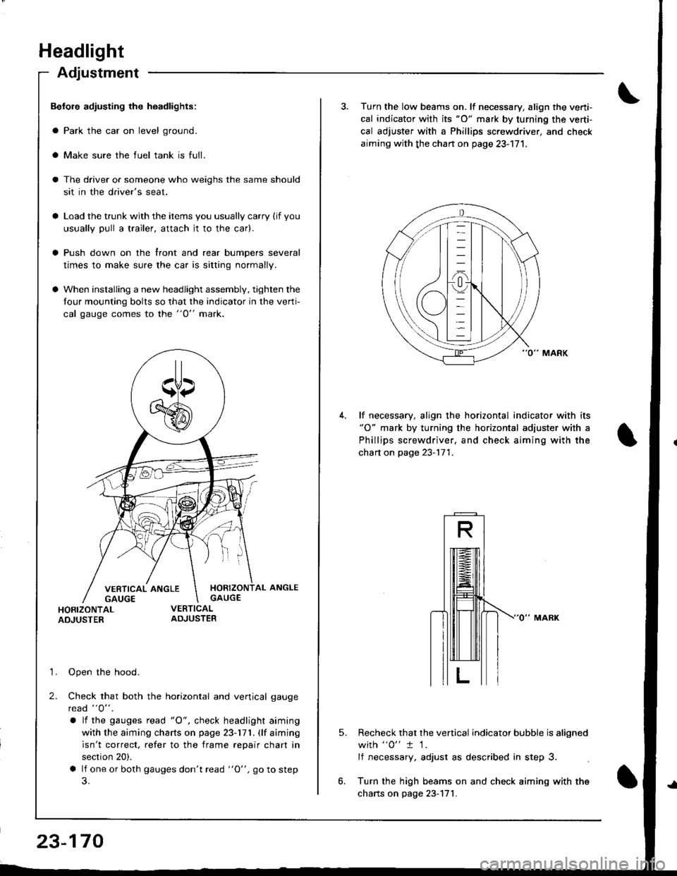
Befole adiusting the headlights:
a Park the car on level ground.
a Make sure the fuel tank is full.
The driver or someone who weighs the same should
sit in the driver's seat.
Load the trunk with the items you usually carry (if you
usually pull a trailer, attach jt to the car).
Push down on the front and rear bumpers several
times to make sure the car is sitting normally.
When installing a new headlight assembly, tighten the
four mounting bolts so that the indicator in the verti-
cal gauge comes to the "O" mark.
HORIZONTAL ANGLEGAUGE
HORIZONTALADJUSTER
'1. Open the hood.
2. Check that both the horizontal and vertical gauge
rcad "O" .
a lf the gauges tead "O", check headlight aiming
with the aiming charts on page 23-171. (lf aiming
isn't correct. refer to the frame repair chart in
section 20).
a lf one or both gauges don't read "O", go to step
23-170
3. Turn the low beams on. lf necessary, align the verti-
cal indicator with its "O" mark by turning the verti-
cal adjuster with a Phillips screwdriver, and check
aiming with the chan on page 23-171.
lf necessary, align the horizontal indicator with its"O" mark by turning the horizontal adjuster with a
Phillips screwdriver, and check aiming with the
chart on page 23-171.
5.Recheck that the vertical indicator bubble is aligned
with "0" t 1.
lf necessary, adjust as described in step 3.
Turn the high beams on and check aiming with the
charts on page 23-171.
Page 1229 of 1681
Headlight
Headlight Replacement
1. Remove the front bumper (see section 20).
2. Remove the mounting bolts, then pull out the head-
light, and disconnect the connectors from it.
After replacement, the horizontal and venical aim-
ing must be checked using conventional methods.
Use the aiming charts on page 23-171.
Bulb Replacement
CAUTION:
a Halogen headlights can becomo very hot in use; do
not touch them or the attaching haldware imm6diately
after they have been tuh6d ott.a Do not try to replace or cl6an the headlights with tho
lights on.
1. Disconnect the 2P connector(s) from the headlight.
Turn the bulb(s) counterclockwise and remove the
bulb(s).
2P CONNECTORS
HEADLIGHT
2PCONNECTOR
2P CONNECTOR
23-172
Page 1383 of 1681
).1
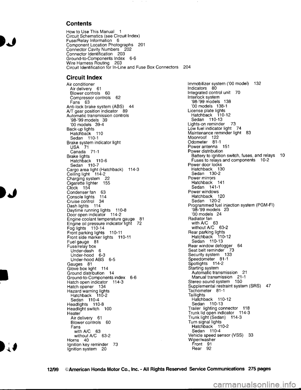
Contents
How to Use This l\.4anual 1Circuit Schematics (see Circuit Index)Fuse/Relaylnformation 6ComponentLocation Photographs 201
Connector Cavity Numbers 202Connectorldentification 203
Ground-to-Components Index 6-6Wire Harness Routing 203Circuit ldentification lor ln-Line and Fuse Box Connectors
Circuit Index
Air conditionerAir delivery 61Blower controls 60Compressor controls 62Fans 63Anti-lock brake system (ABS) 44A/T gear position indicator 89Automatic transmission controls'98199 models 39'00 models 39-4Back-up lightsHatchback 110Sedan 110- 1Brake system indicator light
USA 71Canada 71-1Brake lightsHatchback 110-6Sedan 110-7Cargo area light (Hatchback) 114-3Ceiling light 114-2Charging system 22Cigarette lighter 155
Clock 154Condenser fan 63Console lights 114Cruise control 34Dash lights 1 14Daytime running lights 110-8Door open indicator 114-2Engine coolant temperature gauge 81Engine oil pressure indicator light 72Fog lights 110-14Front parking lights 110-11Front side marker lights 110-11Fuel gauge 81Fuse/relay boxUnder-dash 6Under-hood 6-3Under-hood ABS 6-5Gauges 81Glove box light 114Ground distribution 14Ground-to-Componentsindex 6-6Hatch open indicator '114-3
Hatch opener '134
Hazard warning lightsHatchback 'l l0-2Sedan 110-4Headlights 1'10-8Headlight switch 100HeaterAir delivery 61Blower controls 60Fanswith A,/C 63without A,/C 63-2Horns 40lgnilion key reminder 73lgnition system 20
204
lmmobilizer system ('00 model) 132lndicators 80Integrated control unit 70Interlock system'98199 models 138'00 models 138-1License plate lightsHatchback 110-12Sedan 110-13Lights-on reminder 73Low fuel indicator light 74l\,4aintenance reminder light 83l\iloonroof 122Odometer 81-1Power antenna 151Power distributionBattery to ignilion switch, fuses, and relays
Fuses to relays and components 10-2Power door locksHatchback '130
Sedan 130-2Power mirrorsHatchback 141Sedan 141-1Power windowsHatchback 120Sedan 120-2Programmed fuel injection system (PGM-Fl)'98199 models 23'00 models 24Radiator fanwith tuC 63without A,/C 63-2Rear parking lightsHatchback 110-12Sedan 110- 13Rear window defogger 64Seat belt reminder 73Security system 133Speedometer Il-1Spotlights 114-2Starting syslemAutomalictransmission 21l\.4anualtransmission 21-1Stereo sound system 150Supplemental restraint system (SRS) 47Tachometer 81- 1TaillightsHatchback 110-12Sedan 110-13Trailer lighting conneclor 118Trunk lid open indicator 114-3Trunk light (Sedan) 114-3Turn signal lightsHatchback 110-2Sedan 110-4Vehicle speed sensor (VSS) 33Wiper/washerFront 91Rear 92
10
).1
I
Xr
12Fg oAmerican Honda Motor Co., Inc. - All Rights Reserved Service Communications 275 pages
Page 1390 of 1681
Circuit ldentification for In'Line and Fuse Box Connectors
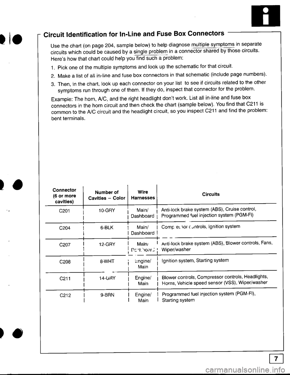
tuse the chart (on page 204, sample below) to help diagnose multiple symptoms in separate
circuits which could be caused by a single problem in a connect,oishared by those circuits'
Here's how that chart could help you find such a problem:
1. Pick one of the multiple symptoms and look up the schematic for that circuit'
2. Make a list of all in-lrne and fuse box connectors in that schematic (include page numbers).
3. Then, in the chart, look up each connector on your list to see if circuits related to the other
symptoms run through one of them. lf they do, inspect that connector for the problem.
Example: The horn, A,/C, and the right headlight don't work. List all in-line and fuse box
connectors in the horn circuit and then check the chart (sample below). You find that C211 is
common to the A,/C circuit and the headlight circuit, so you inspect c211 and find the problem:
bent terminals.
)Connector
(6 or more
cavities)
Numbel of
Cavities - Color
1O-GRY
I 12-GRY
I
Wire
Harnesses
I Main/ | ComP er 'ror c.ntrols,
I Dashboard I
Circuits
Ant!lock brake system (ABS), Cruise control,
Programmed {uel injection system (PGM-FD
!ngrnei
lvlain
lgnition system
Antilock brake system (ABS), BIower controls, Fans,
Wiper/washer
lgnition system, Starting system
Blower controls, Compressor controls, Headlights'
Horns, Vehicle speed sensor (VSS), Wiper/washer
Programmed fuel injection system (PGM-Fl)'
Starting system
Engine/ |Main I
)
Page 1404 of 1681
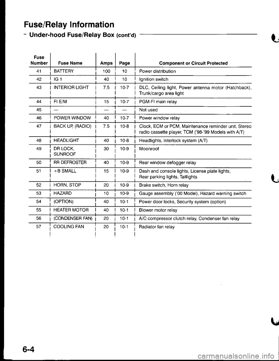
Fuse/Relay I nformation
- Under-hood Fuse/Relay Box (cont'd)
Fuse
NumberFuse NameAmpsPage
BATTERY
I INTERIOR LIGHT
I
1 7.5 110-7 I
I
Component or Circuil Protected
Power distribution
lgnition switch
DLC, Ceiling light, Power antenna motor (Hatchback),
Trunk/cargo area light
47
I Fl E/lvl
POWER WINDOW
I BACK UP (RADTO)
I
15 | 1 0-7 I PGM-FI main relay
Not used
Power window relay
Clock, ECM or PCM, Maintenance reminder unit, Stereo
radio cassette player, TCM ('98-'99 Models with A'/T)
7.5 |10-8
I HEADLIGHT| 40 | 10-8 | Headlights, Interlock system (A/T)
49i DR LOCK,
i suNRooF
10-9 i Moonroof
I
I RR DEFROSTER
+ B SMALL
I Rear window detogger relay
I Dash and console lights, License plate lights,
I Rear parking lights, Taillights
I HORN, STOP
i HAZARD
10-9 | Brake switch, Horn relay
i Gauge assembly ('00 Model), Hazard warning switch
40 | to t I Power door locks, Security system (option)
I HEATER MOTOR II t 0-1I Blower motor relay
20 I 10-1 ; A,/C compressor clutch relay, Condenser fan relay
i Radiator fan relay1 0-1
6-4