1998 HONDA INTEGRA ECO mode
[x] Cancel search: ECO modePage 744 of 1681

Rear Suspension
Suspension Arms (cont'dl
Installation
CAUTION: Any bolB or nuts connected to rubber mounts or bushings should be tightened with the vehicl. on th6
ground.
All except Type R Models:
NOTEi
. Make sure the self-locking bolts on the compensator arms are installed in the same direction.
. "LV" is stamped on the left lower arm and "RV" on the right lower arm.
. "i UP LSR" is stamped on the lett upper arm and "f UP RSR" on the right upper arm.
. The rightand left compensator arm are symmetrical. Install sothe "l UP" mark stamped side faces forward.
. After installing the suspension arm, check the rear wheel alignmentand adjust if necessary (see page 18-4).
I mm BOLT22 N.m {2.2 kgtm, 16lbtft}STABILIZER BARAlign the stabilizer markwith end of stabilizer bushing.
FLANGE BOLT10 x 1.25 mm54 N.m {5.5 kgf.m.40lbtft}
FLANGE BOLTl0 x 1.25 mm39 N m {{.0 kgt.m,29 lbtftl
UPPER ARM
TRAILING ARM
FLANGE EOLT'10 x 1.25 mm54 N.m {5.5 kgf.m, 40lbf.ft}
COMPENSATOR ARM
.-/ SILICONE.5tr@l GREASECOMPENSATOR ARM BUSHING
FLANGE BOI-T10 x 1.25 mm54 N.m (5.5 kgf.m, {O lbf.ft)
FLANGE BOLT10 x 1.25 mm64 N.m 16.5 kgl.m.47 lbf.ft)--- SILICONE.S!@l GREASE
LOWER ARM
LOWER ARM BUSI{ING
-- SILIGONE.S@l GREASE
FLANGE BOLT12 x 1.25 mm64 N.m {6.5 kgf m, 47 lbt.ftl -P'a
,amce gotr/
10 x 1.25 mm
BOLT8 x 1.25 mm22 N.m (2.2 kgt'm, 16 lbf'ftl
39 N.m (4.0 kgf m.29lbtft)stLtcoNEGREASE
UPPER ARM BUSHING
.-.- SILICONES@l GREASE
ADJUSTING BOLT
{FLANGE BOLT)10 x 1.25 mm64 N.m (6.5 kgf.m, 47 lbtft)
k
.g
iP
6[r,
i',
STABILIZER BUSHING
FLANGE BOLT10 x 1.25 mm54 N.m 15.5 kgt.m, 40 lbf.ftl
18-34--Rq
Page 745 of 1681

)Installation
Typ€ R Model:
NOTE;
. Any bolts or nuts connected to rubber mounts or bushings should be tightened with the vehicle on the ground.. "L" is stamped on the left lower arm and "R" is stamped on the right lower arm.. "l UP LS" is stamped on the left upper arm and "l UP RS" is stampedon the right upper arm.. The right and left compensator arms are symmetrical. Install then with the "1 Up" mark facesing forward. After installing the suspension arm, checkthe rearwheel alignmentand adjustitif necessary(see page 18-4).
8 mm BOLT22 N.m (2.2 kgl m, 16 lbt.ftl
STABILIZER BARAlign the stabilizer markwith end of stabilizer bushing.
-ArUPPEB ARM
rz tot+,t \
\.d'. Ja),n[
_oY
t\
a
stLtcoNEGREASEBUSHINGADJUSTING BOLTIFLANGE BOLT}l0 x 1.25 mm6,4 N.m {6.5 kgt m,
FLANGE BOLT'10 x 1.25 mm5,[ N.m 15.5 kg[.m. 40 lbt.ftl
STABILIZER BUSHING
FLANGE BOLT10 x 1.25 mm
FLANGE BOLT10 x 1.25 mrn39 N.m (,r.0 kgf.m.29 lbtftl5/a N.m 15.5 kgl.m, a0
COMPENSATOR AFM
UPPER ARM
TRAILING ARM
FLANGE BOLT10 x 1.25 mm54 N.m 15.5 kgf.m, .{) lbf.ftl..- SILICONE.4@i cREAsECOMPENSATORARM BUSHING
FLANGE BOLI10 r 1.25 mm6,4 N.m (6.5 kgl.m, 47 lbf.Itl
FLANGE BOLT12 x 1.25 mm6a N.m 16.5 kgl.m, a7 lbf.ftl
, ror"orr /
l0 x 1.25 mm39 N.m 14.0 kgf.m, 29 lbt.ftl
FLANGE BOLT8 x 1.25 mm30 N.m 13.1 kgt m, 22 lbf.ftl
..- SILICONE.@ll GREASE
FLANGE BOLT10 x 1.25 mm54 N.m {5.5 kgt m, 40 lbtftl
LOWER ARM
LOWER ARM EUSHING
a
--- SILICONE@l GREASE
-- slLlcoNE&l GREASE
18-35
Page 763 of 1681

Front Brake Caliper
Disassembly/Reassembly
. Never use an air hoss or dry brush to claan b.ake assemblies.. Use an OsHA-approvod vacuum cleane. to avoid breathing braks dust,. Contaminated brake discs or pads roduce stopping ability.. When rausing tha pads. always rein3tall the brake p8d3 in thoir original positions to prevont loss of braking etticlency.
GAUTION: Do not spill brake fluid on the vehicle; it may damags the paint; it brake fluid do6s contast the paint, wash hoff imm€diately with wator.
NOTE:
. Coat the piston, piston seal, and caliper bore with clean brake fluid.. Replace all rubber pans with new ones whenever disassembled,. Clean all pans in brake fluid and air dry; blow out all passages with compressed air,. Before reassembling, check that all parts are free of dust and other foreign particles.
. Replace parts with new ones whenever specified to do so.. Make sure no din or other foreign matter is 8llowed to contaminate the br8ke fluid.. Always use Genuine Honda DOT3 Brake Fluid. Using non-Honda brake fluid can caus6 corrosion and d€crease the liftof the system.
ffl; Use recommended rubber grease in the caliper seal set.
.61, Use recommended seal grease ,n the caliper seal set.
All except Type R Model:
INNER PAD SHIM A
BRAKE PADS
OUTER PAD SHIMCheck for wear.CALIPER BOLT Apply Molykote M7732 N.m {3.3 kgf.m, 2,1 lbtftl to pad side of shim.
WEAR INDICATORInstall inner pad withits wear ;ndicator upward.
nh/t I
T)2
,V--6&,
PAD RETAINERS
'12 x 1.25 mm108 N.m (r1.0 kgl.m.80 tbtftl
CALIPER BMCKET
{cont'd)
PIN BOOT
PIN 8
INNER PAD SHIM B
BANJO BOLT3a N.m {3.5 kgf.m, 25 lbf.ftl
Check for wear.Apply Molykote M77to pad side of shim.
,\
kw
/":^
19-1 1
Page 771 of 1681

Rear Brake Caliper
Disassembly/Reassembly
o Never use an air hose or dry brush to clean brake assemblies.o Use an OSHA-approv€d vacuum cleaner to avoid breathing brake dust.. Conlaminated brake discs or pads reduce stopping ability.. When reusing the pads, always reinstall the brake pads in their original positions to prevent loss of braking efficiency,
CAUTION: Do not spill brake fluid on the vehicle; it may damags the paint; it brake fluid does contast the paint, wash itoff immediately with water,
NOTE:
. Coat the piston. piston seal, and caliper bore with clean brake fluid.. Beplace all rubber parts with new ones whenever disassembled.o Clean all parts in brake fluid and air dry; blow out all passages with compressed air.a Before reassembling, check that all parts are free of dust and other foreign particles.
. Replace parts with new ones whenever specified to do so.. Make sure no dirt or other foreign matter is allowed to contaminate the brake fluid.. Always use Genuine Honda DOT3 Brake Fluid. Using a non-Honda brake fluid can cause corrosion and decrease the lifeof the svstem.
Type R Model:10 mm FLANGE BOLT34 N.m 13.5 kg{.m,25 tbtftlAll 6xc€pt Typ6 R Modet:8 mm FLANGE BOLT23 N.m {2.3 kgf.m, 17 tbf.ft)
BANJO BOLT3,0 N.m (3.5 kgt m, 2s tbtftl
Replace.
;,'"]@: Use recommended rubber grease in the caliper seal set.
.61, Use recommended seal grease in the catiper seal set.
PARKING NUTRETURN SPRING
27 N.m 12.8 kgt m, \2rtbt.frl \
ar"t"o *or"a"=-\9_r.r,e=
LEVER -------rCF
c^M Boor ---f
Re'lace
-==': /t8
"':sst /-
CALIPER BOLTS23 N.m12.3 kgf.m, 17 lbf.ft)
TNNERPADSHTM cAM
lAll except Typs R CALIPER EODYModel)
OUTER PAO SHIM
-db
PAD SPRTNG
a71 ^ V
BRAKEPA''
vUffifi*
,*,
^rrorr /Y'
,/ ^,
O.RINGBeplace.
PINS
BLEED SCREW9 N.m (0.9 kg{.m, 6.5 tbf.ft)
SEALING WASHERSReplace.
PIN BOOT
Page 789 of 1681

I
\
I
Diagnostic Trouble Code (DTC)
DTG lndication
a
t
NOTE: This operation can also be done with the Honda PGM Tester.
1. Connect the SCS short connector to the service check connector (2P) under the glove box,
2. Turn the ignition switch ON (ll) without the brake pedal depressed.
NOTE: lf the brake pedal is depressed when turning the ignition switch ON (ll), the system shifts to the DTC Erasure
mode.
3. The blinking frequency indicates the DTC.
NOTE: lf the DTC is not memorized, the ABS indicator will go off fo r 3.6 seconds, and then come back on.
4. Turn the ignition switch OFF, and remove the SCS short connector.
NOTE: The Malfunction Indicator Lamp (MlL) will stay on after the engine is started if the SCS shon connector is con-
nected.
Conditions lor DTC indication
. Vehicle speed is 6 mph (10 km/h) or less.
. The SCS short connector is connected before the ignition switch is turned ON {ll).
. The brake pedal is released.
ABS INOICATOB
SCS SHORT CONNECTORo?PAZ - 0010100
SERVICE CHECKCONNECTOR I2PI
DTC : 3 3
b
Page 790 of 1681

Diagnostic Trouble Code (DTC)
DTG Erasure (MES Mode)
NOTE: This operation can also be done with the Honda PGM Tester.
1. Connect the SCS short connector to the service check connector (2P) underthe glove box.
2, Deoress the brake pedal.
3. Turn the ignition switch ON (ll) while keeping the brake pedal depressed.
4. Afterthe ABS indicator goes off, release the brake pedal.
5. After the indicator comes on, depress the brake pedal again
6. After the indicator goes off, release the brake pedal again.
7. After a few seconds, the ABS indicator blinks twice and the DTC is erased. lf the indicator does not blink twice, repeat
steps 1 through 6. lf the indicator stays ON after the indicator blinks twice. check the DTC because a problem was
detected during initial diagnosis before shifting to DTC Erasure mode.
8. Turn the ignition switch OFF, and remove the SCS short connector.
Conditions lor DTC erasure
. Vehicle speed is 6 mph (10 km/h) or less.
. The SCS short connector is connected before the ignition switch is turned ON (ll).
. The brake pedal is depressed before the ignition switch isturned ON (ll)
ON
ABS INDICATOF
OFF
DEPRESSED
BRAKE PEDAL
RELEASED
Snilion switch
illr'I'
0.3soc.
'-------t
II2 sec,4 sgc.4 sec.5 aac.
0.3s6c.with in 3 s6c.with in 3 ssc.with in 3 s€c.
T
19-38
Page 1042 of 1681

A/C System Service
Performance Test
The performance test will help determine if the air con,
ditioner system is operating within specifications.
Use only service equipment that is U.L.-listed and is cer,
tified to meet the requirements of SAE J2210 to remove
HFC-134a (R-134a) from the air conditioner svstem.
CAUTION: Exposure to air conditioner retrigerant and
lubricant vapor or mist can irritate eyes, nose and
throat. Avoid breathing the air conditioner refrigerant
and lubricant vapor or mist.
lf accidental system discharge occurs, ventilate work
area before resuming service.
R-134a service equipment or vehicle air conditioner sys-
tems should not be pressure tested or leak tested with
compressed arr.
@ some mixtures of air and R-134a have
been shown to be combustible at elevated Dressures
and can result in fire or explosion causing iniury orproperty damage. Never use compressed air to pressure
test R-134a service equipment or vehicle air conditioner
systems.
Additional health and safety information may be
obtained from the refrigerant and lubricant manufactur-
ers.
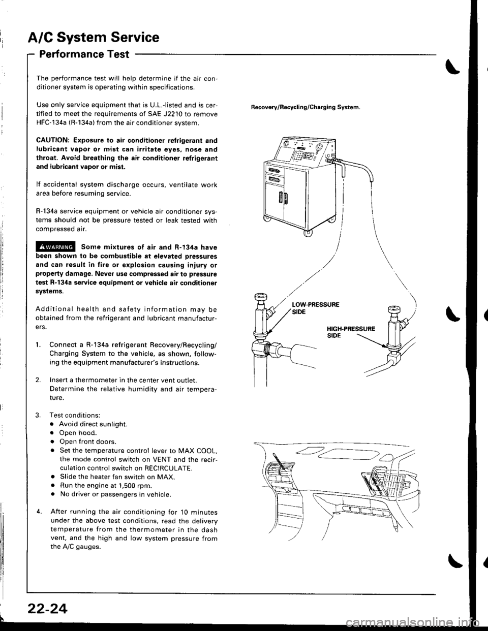
Connect a R-134a refrigerant Recovery/Recycling/
Charging System to the vehicle, as shown, follow-
ing the equipment manufacturer's instructions.
Insen a thermometer in the center vent outlet.
Determine the relative humidity and air tempera-
IUre.
Test conditions:
. Avoid direct sunlight.
. Open hood.
. Open lront doors.
. Set the temperature control lever to MAX COOL,
the mode control switch on VENT and the recir-
culation control switch on RECIRCULATE.. Slide the heater fan switch on MAX.. Run the engine at 1.500 rpm.. No driver or passengers in vehicle.
After running the air conditioning for'10 minutes
under the above test conditions, read the delivery
temperature from the thermometer in the dashvent, and the high and low system pressure from
the A,/C gauges.
Recovo.v/Recycling/Charging System.
LOW.PRESSURE
l
22-24
Page 1296 of 1681

Power Door Locks
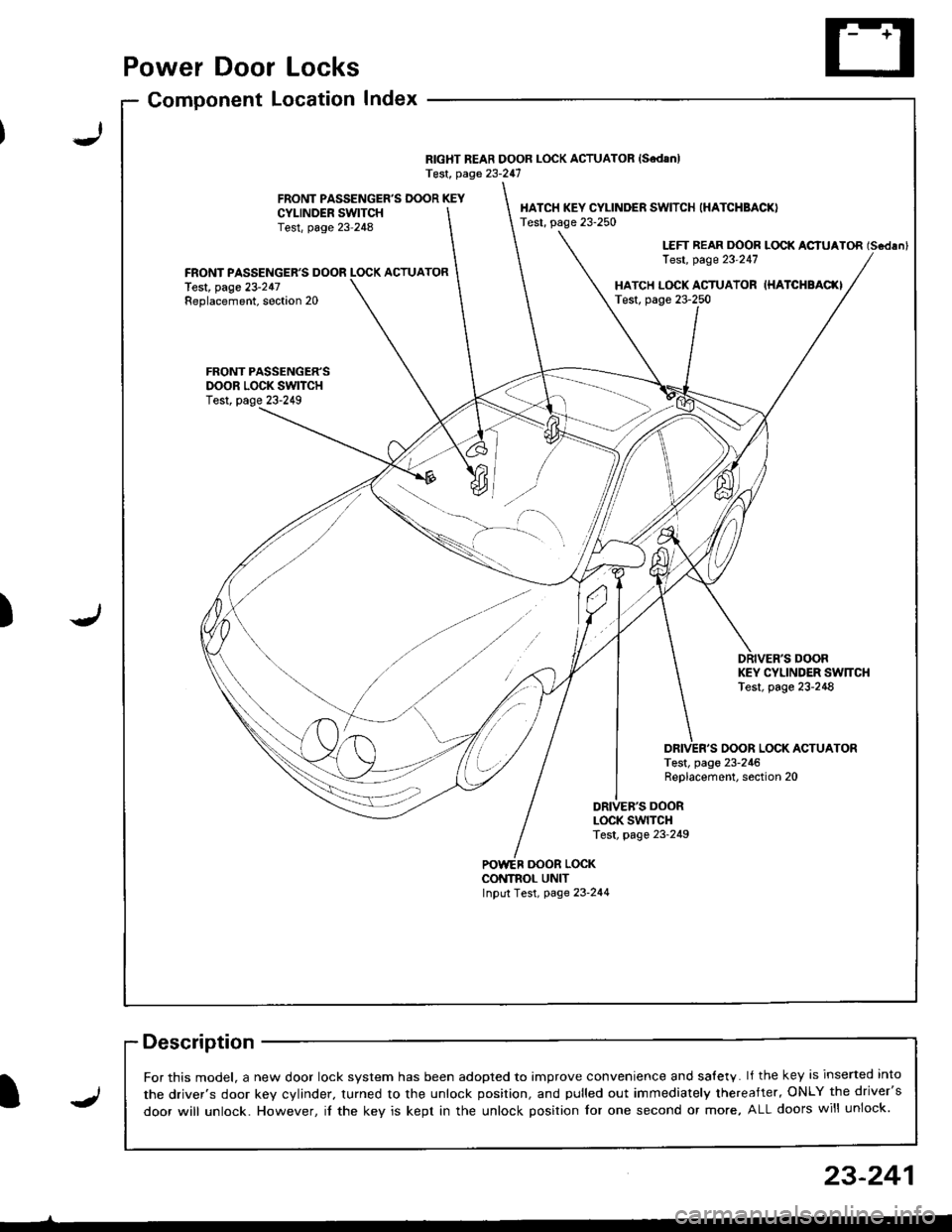
Component LocationIndex
RIGHT REAR DOOR LOCK ACTUATOR {SedanlTest, page 23-247
FRONT PASSENGER'S DOOR KEYCYI-INDER SWITCHTest, page 23-248
HATCH KEY CYLINDER SWITCH (HATCHBACK)
Test, page 23-250
LEFT REAR DOOR LOCK ACIUATOR (Scdlnl
Test, page 23'247FRONT PASSENGER'S DOOR LOCK ACTUATORlest, page 23-247Replacement, soction 20HATCH L(rcK ACTUATOR IHATCHBAC(ITest, page 23-250
FRONT PASSENGER'SDOOR LOCK SWITCHTest, page 23-249
DRIVER'S DOORKEY CYLINDER SW]TCHTest, page 23-248
OOOR LOCK ACTUATORTest, page 23-246Replacement, section 20
DRIVEB'S DOORLOCK SWITCHTest, page 23-249
oooR LocKCONTNOL UNITInput Test, page 23-244
-)
J)
I
For this model, a new door lock svstem has been adooted to imDrove convenience and salety. lf the key is inserted into
the driver's door kev cvlinder. turned to the unlock position, and pulled out immediately thereafter, ONLY the driver's
door will unlock. However, il the key is kept in the unlock position for one second or more, ALL doors will unlock.J
23-241