Page 1294 of 1681
Hatchback:
1. Remove the driver's door panel (see section 20).
2. Disconnecl the 10P connector from the switch.
3. Remove the three mounting screws and the switch.
Sedan:
1. Remove the driver's door panel (see section 20).
2. Disconnect the 16P and 1P connectors from the
swrtcn.
3. Remove the two mounting screws and the switch.
POWER MIRRORswtrcH
scBEws
Master Switch ReplacementPassenger's Window Switch
I-
.J)
I
Replacement
Front:
1 . Remove the passenger's door panel lsee section 20).
2. Disconnect the 5P connector from the switch.
3. Remove the two mounting screws and the switch.
Rear (Sedan);
1. Remove the inner handle (see section 2O).
2. Disconnect the 5P connector from the switch.
3. Remove the two mounting screws and the switch.
wtNDowswrTcH
swtTcH
5P CONNECTOR
IN ER HATOLE
23-239
Page 1307 of 1681
Hatch Opener
Hatch Opener Switch Test/
Replacement
Remove the hatch trim panel (see section 20).
Disconnect the 2P connector from the switch.
3. Check for continuity between the terminals in eachswatch position according to the table.
4. lf necessary, remove the two mounting bolts to pull
out the hatch opener switch from the hatch.
1.
2.
1.
2.
Hatch Opener Actuator Test
Remove the rear trim panel (see section 20).
Disconnect the 2P connector from the actuator.
3. Check actuator operation by connecting power andground according to the table.
CAUTION: To prevent damage to the actuator,
apply battery voltage only momentarily.
Terminal
PositionB
ONo
OFF
Terminal
PositionB
OPEN@o
23-252
4. lf the actuator fails to work properly, replace it.{
Page 1329 of 1681

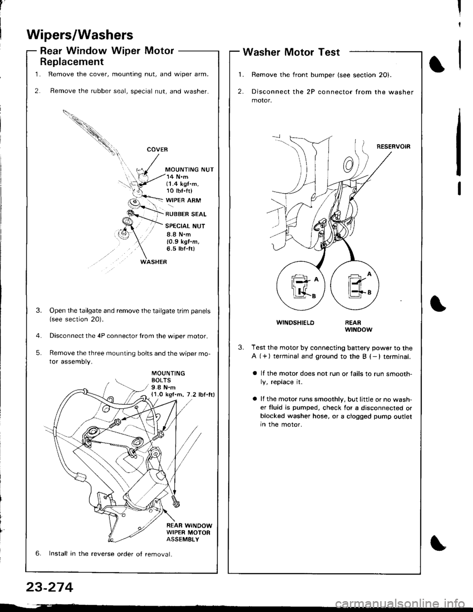
1.
2.
Replacement
Remove the cover, mounting nut, and wiper arm.
Remove the rubber seal, special nut, and washer.
COVEB
MOUNTING NUT
WASHER
14 N'm(1.4 kgt.m,10 tbf.tr)
WIPER ARM
RUBBER SEAL
SPECIAL NUT
8.8 N.m
10.9 kgf.m.6.5 tbf'fr)
MOUNTINGBOLTS9.8 N.m11.0 kgl.m, 7.2 lbl.lrl
REAR WINOOWWIPER MOTORASSEMELY
3.Open the tailgate and remove the tailgate trim panels
{see section 20).
Disconnect the 4P connector trom the wiper motor.
Remove the three mounting bolts and the wiper mo-
tor assembly.
5.
6. Install in the reverse order ot removal.
,'II
t
Wipers/Washers
Rear Window Wiper MotorWasher Motor Test
l�
2.
Remove the front bumper (see section 20).
Disconnect the 2P connector from the washer
motor.
RESERVOIR
1
WINDSHIELDREARwtNDow
3.Test the motor by connecting battery power to the
A (+) terminal and ground to the B (-lterminal.
a lf the motor does not run or fails to run smooth-
ly, replace it.
a lf the motor runs smoothly, but little or no wash-
er fluid is pumped, check for a disconnected orblocked washer hose, or a clogged pump outletIn the motor.
23-274
Page 1330 of 1681
1.
2.
3.
5.
6.
7.
Remove the front bumper (see section 20).
Remove the left front inner fender.
Disconnect the 2P connector and hose from the
washer motor.
Remove the three mounting bolts and the washer
reservotr.
Remove the washer motor lrom the reservoir.
Remove the windshield wiper arms and air scoop(see page 23-272). Then remove the washer nozzles
anq noses.
Install in the reverse order of removal.
NOTE:
a Take care not to pinch the hoses during instal-
ralron.
a Install the cljps firmly.
a After installing, adjust the aim of the washer
nozzles.REAFWINDOWWASHERNOZZLEWINDSHIELDWASHERNOZZLE
MOUNTINGBOLTS9.8 N.m{1.0 kgl.m, 7.2 lbf.ftl
n
V,--"Q
V
n
Washer Replacement
J
J)
)
rnhlF*, ',
23-275
Page 1340 of 1681

Precautions/Procedures
Steering-related Precautions
Steering Wheel and Gable Reel Alignment
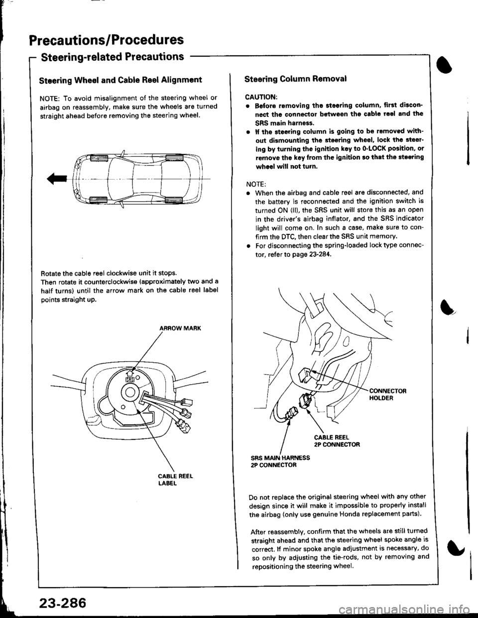
NOTE: To avoid misalignment of the steering wheel or
airbag on reassembly. make sure the wheels are turned
straight ahead before removing the steering wheel.
Rotate the cable reel clockwise unit it stops.
Then rotate it counterclockwise (approximately two and a
half turns) until the arrow mark on the cable reel label
points straight up.
ARROW MARK
23-286
Steering Column Removal
CAUTION:
. Before romoving the steoring column, lirst di3con-
nect ths connector bctwoen tho csble rsal and the
SBS main harneEs.
. lf the steeting column is going to be rsmoved with-
out dismounting the steering wheel, lock the steer-
ing by iurning the ignition k6y to o'LOCK position' or
remove tho key lrom thc ignition ro that the steering
wheel will not turn.
NOTE:
When the airbag and cable reel are disconnected, and
the battery is reconnected and the ignition switch is
turned ON (ll), the SRS unit will store this as an open
in the driver's airbag inflator, and the SRS indicator
light will come on. In such a case, make sure to con-
firm the DTC, then clear the SRS unit memory.
For disconnecting the spring-loaded lock type connec-
tor, refer to page 23-284,
SRS MAIN HARNESS2P CONNECTOR
Do not replace the original steering wheel with any other
design since it will make it impossible to properly install
the airbag {only use genuine Honda replacement parts).
After reassembly. confirm that the wheels are still turned
straight ahead and that the steering wheel spoke angle is
correct, lf minor spoke angle adjustment is necessary, do
so only by adjusting the tie-rods, not by removing and
repositioning the steering wheel.
L
Page 1372 of 1681

Airbag
Replacement (cont'd)
LOWERMOUNTINGNUTS
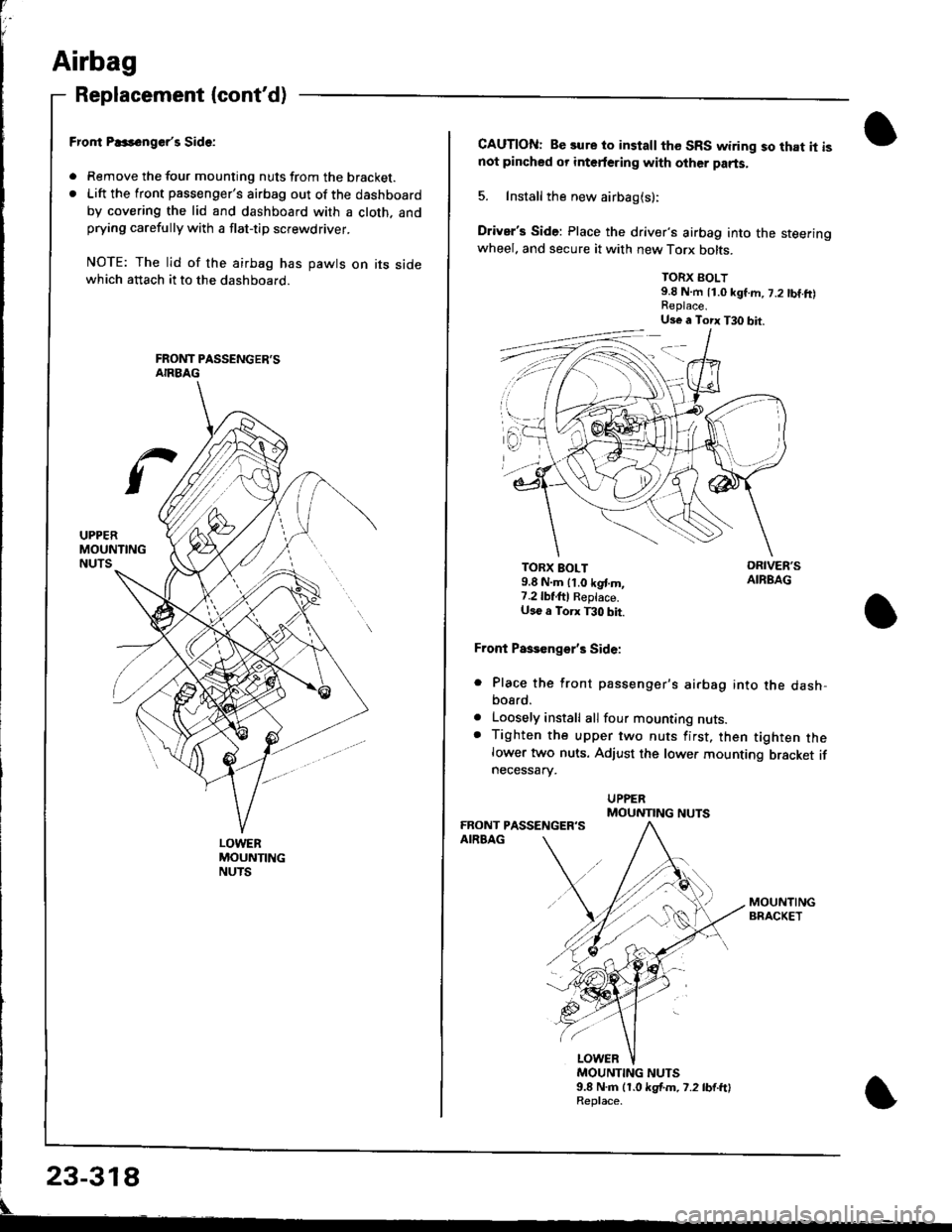
Fror|t P..s6nger'r Side:
. Remove the tour mounting nuts from the bracket.. Lift the front passenger's airbag out of the dashboard
by covering the lid and dashboard with a cloth. andprying carefully with a flat-tip screwdriver.
NOTE: The lid of the airbag has pawts on its sidewhich attach it to the dashboard.
CAUTION: Be sure to install the SRS wiring so that it isnot pincbed or interfering with other parts.
5. Install the new airbag(s):
Driver's Side: Place the driver's airbag into the steeringwheel. and secure it with new Torx bolts.
TORX BOLT9.8 N.m 11.0 kgf.m, 7.2 tbf.ft)
TORX BOLT9.8 N.m lt.o kgt m,7.2lbf,ftl Reptace.U36 a Torx T30 bit.
Front Paseenge/s Side:
Place the front passenger's airbag into the dash,bosrd.
Loosely install all four mounting nuts.Tighten the upper two nuts first, then tighten thelower two nuts. Adjust the lower mounting bracket ifnecessarv.
a
a
MOUNTING NUTS9.8 N.m (1.0 kgf.m. 7.2 lb{.ftlReplace.
Us€ a Torx T30 bit.
MOUNTING NUTS
Page 1374 of 1681

Before scrapping any airbags (including those in a whole
car ro be scrappedl, the airbags must be deployed. lf the
car is still within the warranty period, before you deploy
the airbags, the Acura District Technical Manager mustgive approval and/or special instructions. Only after theairbags have been deployed (as the result of vehicle colli-
sion, for example). can they be scrapped.
lf the airbags appear intact (not deployed). treat themwith extreme caution.
Follow this procedure:
Deploying the Airbags: In"vehicle
NOTE: lf an SRS vehicle is to be entirely scrapped. itsairbags should be deployed while still in the vehicle. Theairbags should not be considered as salvageable parts
and should never be installed in another vehicle.
E@ Contirm that each airbsg is securelymounted; otherwise, severe personal iniury could resultfrom deployment.
1. Disconnect the battery negative cable, then discon-nect the positive cable.
2. Confirm that the special tool is functioning properly
by following the check procedure on the label onthe tool or on page 23-321.
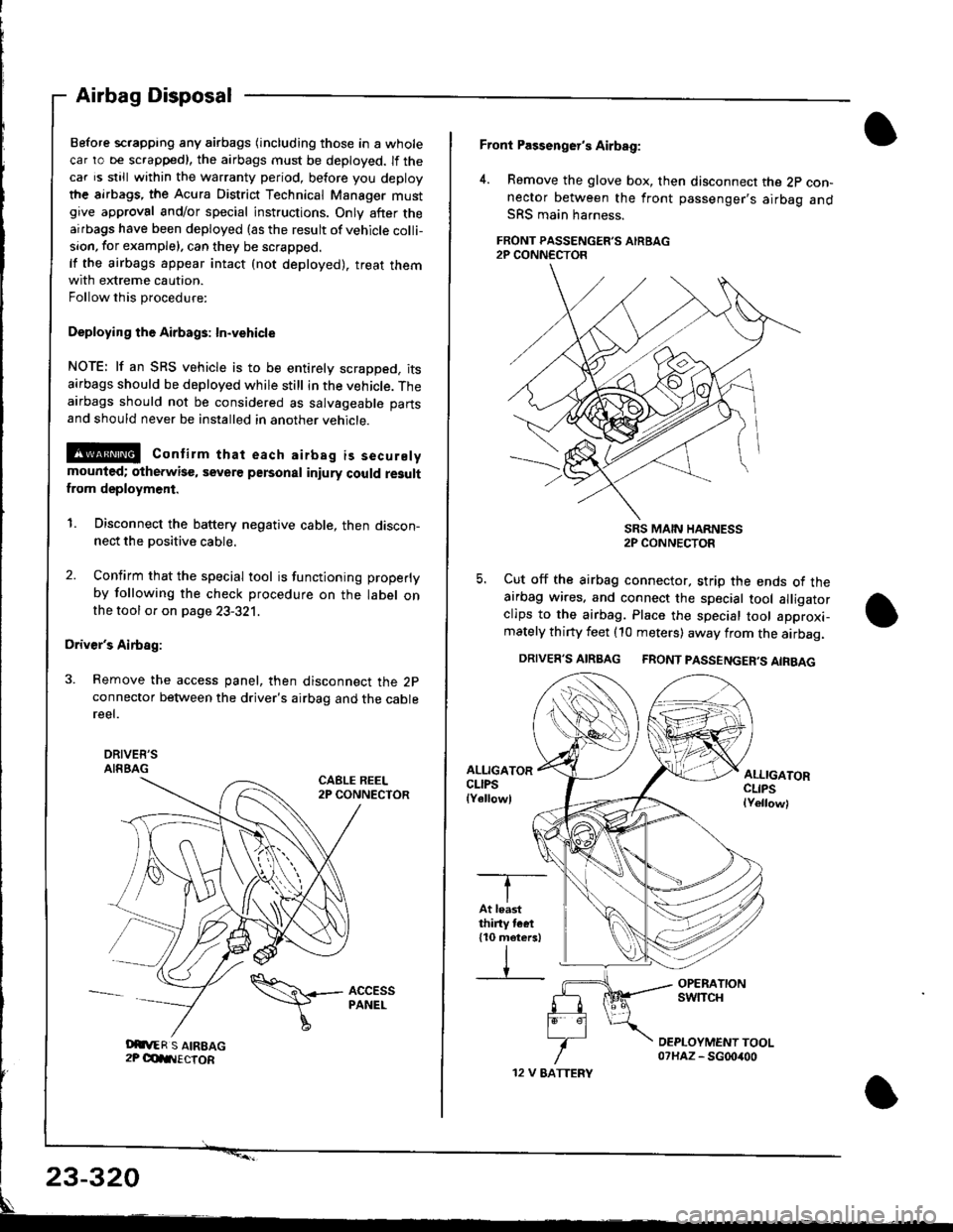
Driver's Airbag:
3. Remove the access panel, then disconnect the 2pconnector between the driver's airbag and the cablereel.
DRIVEE'SAIRBAGCABLE REEL2P CONNECTOR
Airbag Disposal
Oit,ER S AIREAG2P OdIIIECTOR
\\+- AccEss
I
PANEL
12 V EATTERY
Front Passenger's Airbag:
4. Remove the glove box, then disconnect the 2p con-nector between the front passenger's airbag andSRS main harness.
FRONT PASSENGER'S AIRBAG2P CONN€CTOR
SRS MAIN HARNESS2P CONNECTOR
5. Cut off the airbag connector, strip the ends ot theairbag wires. and connect the special tool alligatorclips to the airbag. Place the special tool approxi-mately thirty feet (10 meters) away from the airbag.
DRIVER'S AIRBAG FRONT PASSENGER'S AIRBAG
ALLIGATORCLIPSlYellowl
ALLIGATORCLIPSlYellowl
-T--
IAt leastthiny tcet110 meters)
IV
23-320
Page 1388 of 1681
)a
)a
'ouno ulslnoulron Scnemarlcs -
This samDle Ground Distribution schematic shows all of the components thal share two
ground points.
LEFT RIGHT RIGHTREAR REAR REARLEFT LEFT TURN RTGHT TURN RIGHT SIDEBRAKE LIGHTS/ BACK-UP SIGNAL BACK-UP SIGNAL BRAKE LIGHTS/ MARKER
TAILLTGHTS LIGHT LIGHT LIGHT LIGHT TAILLIGHTS LIGHT
Page110-7 Page110-8 Page110-5 Page110-8 Page110'5 Page110-7 Page110-7
r--r r--t t- t-l t-t ,-t r--r r--t r-\t*-r r--r \./ \/ \./ \/ \/
I LICENSE LIGHTS
I Page 110'6
l"uo, O O
l*"''* L.J
!-.1**
FUELPUMPPage 23-1
lltl
LEFTREARstoEMARKERLIGHTPage 110-7
POWERANTENNAMOTORPage 151
tlll
:E_,
a-al
JL
c549
t\
HIGHMOUNTBRAKELIGHTPage 110-9
ttll
REARwtNDowWIPERMOTORPage 92
tlll
iIn*
a-
Ira
T!. G601
FUEL TANKUNITPages 74and 81
tltl
1 Y C652
irg c530- | puoro tzt
I
106
T+ Gs21
c603
Ground DistributiSchematics
E
)o