1998 HONDA INTEGRA ECU
[x] Cancel search: ECUPage 1083 of 1681
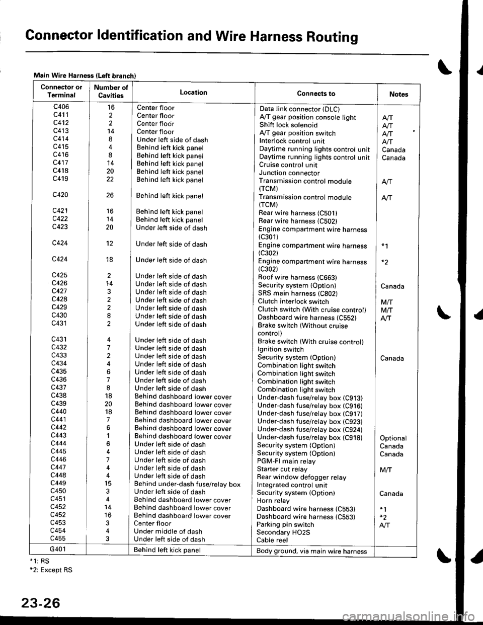
Connector ldentification and Wire Harness Routing
Main Wire Hsfness {Left branch}
Connector ol
TerminalNumber ol
CavitiesLocationConneqts toNot6s
c406
c41 1
c4't2
c413
c414
c415
c416
c417
c4l8
c419
c420
c421
c422
c423
c424
c424
c425
c426
c427
c428
c429
c430
c431
c43'rc432
c433
c434
c435
c436
c431
c438
c439c440
c441
c442
c443
c444
c445
c446
c447
c44ac449
c450
c451
c452
c452
c453
c454c455
16
2
2
14
4
8
14
20
22
26
Center floor
Center floorCenter flodrCenter floorUnder left side of dashBehind Ieft kick panel
Behind left kick panel
Behind left kick panel
Behind left kick panel
Behind left kick panel
Behind left kick panel
Behind left kick panel
Behind left kick panel
Under left side of dash
Under left side of dash
Under left side of dash
Under left side of dashUnder left side of dashUnder left side of dashUnder left side of dashUnder left side of dashUnder left side of dashUnder left side of dash
Under left side of dashUnder left side of dashUnder left side of dashUnder left side of dashUnder left side of dashUnder left side of dashUnder left side of dashBehind dashboard lower coverBehind dashboard lower coverBehind dashboard lower coverBehind dashboard lower coverBehind dashboard lower coverBehind dashboard lower coverUnder leit side of dashUnder left side of dashUnder left side of dashUnder left side of dashUnder left side of dashBehind under-dash fuse/relay boxUnder left side of dashBehind dashboard lower coverBehind dashboard lower coverBehind dashboard lower coverCenter floorUnder middle of dashUnder left side of dash
Data Iink connector (DLC)
A,/T gear position console lightShift lock solenoidAy'T gear position switchInterlock control unitDaytime running lights controlOaytime running lights controlCruise control unitJunction connectorTransmission control module(rcM)
Transmission control module
{TCM)Rear wire harness (C501)
Rear wire harness (C502)
Engine compartment wire harness(c301)
Engine companment wire harness I *1
(c3021 IEngine compartment wire harness(c302) lRoof wire harness {C663} |Security system {Option) | CanaAaSRS main harness (C802) |Clutch interlock switch I VnClutch switch (With cruise control) M/TDashboard wire harness (C552) AlTBrake switch lwithout cruise Icontrol) |Brake switch (With cruise control)lgnition switch ISecurity system {Option) CanadaCombination light switch /Combination light switch ICombination light switchCombination light switchUnder-dash fuse/relay box (C913)
Under-dash fuse/relay box (C916)
Underdash fuse/relay box (C917)
Under-dash fuse/relay box (C923)
Under-dash fuse/relay box (C924) |Under-dash fuse/relay box {C918) I OptionalSecurity system (Option) CanadaSecurity system (Optionl CanadaPGM-Fl main relayStarter cut relay ] M,.fRear window defogger relay IIntegrated control unitSecurity system (Option) CanadaHorn relay
Dashboard wire harness (C553)
Dashboard wire harness {C553) | -2
Parking pin switch I A,"ISecondary HO2S
Cable reel
Afi
I Atr
lf[
unit ] Canadaunit I Canada
16
14
20
't2
ti
I'
li
ll
li
+4
3
G401 Behind teft kick panelBody ground, via main wire harness*1: RS+2: Except RS
23-26
Page 1172 of 1681
)
t
J
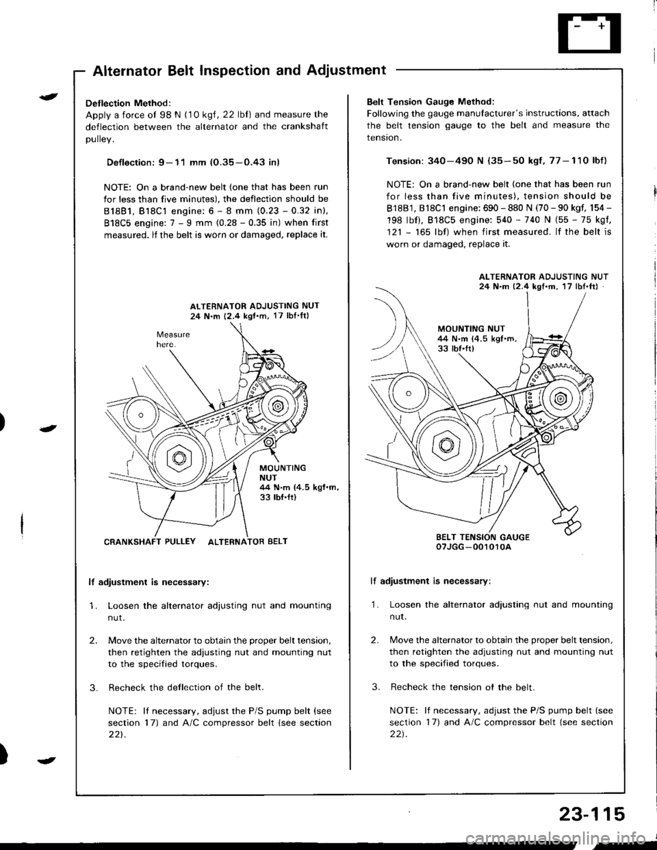
Altelnator ttelr Inspecuon ano Aol
Detlection Method:
Apply a force ol 98 N (1 0 ksl, 22 lbl) and measure the
deflection between the alternator and the crankshaft
DUllev,
Defloction: 9- 11 mm (O.35-O.43 inl
NOTE: On a brand-new belt (one that has been run
for less than five minutes), the deflection should be
81881, Bl8Cl engine: 6 - 8 mm (0.23 - 0.32 inl,
818C5 engine: 7 - I mm (0.28 - 0.35 in) when first
measured, lf the belt is worn or damaged, replace it.
ALTERNATOR ADJUSTING NUT
24 N.m 12,4 kgl.m, 17 lbI'ftl
MOUNTINGNUT44 N.m (4.5 kgf.m,33 tbf.ft)
CRANKSHAFT PULLEY ALTERNATOR BELT
lf adiustment is necessary:
1. Loosen the alternator adjusting nut and mounting
nut.
2.
3.
Move the alternator to obtain the proper belt tension,
then retighten the adiusting nut and mounting nut
to the specified torques.
Recheck the dellection of the belt.
NOTE: lI necessary, adjust the P/S pump belt (see
section 17) and A/C compressor belt (see section
221.
Belt Tension Gauge Method:
Following the gauge manulacturer's instructions, attach
the belt tension gauge to the belt and measure the
tension.
Tension: 340-490 N {35-50 kgf,77-11O lbf)
NOTE: On a brand-new belt (one that has been run
for less than five minutes), tension should be
818B1, 818C1 engine: 690 - 880 N (70 - 90 kgf, 154 -
198 lbf), 818C5 engine: 540 - 740 N (55 - 75 kgf,
121 - 165 lbf) when first measured. lf the belt is
worn or damaged, replace it.
lf adiustment is necessary:
1. Loosen the alternator adjusting nut and mounting
nut.
2.
3.
Move the alternator to obtain the proper belt tension,
then retighten the adjusting nut and mounting nut
to the specified torques.
Recheck the tension ot the belt.
NOTE: It necessary, adjust the P/S pump belt (see
section 17) and A/C compressor belt (see section
22t.
ALTERNATOR ADJUSTING NUT24 N.m 12.4 kgf'm, 17 lbt.ftJ
BELT TENSION GAUGEoTJGG -0010r0A
23-115
J
,-
Page 1204 of 1681
)
t
t
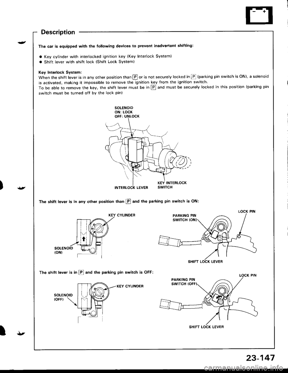
Description
Ths cal is equipped with the tottowing devices to prevent inadvertenl shifting:
a Key cylinder with interlocked ignition key (Key Interlock System)
a shift lever with shift lock (shilt Lock system)
Key Interlock System:
When the shift lever is in any other position than @ or is not securely locked in @ (parking pin switch is ON), a solenoid
is activated, making it impossible to remove the ignition key from the ignition switch.
To be able to remove the key, the shift lever must be in E] and must be securely locked in this position {parking pin
switch must be turned oft by the lock pin)
The shift lever is in any othel position than El and the psrking pin switch is ON:
CYLINDER
The shitt lever is in l!] and the parking pin switch is OFF:
KEY CYLINOER
PARKING PIN
SHIFT LOCK LEVER
SHIFT LOCK LEVER
{t
23-147
Page 1335 of 1681
)
Precautions/Procedures
General Precautions
Carefully inspect any SRS part before you install it,
Do not install any part that shows signs of being drop-
ped or improperly handled. such as dents, cracks or
deformstion:
- Airbags- Cable reel- SRS unit
' Use only a digital multimeter to check the system lf
it's not a Honda multimeter. make sure its output is
10 mA (0.01 A) or less when switched to the smallest
value in the ohmmeter range. A tester with a higher
output could damage the airbag circuit or cause acci-
dental deployment and possible injury.
r Do not install used SRS parts from anothercar.When
making SRS repairs, use only new parts.
r Except when performing electrical inspections,
always disconnect both the negative cable and posl-
tive cable from the batterY, and wait at least three
minutes before beginning work.
r Replacement of the combination light and wiper/
washer switches and cruise control switch can be
done without removing the steering wheel:
- Combination light and wiperlwasher switch replace-
ment (see page 23-268).- Cruise controi sevresume switch replacement (see
page 23-259t�.
. Whenever the ignition switch is ON (ll), or has been
turned OFF for less than three minutes, be caretul not
to bump the SRS unit; the airbags could accidentally
deploy and cause damage or iniuries.
. Whenever the airbag has been activated, replace the
SRS unit.
. The original radio has a coded theft protection circuit.
Be sure to get the customer's code number beJore dis-
connecting the battery cables.
23-281
Airbag Handling and Storage
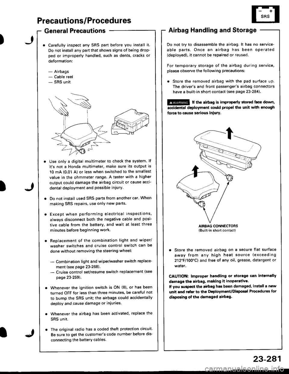
Do not try to disassemble the airbag. lt has no service-
able parts. Once an airbag has been operated
(deployed), it cannot be repaired or reused.
For temporary storage of the airbag during service,
please observe the following precautions:
. Store the removed airbag with the pad surface up.
The driver's and tront passenger's airbag connectors
have 8 built-in short contact (see page 23-284).
@ r the airbag is improp€rly storcd face down,
accidental deployment could propel the unit with enough
force to caus6 serious iniury.
AIRBAG CONNECTORS(Built-in short contact)
. Store the removed airbag on a secure flat surface
away from any high heat source (exceeding
212F110O'CI and free of any oil, grease, detergent or
water.
CAUTION: lmproper handling or storage can intornally
damags the airbag, making it inoperative.
1l you su3pocl the aitbag has been damaged, install a ncw
unit and rofEr to ths Deployment/Dilpolal Procedures for
dbposing of ihe damsged ailbag.
)
Page 1336 of 1681
Precautions/Procedu res
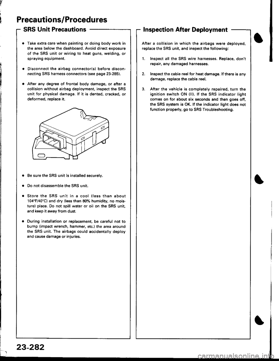
SRS Unit Precautions
Take extra caro when painting or doing body work in
the area below the dashboard. Avoid direct exposure
of the SRS unit or wiring to heat guns, welding, or
spraying equipment.
Disconnect the airbsg connector(s) before discon-
necting SRS harness connectors (see page 23-2851.
After any degree of frontal body damage, or after a
collision without airbag deployment, inspect the SRS
unit for physical damage. lf it is dented, cracked, or
deformed, reDlace it.
Be sure the SRS unit is installed securelv.
Do not disassemble the SRS unit.
Store the SRS unit in a cool (lass than about
104'F/40"C) and dry (less than 80% humidity, no mois-
ture) place, Do not spill water or oil on the SRS unit,
and keeD it awav trom dust.
During installation or r6placement, be careful not to
bump {impact wrench, hammer, etc.) the area around
the SRS unit. The airbags could accidentally deploy
and cause damsge or injuries,
v
Inspection After Deployment
After a collision in which the airbags w6re deployed,
replace the SRS unit, and inspect the following:
1, Inspect all the SRS wire harnesses. Replace, don't
repair, any damaged harnesses
2. Inspect the cable reel for heat damage. lf there is any
damage. replace the cable reel.
3. After the vehicle is completely repairod, turn the
ignition switch ON {ll). lf the SRS indicator light
comes on for about six seconds and then goes off,
the SRS system is OK. lf the indicator light does not
function properly. go to SRS Troubleshooting.
23-282
Page 1337 of 1681
)J
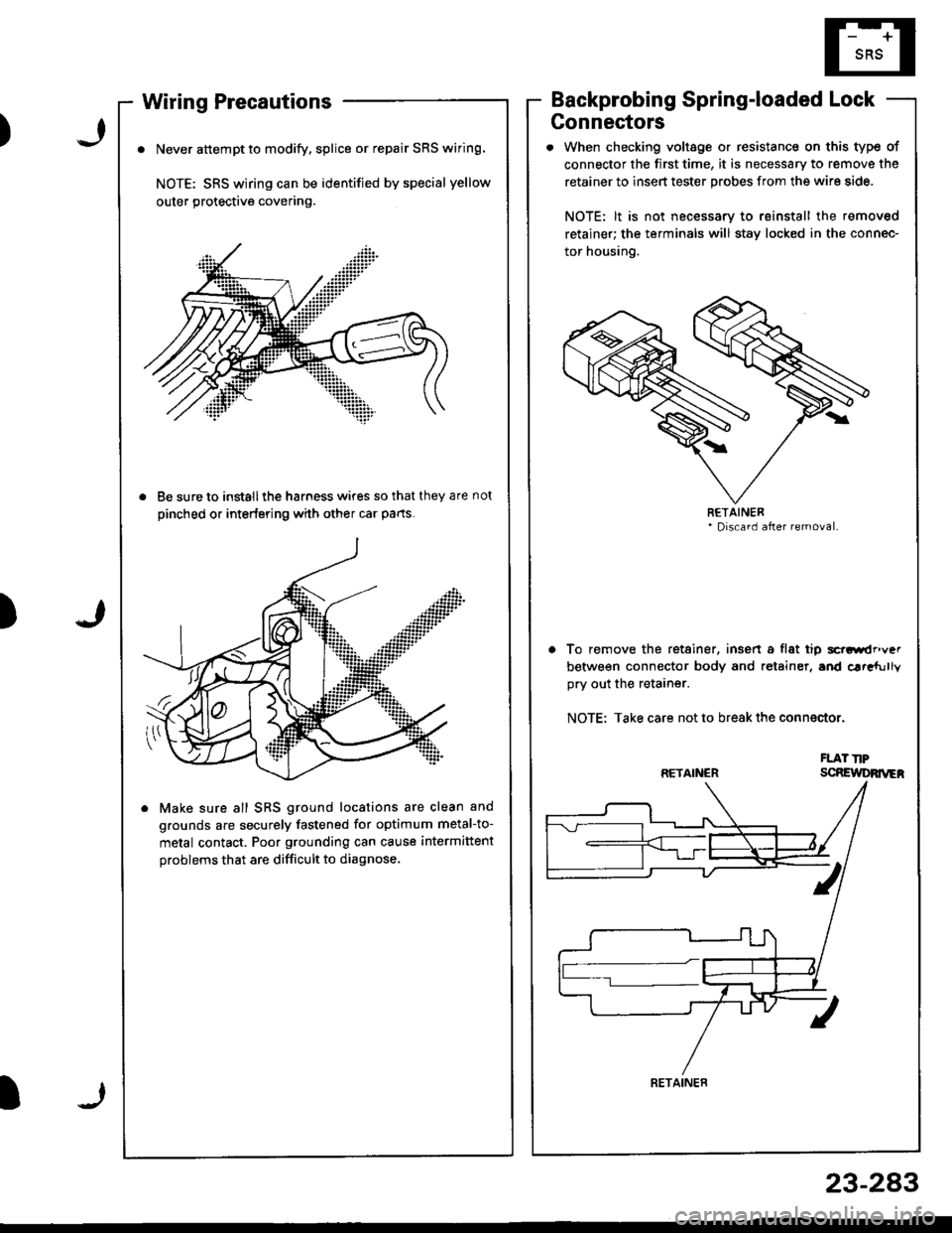
Wiring Precautions
. Never attempt to modify, splice or repair SRS wiring.
NOTE: SRS wiring can be identified by special yellow
outer protective covering.
. Be sure to install ihe harness wires so that they are not
pinched or interfering with other car parts.
. Make sure all SRS ground locations are clean and
grounds are securely fastened for optimum metal-to-
metal contact. Poor grounding can cause intermittent
problems that are difficult to diagnose.
Backprobing Spring-loaded Lock
Connectors
. When checking voltage or resistance on this type of
connector the first time, it is necessary to remove the
retainer to insert tester probes from the wire side.
NOTE: lt is not necessary to reinstall the removed
retainer; the terminals will stav locked in the connec-
tor housing.
To remove the retainer, insen a flat tip scrGirdr'\/".
between connector body and retainer, and car"fully
ory out the retarner.
NOTE: Take care not to break the conn€ctor.
FLAT TIPscRElt DRrrrEh
)
RETAINER
RETAINER
RETAINER
23-283
Page 1343 of 1681
)
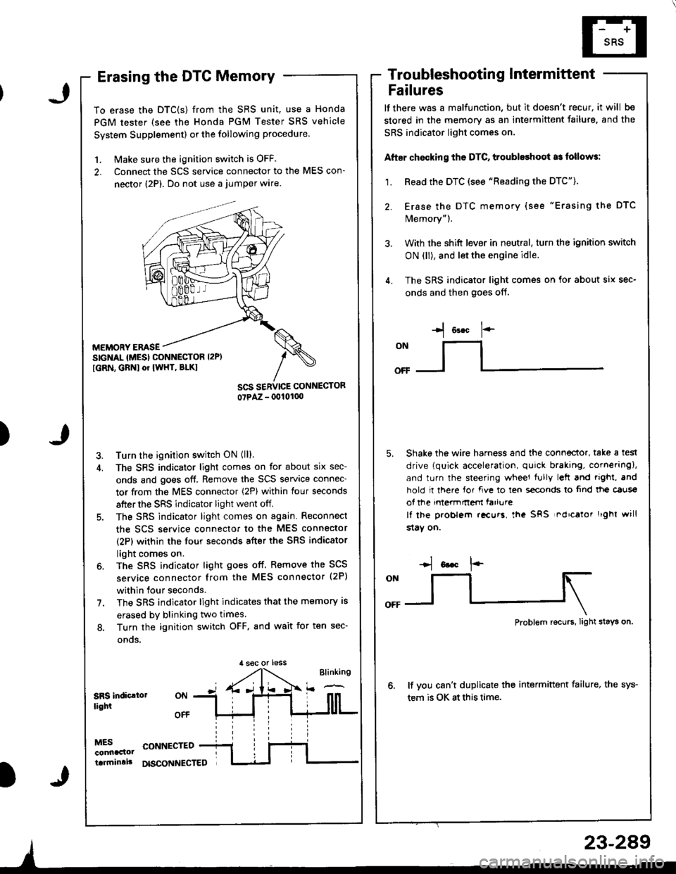
Erasing the DTC Memory
To erase the DTC(S) from the SRS unit, use a Honda
PGM tester (see the Honda PGM Tester SRS vehicle
System Supplement) or the following procedure.
1. Make sure the ignition switch is OFF.
2. Connect the SCS service connector to the MES con-
nector (2P). Do not use a jumper wlre.
MEMORY EMSESIGNAL {MESI CONNESTOR I2P)
[GRN, GBNI or IWHT, BLKI
Turn the ignition switch ON (ll).
The SBS indicator light comes on for about six sec-
onds and goes off. Remove the SCS service connec-
tor from the MES connector (2P) within four seconds
after the SRS indicator light went off.
The SRS indicator light comes on again. Reconnect
the scs service connector to the MES connector
(2P) within the four seconds after the SRS indicator
light comes on.
The SRS indicator light goes off. Remove the SCS
service connector from the MES connector (2P)
within four seconds.
The SRS indicator light indicates that the memory is
erased by blinking two times.
Turn the ignition switch OFF. and wait for ten sec-
onos.
Troubleshootin g Intermittent
Failures
lf the.e was a malfunction, but it doesn't recur, it will be
stored in the memory as an intermittent failure, and the
SRS indicator light comes on,
Atter chocking ths DTC, troubleshoot as follows:
1. Read the DTC (see "Reading the DTC").
2. Erase the DTC memory (see "Erasing the DTC
Memory").
3. With the shift l€ver in neutral, turn the ignition switch
ON (ll), and let the engine idle.
4. The SRS indicator light comes on for about six sec-
onds and then goes off.
I o"* 1--
ONllI
Shake the wire harness and the connector, take a test
drive (quick acceleration, quick braking, cornering),
and turn the steering wheel fully left and righi, and
hold I there for fve to ten s€conds lo 6nd tt|e caus€
of the intermnem farlure
It lhe problem .!curs, lha SRS nd'calor r'ghl will
$aY on.
,l soc or less
Problem recurs, Iight stays on
lf vou can't duplicate the intermittent failure, the sys-
tem is OK at this time.SRS indic.lollight
MESconnaclottarrninlll
CONNECTED
DISCONNECTED
23-289
Page 1372 of 1681
Airbag
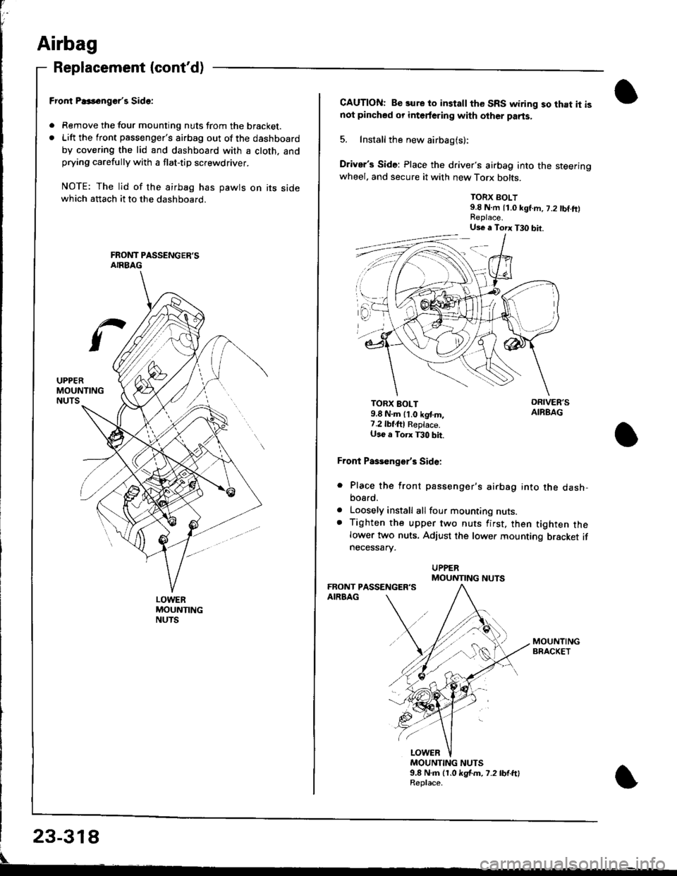
Replacement (cont'd)
LOWERMOUNTINGNUTS
Fror|t P..s6nger'r Side:
. Remove the tour mounting nuts from the bracket.. Lift the front passenger's airbag out of the dashboard
by covering the lid and dashboard with a cloth. andprying carefully with a flat-tip screwdriver.
NOTE: The lid of the airbag has pawts on its sidewhich attach it to the dashboard.
CAUTION: Be sure to install the SRS wiring so that it isnot pincbed or interfering with other parts.
5. Install the new airbag(s):
Driver's Side: Place the driver's airbag into the steeringwheel. and secure it with new Torx bolts.
TORX BOLT9.8 N.m 11.0 kgf.m, 7.2 tbf.ft)
TORX BOLT9.8 N.m lt.o kgt m,7.2lbf,ftl Reptace.U36 a Torx T30 bit.
Front Paseenge/s Side:
Place the front passenger's airbag into the dash,bosrd.
Loosely install all four mounting nuts.Tighten the upper two nuts first, then tighten thelower two nuts. Adjust the lower mounting bracket ifnecessarv.
a
a
MOUNTING NUTS9.8 N.m (1.0 kgf.m. 7.2 lb{.ftlReplace.
Us€ a Torx T30 bit.
MOUNTING NUTS