1998 HONDA CR-V actuator
[x] Cancel search: actuatorPage 51 of 1395
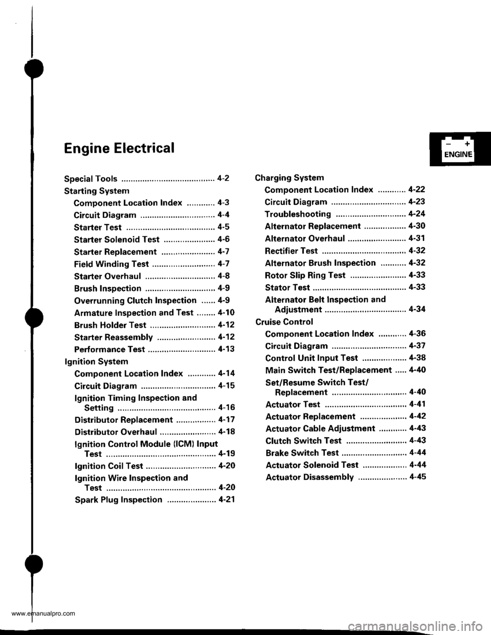
Engine Electrical
Speciaf Tools ............. 4-2
Starting System
Component Location Index ............ 4-3
Circuit Diagram ................................ 4-4
Starter Test ........... 4-5
Starter Solenoid Test ...................... 4'5
Starter Replacement ....................... 4-7
Field Winding Test ........................... 4-7
Starter Overhaul ............................,. 4-8
Brush Inspection ...........................,., 4-9
Overrunning Glutch Inspection ...... 4-9
Armature lnspection and Test ........4-10
Brush Holder Test ............................ 4-12
Starter Reassemb|y ......................... 4-1 2
Perf ormance Test ............................. 4- 1 3
lgnition System
Component Location Index ............ 4-14
Circuit Diagram ................................ 4-15
lgnition Timing Inspection and
Setting .......................................... 4-16
Distributor Replacement ........,........ 4-17
Distributor Overhaul .............,,......... 4-18
lgnition Control Module (lCM) Input
Test ..............................,................ 4-19
fgnition Coil Test .............................. 4-2O
lgnition Wire Inspection and
Test ............................................... 4-20
Spark Plug Inspection ..................... 4-21
-+
ENGINE
Charging System
Component Location Index ............ 4-22
Circuit Diagram ....................,........... 4-23
Troubleshooting .............................. 4-24
Alternator Replacement ..........,....... 4-30
Alternator Overhaul .......,,................ 4-31
Rectifier Test .........4-32
Alternator Brush Inspection ........... 4-32
Rotor Slip Ring Test ........................ 4-33
Stator Test ............. 4-33
Alternator Belt Inspection and
Adiustment ........4-34
Gruise Control
Component Location Index .,,,........ 4-36
Circuit Diagram ................................ 4-37
Control Unit Input Test ................... 4-38
Main Switch Test/Replacement ..... 4-40
Set/Resume Switch Test/
Replacement .......................,........ 4'40
Actuator Test ....,,., 4-41
Actuator Replacement ...............,.... 4-42
Actuator Cable Adiustment ............ 4-43
Clutch Switch Test .......................... 4-43
Brake Switch Test .................. .......... 4-44
Actuator Solenoid Test .............. ...,. 4-44
Actuator Disassembly ..................... 4-45
www.emanualpro.com
Page 86 of 1395
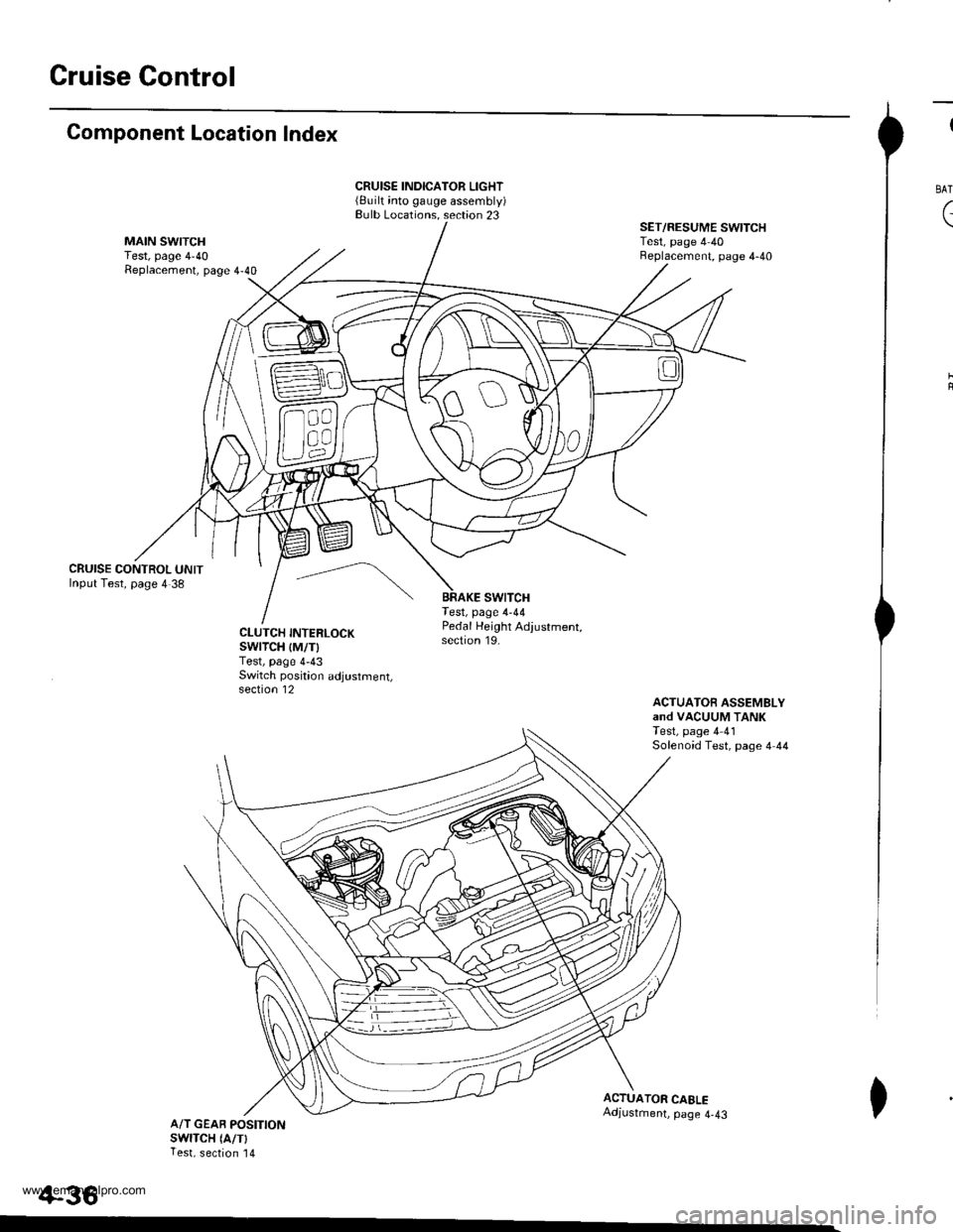
Gruise Control
Component Location Index
CRUISE CONTROL UNITInput Test, page 4 38
CRUISE INDICATOR LIGHT(Built into gauge assembly)Bulb Locations. section 23
swtTcHTest, page 4-44
SET/RESUME SWITCHTest, page 4 40Beplacement, page 4-40
ACTUATOfi ASSEMBLYand VACUUM TANKTest, page 4 41Solenoid Test, page 4 44
CLUTCH INTERLOCKswrTcH {M/T)Test, page 4-43Switch poskion adjustment,section 12
Pedal Height Adjustment,section 19.
ACTUATOR CAELEAdjustment, page 4-43A/T GEAB POSITIONswlTcH (A/TlTest, section '14
+36
I
BAT
(
I
www.emanualpro.com
Page 87 of 1395
UNDER.OASH FUSARELAY BOX
INDICATORLIGHT(0.84W)
lPIOSET
526712813
CRUISE CONTROT UNLT 10
11114
COMEINATONL GH'I SWITCH
f7
IRED/BLK
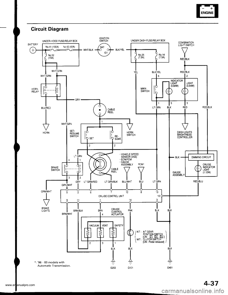
Gircuit Diagram
*: '98 00 models withAutomatic Transmission.
J
BRAK€LGHTSPNK BLK BLK
I L_l
tl
4F /lr,mcern I I
Y{"^ i?tr'.flffi'JF ) l
I
t loN : Pedar rereasedl /l
8LK BLK
TI
G101 G401
CRUISECONTROLACTUATOR
t'BLK
n:
G202
IGNIT ONSWITCHUNDER.HOOD FUSEi RELAY BOX
No 41 (100A) No 42 (404)
4-37
www.emanualpro.com
Page 89 of 1395

Disconnest the lilP connector from the control unit.
Csvity WireTest condition
R€conn€ct tho 14P connGctor to the control unit.
Test: Desired resultPossible cause it result is not obtained
BRNAr'VHTUnder all conditionsCheck for resistance to groundl
There should be 80 - 120 o.
Faulty actuator solenoid
Poor ground (G202)
An open in the wire1BRNUnder all conditionsCheck for resistance to groundl
There should be 40 - 60 0.
11BRN/BLKUnder all conditionsCheck for resistance to ground:
There should be 70 - 110 O.
2GRY
lgnition switch ON (ll),
main switch ON and
brake pedal depressed,
then released
Check for voltage to ground:
There should be 0 V with the pedal
depressed and battery voltage with
the pedal released.
. Faulty brake switch. An open in the wire
BLKUnder all conditionsCheck for continuity to ground:
There should be continuity.
. Poor ground (G401). An open in the wire
5GRNMHT
Brake pedal depressed,
then released
Check for voltage to ground:
There should be battery voltage with
the pedal depressed, and 0 V with
the pedal released.
Blown No.52 1'15 Alfuse in the
under-hood fuse/relay box
Faulty brake switch
An open in the wire
LT GRN/
RED
Set button pushedCheck for voltage to ground:
There should be battery voltage.Blown No. 52 {'15 A} fuse in the
under-hood fuse/relay box
Faulty horn relay
Faulty sevresume switch
Faulty cable reel
An open in the wire7LT GRN/
BLK
Resume button pushed
10RED/BLU
lgnition switch ON lll)Attach to ground:
Cruise indicator light in the gauge
assembly should come on.
Elown bulbBlown No. 25 (7.5 A) tuse in theunder-dash fuse/relay box
Faulty dimming circuit in the gauge
assembly
An open in the wire
ELU^r'r'HT
lgnitjon switch ON {ll}and main switch ON;
raise the front of the
vehicle, block one wheel
and rotate the other
wheel slowly.
Check for voltage between the
ELUA/VHT @ and BLK O terminalsl
There should be 0 - 5 V or more-0 - 5 V or more repeatedly.
Faulty vehicle speed sensor (VSS)
An open in the wire
r3LT GRN
lgnition switch ON {ll}and main switch ONCheck for voltage to ground:
There should be battery voltage.
Blown No. 14 (7.5 A) fuse in theunder-dash fuse/relay box
Faulty main switch
An open in the wire
l4PNK
A'/T: Shift lever in E, EotE
lvl/T: Clutch pedal
releaseo
Check for continuity to ground:
There should be continuity.NOTE: There should be no continu-
ity when the shift lever is in otherpositions or when the clutch pedal is
oepresseo.
Faulty A/f gear position switch 1A,/TlFaulty or misadjusted clutch switch
fi{/r)Poor ground (G101)
An open in the wire
BLU
Start tho engine. turnthe main switch ON, anddrive the vehicle over 25
mph (40 km/h)with the
crurse control set
Check for voltage to ground:
There should be approx.5 V
. Faulty cruise control unit. Shod to ground
*: '98 - 00 models with Automatic Transmission.
4-39
www.emanualpro.com
Page 91 of 1395
n-
n-
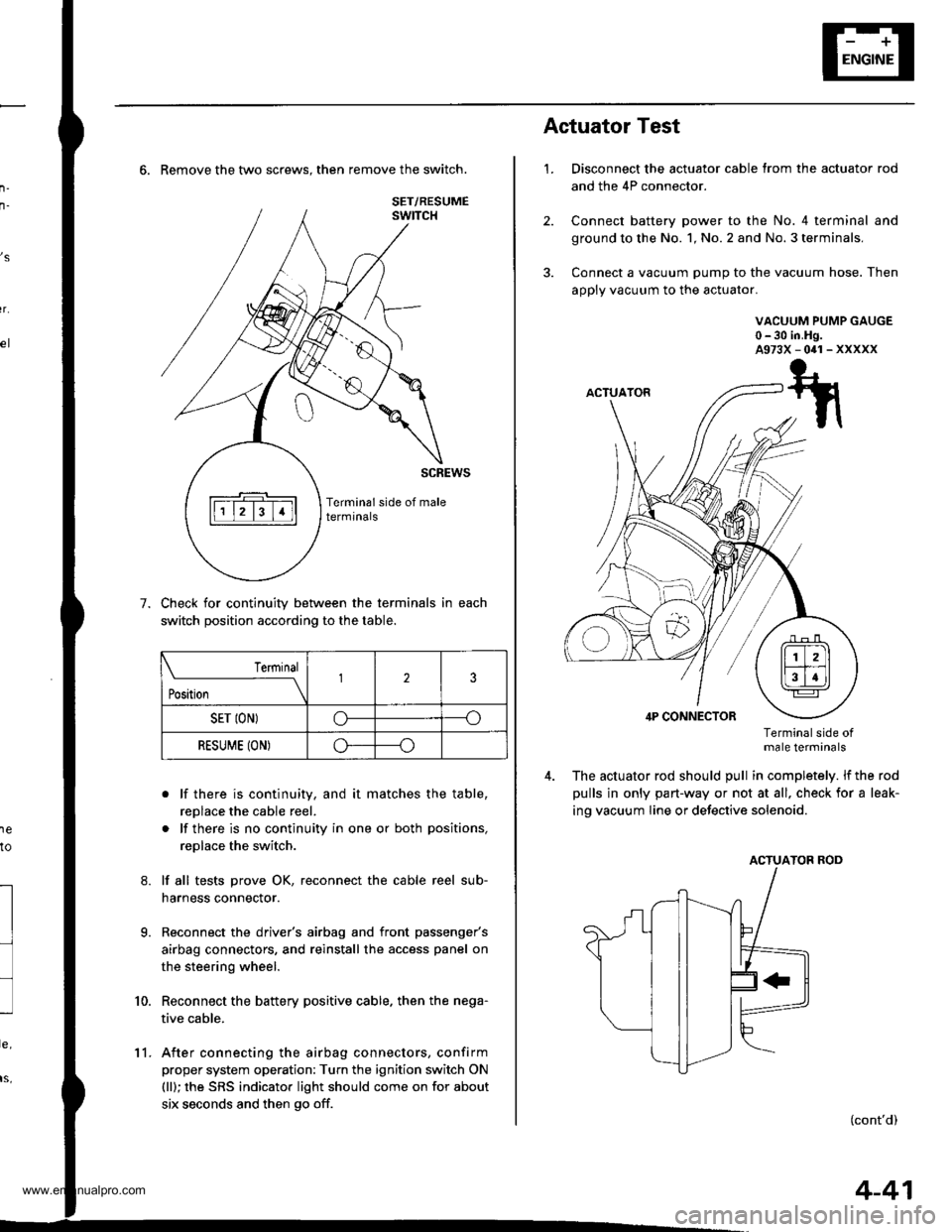
6. Remove the two screws. then remove the switch.
Check for continuity between the terminals in each
switch position according to the table.
. lf there is continuity, and it matches the table,
replace the cable reel.
. lf there is no continuity in one or both positions,
replace the switch.
lf all tests prove OK, reconnect the cable reel sub-
harness connector.
Reconnect the driver's airbag and front passenger's
airbag connectors, and reinstall the access panel on
the steering wheel.
Reconnect the battery positive cable. then the nega-
tive cable.
After connecting the airbag connectors, confirm
proper system operation: Turn the ignition switch ON
(ll); the SRS indicator light should come on for about
six seconds and then go off.
,s
r.
1e
to
7.
l
9.
10.
SET/RESUME
Terminal
t*,r*
-__\l23
SET ION)o----o
RESUME (ON)o----o
11.
4-41
1.
Actuator Test
Disconnect the actuator cable trom the actuator rod
and the 4P connector.
Connect battery power to the No. 4 terminal and
ground to the No. 1, No. 2 and No. 3 terminals,
Connect a vacuum pump to the vacuum hose. Then
apply vacuum to the actuator.
VACUUM PUMP GAUGE0-30 in.Hg.A973X-041-XXXXX
Terminalside otmale terminals
The actuator rod should pull in completely. lf the rod
pulls in only part-way or not at all, check for a leak-
ing vacuum Iine or defective solenoid.
ACTUATOB ROD
(cont'd)
www.emanualpro.com
Page 92 of 1395
Cruise Gontrol
Actuator Test (cont'dl
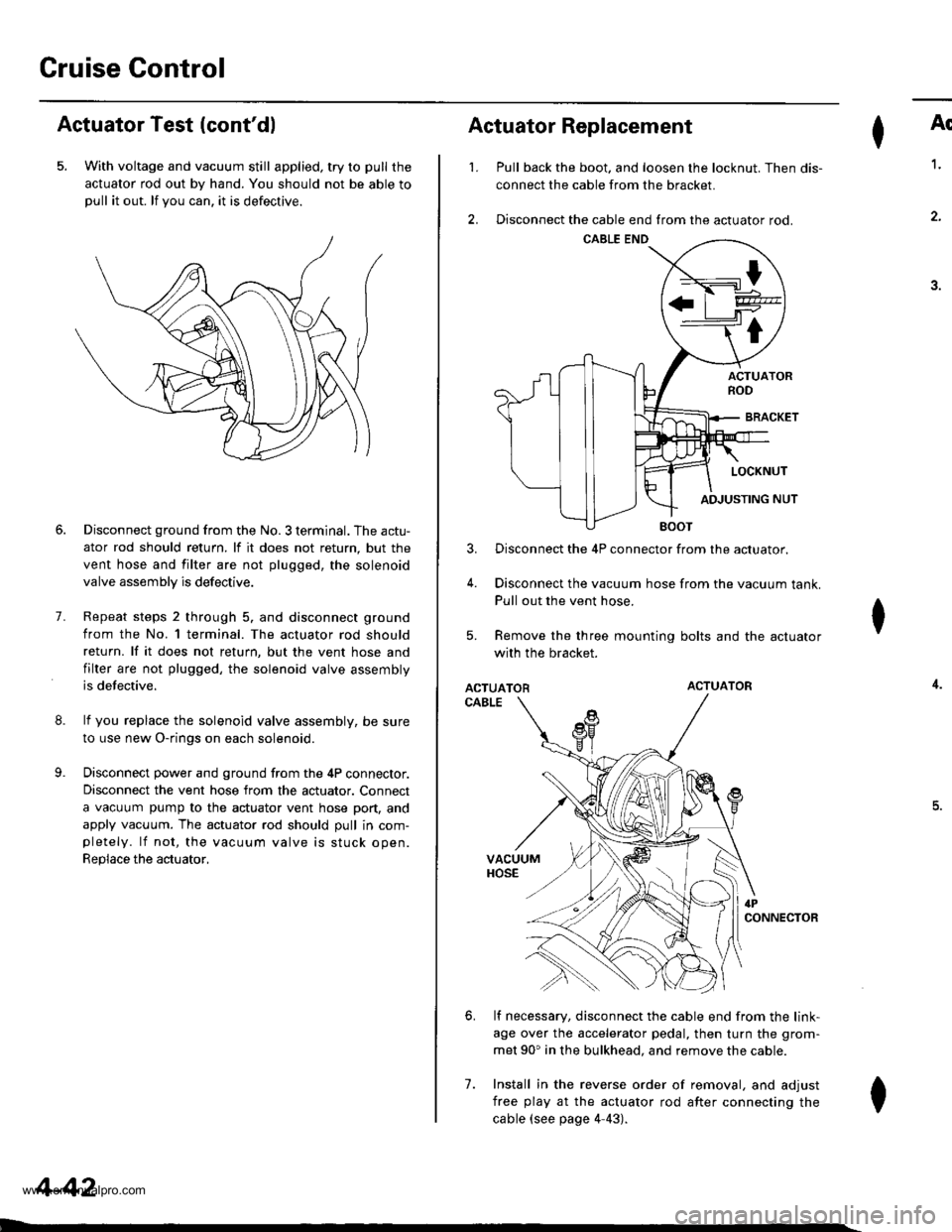
5. With voltage and vacuum still applied, try to pull the
actuator rod out by hand. You should not be able topull it out. lf you can. it is defectrve.
8.
9.
7.
Disconnect ground from the No. 3 terminal. The actu-
ator rod should return. lf it does not return, but the
vent hose and filter are not plugged, the solenoid
valve assembly is defective.
Repeat steps 2 through 5. and disconnect ground
from the No. l terminal. The actuator rod should
return. lf it does not return, but the vent hose and
filter are not plugged, the solenoid valve assembly
is defective.
lf you replace the solenoid valve assembly, be sure
to use new O-rings on each solenoid.
Disconnect power and ground from the 4P connector.
Disconnect the vent hose from the actuator. Connect
a vacuum pump to the actuator vent hose port, and
apply vacuum. The actuator rod should pull in com-pletely. lf not, the vacuum valve is stuck open.
Replace the actuator,
4-42
I
't.
Actuator Replacement
3.
4.
7.
Ar
Pull back the boot. and loosen the locknut. Then dis-
connect the cable from the bracket.
Disconnect the cable end from the actuator rod.
1.
4.
.J.
Disconnect the 4P connector from the actuator.
Disconnect the vacuum hose from the vacuum tank.
Pull out the vent hose.
Remove the three mounting bolts and the actuator
with the bracket.
ACTUATORACTUATOR
CABLE
lf necessary, disconnect the cable end from the link-
age over the accelerator pedal, then turn the grom-
met 90' in the bulkhead. and remove the cable.
Install in the reverse order of removal, and adjust
free play at the actuator rod after connecting the
cable (see page 4-43).
I
6.
I
www.emanualpro.com
Page 93 of 1395
Actuator Cable Adiustment
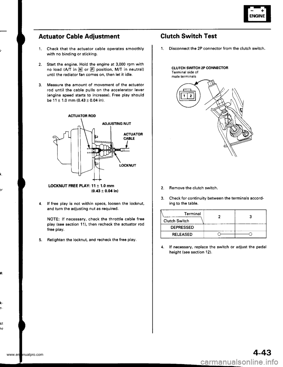
'1.Check that the actuator cable operates smoothly
with no binding or sticking.
Start the engine. Hold the engine at 3,000 rpm with
no load (A,/T in E or E position, M/T in neutral)
until the radiator fan comes on, then let it idle.
Measure the amount of movement of the actuator
rod until ths cable pulls on the accelerator lever
(engine speed starts to increase). Free play should
be 11 t 1.0 mm (0.43 i 0.04 in).
LOCKNUT FREE PLAY: 11 t 1.0 mm
10.43 r 0.04 in)
lf free play is not within specs, loosen the locknut,
and turn the adjusting nut as requirsd,
NOTE: lf necessary, check the throttl€ cable frso
play (s€e section 11), then recheck the actuator rod
free play.
Retighten the locknut, and recheck the free play.
st
te
ACTUATOR ROD
Clutch Switch Test
1. Disconngct ths 2P connector from the clutch switch.
CLUTCH SWITCH 2P CONNECTORTerminalside ofmale terminals
2.
5.
Remove the clutch switch,
Check for continuity between the terminals accord-
ing to the table.
4. lf necessary, replace the switch or adjust the pedal
height (see section t2).
Terminal
Clutch Switch \
OEPRESSED
RELEASEDoo
4-43
www.emanualpro.com
Page 94 of 1395
Cruise Control
Brake Switch Test
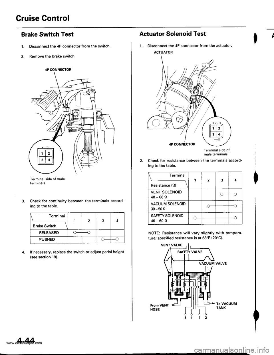
1. Disconnect the 4P connector from the switch,
2. Remove the brake switch.
Terminal side of maletermtnals
Check for continuity between the terminals accord-
ing to the table.
lf necessary, replace the switch or adjust pedal height
(see section 19).
{P CONNECTOR
Terminal
;;;;-t
15
RELEASEDO----o
PUSHEDo--o
4-44
ACTUATOR
Actuator Solenoid Test
1. Disconnect the 4P connector from the actuator.
Terminalside ofmale terminals
Check for resistance between the terminals accord-
ing to the table.
NOTE: Resistance will vary slightly with tempera-
ture; specified resistance is at 68"F (20"C).
VALVE
I
I
I
To VACUUMTANK
Terminal
il',",""*(t)
_\13
VENT SOLENOID
40-600o--o
VACUUM SOLENOIDo---o
30-500
SAFEW SOLENOID
40-600o----o
VACUUM
www.emanualpro.com