Page 36 of 1395
to
l
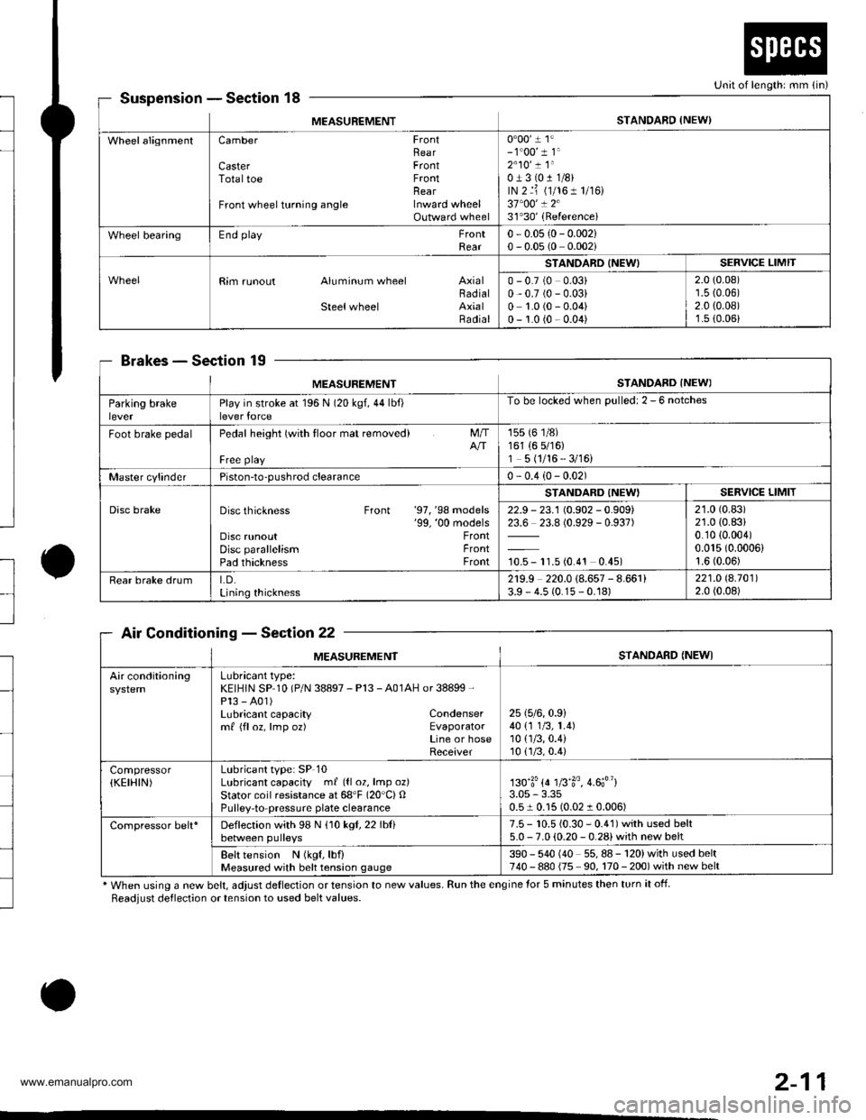
SuspensionSection 18
BrakesSec'tion 19
Air ConditioningSection 22
* When using a new belt, adjust deflection or tension to new values. Run the engine for 5 minutes then turn it off.
Readjust deflection or tension to used belt values.
o
Unit of length: mm {in)
MEASUREMENTSTANDARD {NEW)
WheelalignmentCamber FrontRearCaster FrontTotaltoe FrontnearFront wheel turning angle Inward wheelOutward wheel
0"00' 1 1'- 1"00' 1 1'2"10' ! 1"0J3(011/8)rN 2 ri (1/161 1/r6)37"00' ! 231'30'(Referencei
Wheel bearingEnd playFrontRear0 - 0.05 {0- 0.002}0 - 0.05 (0 0.002i
Rim runout Aluminum wheel AxialBadialSteelwheel AxialRadial
STANOARD (NEW)SERVICE LIMIT
0 - 0.7 (0 0.03)0,0.7 (0 - 0.03)0 1.0 (0 - 0.04)0 - 1.0 {0 - 0.04)
2.0 (0.08)'r.5 {0.06)2.0 {0.08)1.s (0.06)
MEASUREMENTSTANDARD INEWI
Parking brakeleverPlay in stroke at 196 N (20 kgf,44lbf)lever force
To be locked when Dulled: 2 - 6 notches
Foot brake pedalPedal height (with tloor mat removed)
Free playNT
155 (6 1/8)161 (6 5/16)1 5 (1/16 - 3/16)
Master cylinderPiston-to-pushrod clearance0 - 0.4 (0- 0.02)
Disc brakeDisc thickness Front '97, '98 models'99, '00 modelsDisc runoutDisc parallelismPad thickness
FrontFrontFront
STANDARD {NEW'SERVICE LIMIT
22.9 - 23.1 (0.902 - 0.909)23.6 23.8 (0.929 - 0.937)
10.5 - 11.5 (0.4't 0.45)
21.0 (0.83)
21.0 (0.83)
0.10 {0.004)0.015 (0.0006)
1.6 (0.06)
Rear brake drumLD.Lining thickness
2r9.9 220.0 (8.657 - 8.661)3.9 - 4.5 (0.15 - 0.18)221.O 8.70112.0 (0.08)
MEASUREMENTSTANDARD {NEWI
Air conditioningLubricant type:KEIHIN SP 10 (P/N 38897 - Pl3 - A01AH or 38899 -
Pl3 - A01)Lubricant capacity Condensermf {floz, lmp oz) EvaporatorLine or hoseReceiver
25 (5/6,0.9)
40 {1 1/3, 1.4)10 {1/3,0.4)10(.]/3,0.4)
Compressor(KEIHIN)Lubricant type: SP 10Lubricant capacity ml ({l 02, lmp oz}Stator coil resistance at 68'F (20"C) OPulley-to-pressuae plate clearance
130'3'{4 1fi'3o, 4.6;"}3.05 - 3.350.51 0.15 (0.02 1 0.006)
Compressor belt*Deflection with 98 N (10 kgl,22lblibetween pulleys7.5 - 10.5 {0.30 - 0.41) with used belt5.0 - 7.0 (0.20 - 0.28) with new belt
Belt tension N (kgf, lbf)Measured with belt tension gauge390 - 540 (40 55,88-120)withusedbelt740 - 880 {75 90, 170 - 200) with new belt
2-11
www.emanualpro.com
Page 96 of 1395
Engine
Engine RemovaUlnstallation ................ 5-1
Cylinder Head/Valve Train ................... 6-1
Engine Bfock .......... ...........7-1
Engine Lubrication ...........8-1
Intake Manifold/Exhaust System ........ 9-1
Cooling ......... 10-1
www.emanualpro.com
Page 149 of 1395
lllustrated lndex
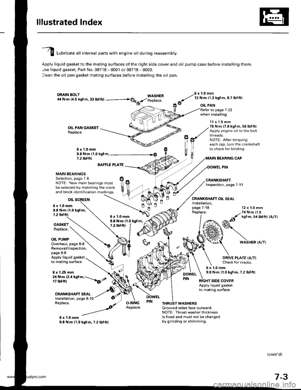
I Luori""t" "tl internal parts with engine oil during reassembly.
Apply liquid gasket to the mating surfaces of the right side cover and oil pump case before installing them.
Jse liquid gasket, Part No. 08718 - 0001 or 08718 - 0003.
:lean the oil pan gasket mating surfaces before installing the oil pan.
WASHERReplace.
76 x 1.0 mm
y' t:n- l.zxstm, 8.7 lbl ftl
9 oIL PAN
OIL PAN GASKETReplace.
to page 1-22when installing
BEARING CAP
OOWEL PIN
CRANKSHAFT OIL SEAL
11x 1.5 mm76 N.m {7.8 kgl.m, 56 lbf.ft}Appiy engine oilto the boltthreaos.NOTE: After lorquingeach cap, turn the crankshaftto check for binding.6x1.0mm9,8 N.m (1,0 kgf.m,7 .2 tbt.lrl
n
MAIN BEARINGSSelection, page 7 8NOTE: New main bearings mustbe selected by matching the crankand block identification markings.
otL
6 x'1.0 mm9.8 N.m {1.0 kgtm,7.2 tbf.ftl
BAFFI.f PLATE
9.8 N.m 11.0 kgt m,7.2 tbt+tl
12 x 1.0 mm
/,71N n 17 .5
&it ks{ m 5a lbtft) {a/Tl
GASKETReplace.
OIL PUMP
Installation,page 7-19Replace.
ln
6WASHER IA/T}Overhaul, page 8-8Removal/lnspection,page 8-9Apply liquid gasketto mating surface.
8 x 1.25 mm
ORIVE PLATE IA/T)Check for cracks.
6x1.0mm9.8 N.m 11.0 kgt.m,7.2 lbtft)2a N.m (2.a kgt.m,---\6/
CRANIGHAFT SEALInstallation, page 8-10Replace-
6x1.0mm9.8 N.m l'1.0 kgf.m,7.2 lbf.ft)
RIGHT SIDE COVERApply liquid gasketto mating surface,
O.RINGReplace.THRUST WASHERSGrooved sides face outlvard,NOTE: Thrust washer thicknessis lixed and must not be changedby grinding or shimming.
(cont'd)
7-3
6x1.0mm
www.emanualpro.com
Page 165 of 1395
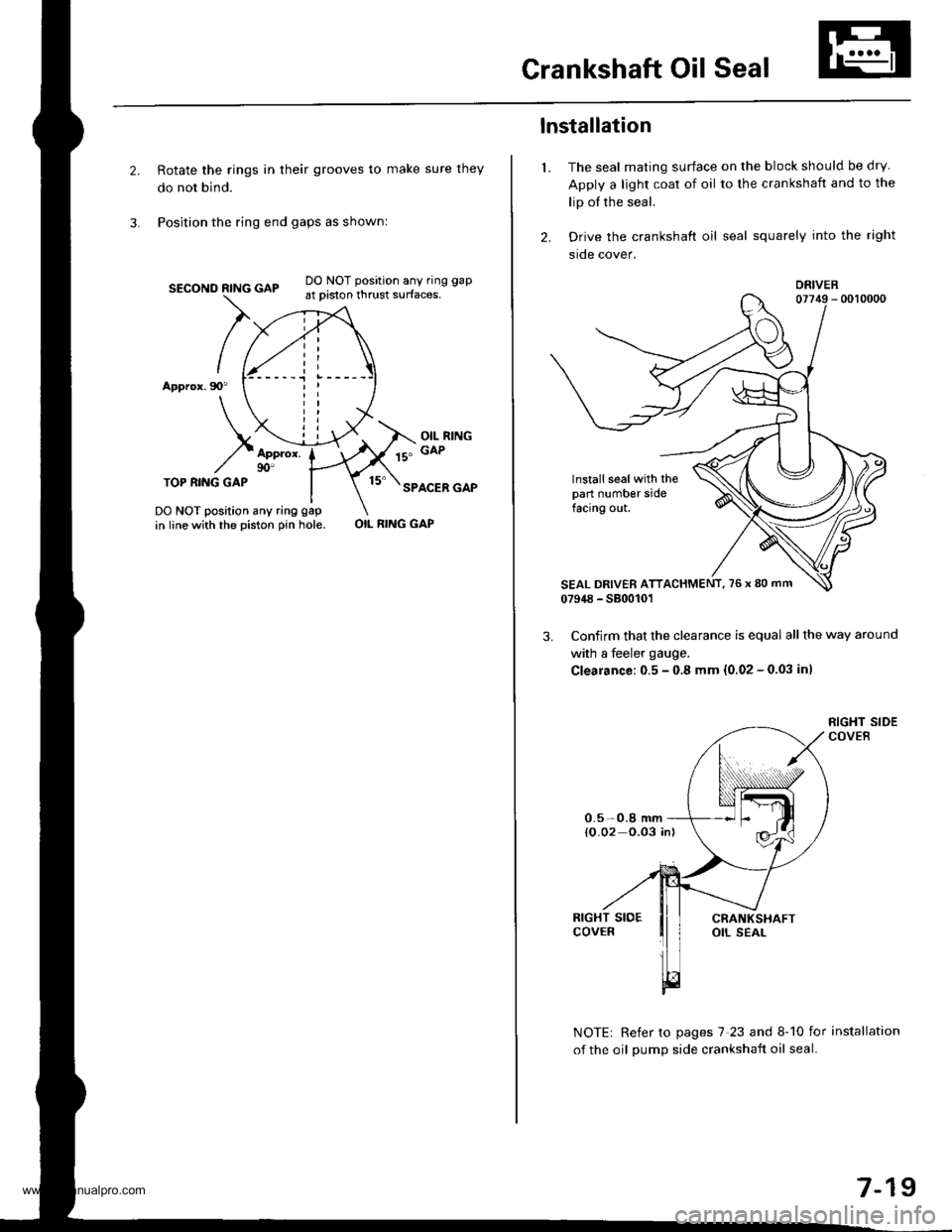
Crankshaft Oil Seal
Rotate the rings in their grooves to make sure they
do not bind.
Position the ring end gaps as shownl
SECOND RING GAP
Appror.90"
DO NOT position any ring gap
at piston thrust surfaces,
OIL RINGGAPAppror.90'TOP RI.IIG GAPSPACER GAP
DO NOT position any ring gap
in line with the piston pin hole.OIL RING GAP
1.
lnstallation
The seal mating surface on the block should be dry
Apply a light coat of oil to the crankshaft and to the
lip of the seal.
Drive the crankshaft oil seal squarely into the right
sroe cover.
DRIVER
lnstall seal with thepart number sidefacing out.
Confirm that the clearance is equal all the way around
with a feeler gauge.
Clearance:0.5 - 0.8 mm {0.02 - 0.03 inl
NOTE| Refer to pages 7 23 and 8-10 for installation
of the oil oumD side crankshait oil seal.
0.5-0.8 mm{O.02 0.03 in)
7-19
www.emanualpro.com
Page 172 of 1395
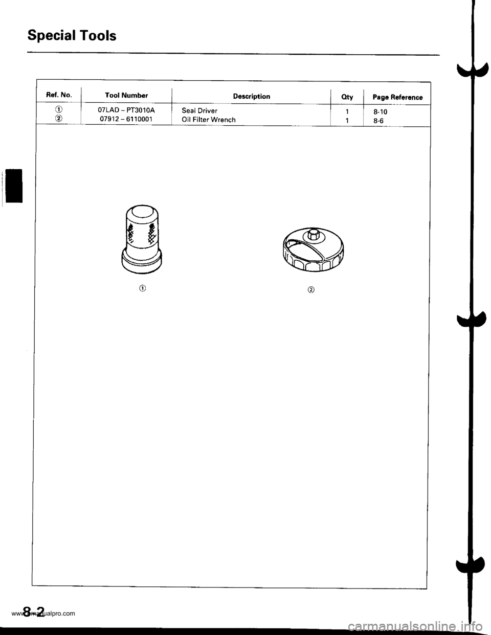
Special Tools
Ret. No. I Tool NumberIDescriptionOty i Pagc Roforance
oOTLAD _ PT3O1OA
079'12 - 6110001
Seal Driver
Oil Filter Wrench
1
1
8-10
8-6
8-2
www.emanualpro.com
Page 180 of 1395
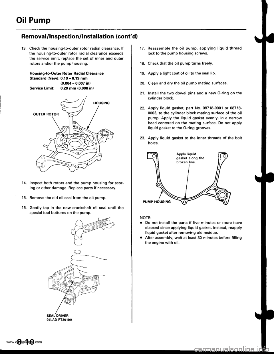
Oil Pump
13.
Removal/lnspection/lnstallation (cont'd)
Check the housing-to-outer rotor radial clearance. lf
the housing-to-outer rotor radial clearance exceeds
the service limit, reDlace the set of inner and outer
rotors and/or the pump housing,
Housing-to-Outer Rotor Radial Clearance
Standard lNewl: 0.10 - 0.19 mm
{0.004 - 0.007 in}
Service Limit: 0.20 mm {0.008 inl
Inspect both rotors and the pump housing for scor-
ing or other damage. Replace pans if necessary.
Remove the old oil seal from the oil pump.
Gently tap in the new crankshaft oil seal until the
special tool bottoms on the pump.
14.
15.
16.
8-10
17.Reassemble the oil pump, applying liquid thread
lock to the pump housing screws.
Check that the oil pump turns freely.
Apply a light coat ot oil to the seal lip.
Clean and dry the oil pump mating surfaces.
Install the two dowel pins and a new O-ring on the
cylinder block.
Apply liquid gasket, part No. 08718-0001 or 08718-
0003, to the cylinder block mating surface of the oil
pump. Apply the liquid gasket evenly, in a narrow
bead centered on the mating surface. Do not apply
liquid gasket to the O-ring grooves.
Apply liquid gasket to the inner threads of the bolt
noles.
18.
19.
20.
21.
Apply liquidgasket along thebroken line.
PUMP HOUSING
NOTE:
. Do not install the pans if five minutes or more have
elapsed since applying liquid gasket. Instead, reapply
liquid gasket after removing old residue.
. After assembly, wait at least 30 minutes betore filling
the engine with oil.
www.emanualpro.com
Page 181 of 1395
24.Apply grease to the lip of the oil pump seal.
Install the oil pump onto the crankshaft. When the
pump is in place, clean any excess grease off the
crankshaft and check that the oil seal lip is not dis-
torted.
lnstall the oil screen.
Install the oil pan {see page 7-22).2't .
8 x 1.25 mm24 N.m 12.4 kgf.m,'17 tbf.ft)
O-RINGApply engine oilReplace.
6x1.0mm9.8 N.m {1.0 kgf.m,1 .2lbfitl
DOWELPIN
6x1.0mm9.8 N.m (1.0 kgf.m.7.2 tbtftl
OIL PUMP
6x1.0mm9.8Nm(1.0kgf.m,7.2 tbt ft)
OIL SCBEEN
8-11
www.emanualpro.com
Page 899 of 1395
Suspension
Special Tools ............. 18-2
Component Locations
lndex ................ ...... 18-3
Wheel Alignment
Service lnformation ......................,.. 18-4
Camber .................. 18-4
Caster ............... ...... 18-5
Front Toe Inspection/
Adiustment ........ 18-5
Rear Toe Inspection/
Adiustment ........ 18-6
Turning Angle Inspection/
Adiustment ........ 18-6
Wheel/Hub Inspection
Bearing End Play .......................,...... 18-7
Wheel Runout ....... 18-7
Front Suspension
Suspension Arms Replacement ..... 18-8
Knuckle/Hub Replacement ............. 18-9
Lower Ball Joint Replacement ....... 18-15
Ball Joint Boot Replacement .......... 18-16
Front Damper
Removal ................. 18-16
Disassembly/lnspection .................. 18-1 7
Reassembly ........... 18-18
lnstallation ............. 18-18
Rear Suspension
Suspension Arms Replacement ..... 18-19
Hub Bearing Unit Replacement ...... 18-20
Upper Arm Bushing
Replacement ..... 18-23
Rear Damper
Removal ................. 18-23
Disassembly/1nspection .................. 18-24
Reassembly ........... 18-25
lnstallation ............. 18-25
www.emanualpro.com