1998 HONDA CR-V Vacuum system
[x] Cancel search: Vacuum systemPage 17 of 1395
![HONDA CR-V 1998 RD1-RD3 / 1.G Workshop Manual
Under-hood Emissions Control Label
Emission Group ldentification
(1997 modell
Example:
VACUUM HOSE ROUTING DIAGRAM
LOADED IM TEST]NG OF PERMANENT fOUB WHEEL OSVE OR TRACT ON CONTROLEOLJIPPEDVEHTCLES HONDA CR-V 1998 RD1-RD3 / 1.G Workshop Manual
Under-hood Emissions Control Label
Emission Group ldentification
(1997 modell
Example:
VACUUM HOSE ROUTING DIAGRAM
LOADED IM TEST]NG OF PERMANENT fOUB WHEEL OSVE OR TRACT ON CONTROLEOLJIPPEDVEHTCLES](/manual-img/13/5778/w960_5778-16.png)
Under-hood Emissions Control Label
Emission Group ldentification
(1997 modell
Example:
VACUUM HOSE ROUTING DIAGRAM
LOADED IM TEST]NG OF PERMANENT fOUB WHEEL OSVE OR TRACT ON CONTROL'EOLJIPPEDVEHTCLES MUST BE CONDUCTED ON A IOUR WHEEL DR VE SPEEO SYNCHRON ZED
ANON LOADEDTESTPBO(EOUBEMUSIBEPERFORMEO
50ST (50 Statesl:
THIS VEHICLE CONFOBMS TO U.S. EPA AND STATE OF
CALIFORNIA REGULATIONS APPLICABLE TO 1997
MODEL YEAR NEW LIGHT DUTY TRUCKS.
49ST {49 Statos/Federall:
THIS VEHICLE CONFORMS TO U.S. EPA REGULATIONS
APPLICABLE TO 1997 IVIODEL YEAR NEW LIGHT DUTY
TRUCKS.
CAL (Calitornial:
THIS VEHICLE CONFORMS TO U.S. EPA AND STATE OF
CALIFORN IA REGULATIONS APPLICABLE TO '1997
MODEL YEAR NEW TLEV LIGHT DUTY TRUCKS
PROVIDED THAT THIS VEHICLE IS ONLY INTRODUCED
INTO COMMERCE FOR SALE IN THE STATE OF
CALIFORNIA.
Ii/PORTANT VEHICLE INFORIMATIONENGINE FAMILY VHN2 OIJCrcKDISPIACEMENT'2 OLITEREVAPORAT VE f AM]LY VNNl0778YMBP
CATALYSTREfERTOSEBVICEMANUALfORAODITIONAL NFORMATON.TUNT I-]P CONDITIONSENGINE AT NORI\,!AL OPERATNG TEMPERATURE,ALLACCESSOR ES TL]RNED OFF COOLING FAN OIFTRANSM1SSION NNEUTRALNO OTHEB ADJUSTMENIS NEEDED
ap' | \6( Zror '. ND \. 61F L r
TNIS VENICLE CONFORMS TO U.S EPA REGUI.ATIONSAPPI CASLE TO I99] MODET YEAR N€W L GNI DUTY TRACKS
@
Engine Family: vHN2.o l JGKE
Engine and Evaporative Families
T_fT
Model Year I Iv:1s97 | LManufaqturer iHN: Honda I
Displacement
Class
1: Light Duty Vehicle
Fuol Systom ,nd Numb€r of valves
J: Electronic Sequential Multiport
Injection (three or more valves per
cylinder)
Fuel Type
G: Gasoline
Standard
F: 49 or 50 States Tier 1
K: 49 or 50 States Tier 1
1: California Tier 1
2: California TLEV
3: California LEV
4: California ULEV
"r0", "*,
T|
V: 1997
Manufacturer
HN: Honda
Catalyst
E, F, G, H: Three Way Catalyst
OBD
K - T: OBD Equipped
Evaporative Family:
Storago System
1: Canister
Canistor Working Capacity (gramsl
Canister Conf igulation
A: Plastic Housing (Closed Bottom)
B: Plastic Housing (OPen Bottom)
Fusl System
Y: Fuel Injection
FuelTank
M: Metal
Standard
A: Current Evap
B: Enhanced Evap
Wild C.rd
VHNlOTTBYMBP
1-1 5
www.emanualpro.com
Page 91 of 1395
n-
n-
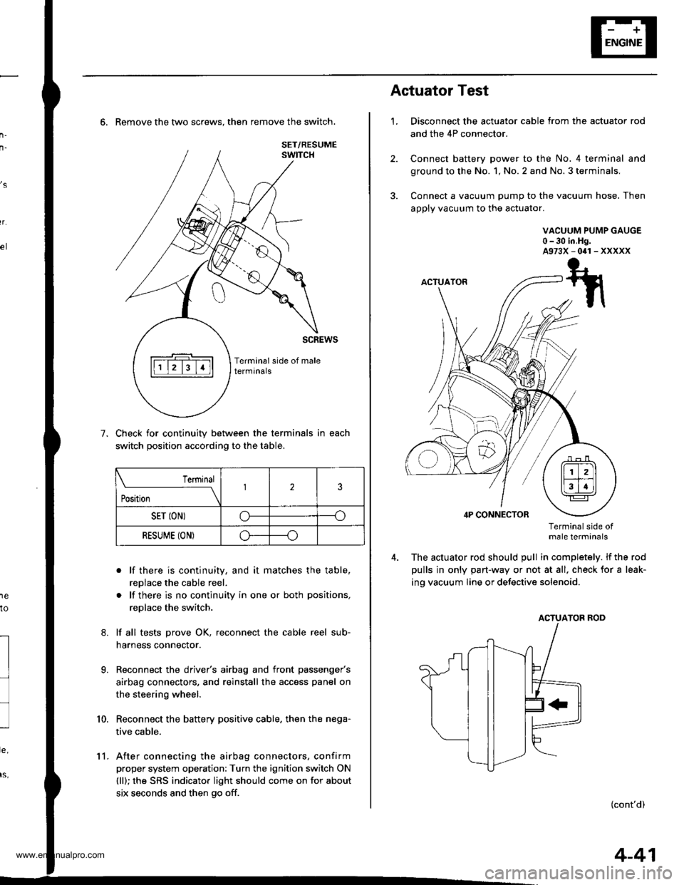
6. Remove the two screws. then remove the switch.
Check for continuity between the terminals in each
switch position according to the table.
. lf there is continuity, and it matches the table,
replace the cable reel.
. lf there is no continuity in one or both positions,
replace the switch.
lf all tests prove OK, reconnect the cable reel sub-
harness connector.
Reconnect the driver's airbag and front passenger's
airbag connectors, and reinstall the access panel on
the steering wheel.
Reconnect the battery positive cable. then the nega-
tive cable.
After connecting the airbag connectors, confirm
proper system operation: Turn the ignition switch ON
(ll); the SRS indicator light should come on for about
six seconds and then go off.
,s
r.
1e
to
7.
l
9.
10.
SET/RESUME
Terminal
t*,r*
-__\l23
SET ION)o----o
RESUME (ON)o----o
11.
4-41
1.
Actuator Test
Disconnect the actuator cable trom the actuator rod
and the 4P connector.
Connect battery power to the No. 4 terminal and
ground to the No. 1, No. 2 and No. 3 terminals,
Connect a vacuum pump to the vacuum hose. Then
apply vacuum to the actuator.
VACUUM PUMP GAUGE0-30 in.Hg.A973X-041-XXXXX
Terminalside otmale terminals
The actuator rod should pull in completely. lf the rod
pulls in only part-way or not at all, check for a leak-
ing vacuum Iine or defective solenoid.
ACTUATOB ROD
(cont'd)
www.emanualpro.com
Page 204 of 1395

Fuel and Emissions
Special Tools ...................... 11-2
Component Locations
lndex ...................... ....,.... 11-3
Svstem Description
Vacuum Connections ...........,....,.,................. 1 1-9
Electrical Connections ................................... 1 1-15
System Connectors .,.,,.,............................,.,. 1 1-36
Troubleshooting
Troubleshooting Procedures,.,..................... 11-60
Engine Control Module/Powertrain ConttolModule Terminal Arrangement .............., 11-67
Diagnostic Trouble Code Chart .................... 1 t-75
How to Read Flowcharts .......,.....,.,............... I 1-79
PGM-Fl System
System Description .................,.,.,,,............... 1 1-80
Troubleshooting Flowcharts
Engine Control Module/PowertrainControl Module ........11-52
Manifold Absolute Pressure Sensor ............. 11-90
Intake Air Temperature Sensor .................... 1 1-95
Engine Coolant Temperature Sensor .,..,.,.... 1 1-99
Throttle Position Sensor ...........,.....,.,.,..,...... I 1'103
Primary Heated Orygen Sensor (Sensor 1) ... 11-110
Secondary Heated Oxygen Sensor{Sensor 2l .................. 1 1-117
Heated Oxygen Sensor Heater ..................... 11-121
Fuef Supply System ......11-124
Random Misfire ,....,.,..... 11-126
Mistire Detected in One Cylinder .....-........... 11-128
Knock Sensor ................ 11-130
CKP/TDC/CYP Sensor .................................... 1 1-131
Vehicle Speed Sensor ...............................,.... 1 1-135
Barometric Pressure Sensor .....,...,...,.,,........ 1 1-137
Electrical Load Detector ...,.,.......................... 1 1-138
CKF Sensor ................,.,, '11-112
ECM/PCM lnternaf Circuit ............................. 11'117
HO2S Replacement .,.,.,. 11-148
ldle Control System
System Description ............ 11-149
Troubleshooting Flowcharts
ldle Control System ...... 11-150
fdle Air Control Valve ......................,............. 11-152
Air Conditioning Signal ................................. I 1-155
Alternator FR Signal ...................................... 1 1-159
Starter Switch Si9na1 .................................... t l-161
Power Steering Pressure Switch Signal ...... 11-162
Brake Switch Si9na1 ...................................... 11-166
Fast ldle Thermo Valve .,.,.............................,.,.,. 11-168
ldle speed setting .............. 11-169
Fuel Supply System
Fuel Lines ............................ 11-171
Fuef Tube/Ouick-Conneci Fittings ..................... 11 -175
System Description ............ 11-178
Fuel Pressurg ...................... 11-178
Fuel Iniectors ................,..... 11-179
Fuel Pressure Re9u1ator .............................,.,...., f 1-181
Fuef Fifter ....,.,.,.,,,,.,............11-142
Fuel Pump ........................... 11-183
Fuel Gauge .......................... 11-184
Fuel Gauge Sending Unit ................................... I 1-185
Low Fuel Indicator System ...........,.,..,............... 1 1-185
PGM-FI Main Relay ............. 11-187
Fue|Tank................ ............. 11-191
Intake Air System
System Description ............ 11-193
Air Cleanel ,.,.,..................... 11-194
Throttle Cable ..................... 11-194
Throttle Body........ .............. 11-196
Emission Control System
System D$cription ...,....,.,. 11-199
Tailpipe Emission ............... 11-199
Three Way Catalytic Converter ..................,.,...,, 11-199
Positive Crankcase Ventilation System .,.,,,,.,.., 11-2O1
Evaporative Emission Controls .........,.,.,............ 11-203
www.emanualpro.com
Page 213 of 1395
System Description
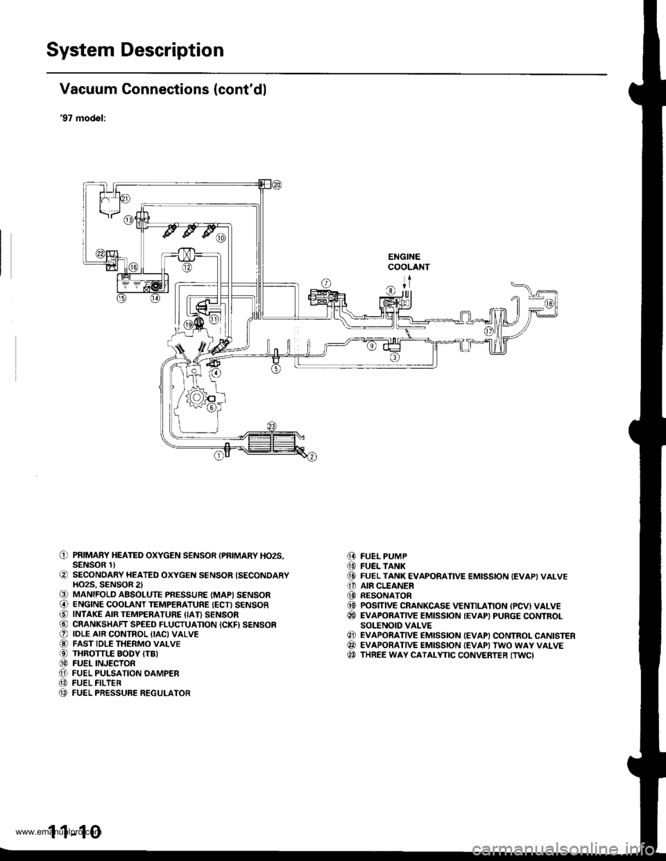
Vacuum Connections (cont'dl
'97 model:
ENGINECOOLANT
ITr|ll
O PRIMARY HEATED oxYGEN sENsoR {PRIMARY Ho2s,SENSOR lt
O SECONDARY HEATED oxYGEN sENsoR {SECoNDARYHO2S. SENSOR 2l€) MANIFOLD ABSOLUTE PRESSURE (MAPI SENSOR@ ENGINE cooLANT TEMPERATURE {EcT} sENsoRO INTAKE AIR TEMPERATURE (IAI} sENsoR@ CRANKSHAFT SPEED FLUCTUATION ICKFI SENSORO |DLE ArR coNTRoL {tAc)vALvE@ FAST IDLE THERMo vALvEO THRoTTLE EoDY ITB)@ FUEL INJEcTonO FUEL PULSATIoN oAMPER@ FUEL FILTEn(} FUEL PRESSURE REGULATOR
FUEL PUMPFUEL TANKFUEL TANK EVAPORATIVE EMISSION (EVAPIVALVEAIR CLEANERRESONATORPOSITIVE CRANKCASE VENTILATION {PCVI VALVEEVAPORATIVE EMISSION {EVAP} PURGE CONTROLSOI.'ENOID VALVEEVAPORATIVE EMISSION {EVAP) CONTROL CANISTEREVAPORATIVE EMISSION {EVAPI TWO WAY VALVETHREE WAY CATALYTIC CONVERTER (TWC)
@(D(D
o@(}
@
@@@
1 1-10
www.emanualpro.com
Page 215 of 1395
System Description
I
I
I
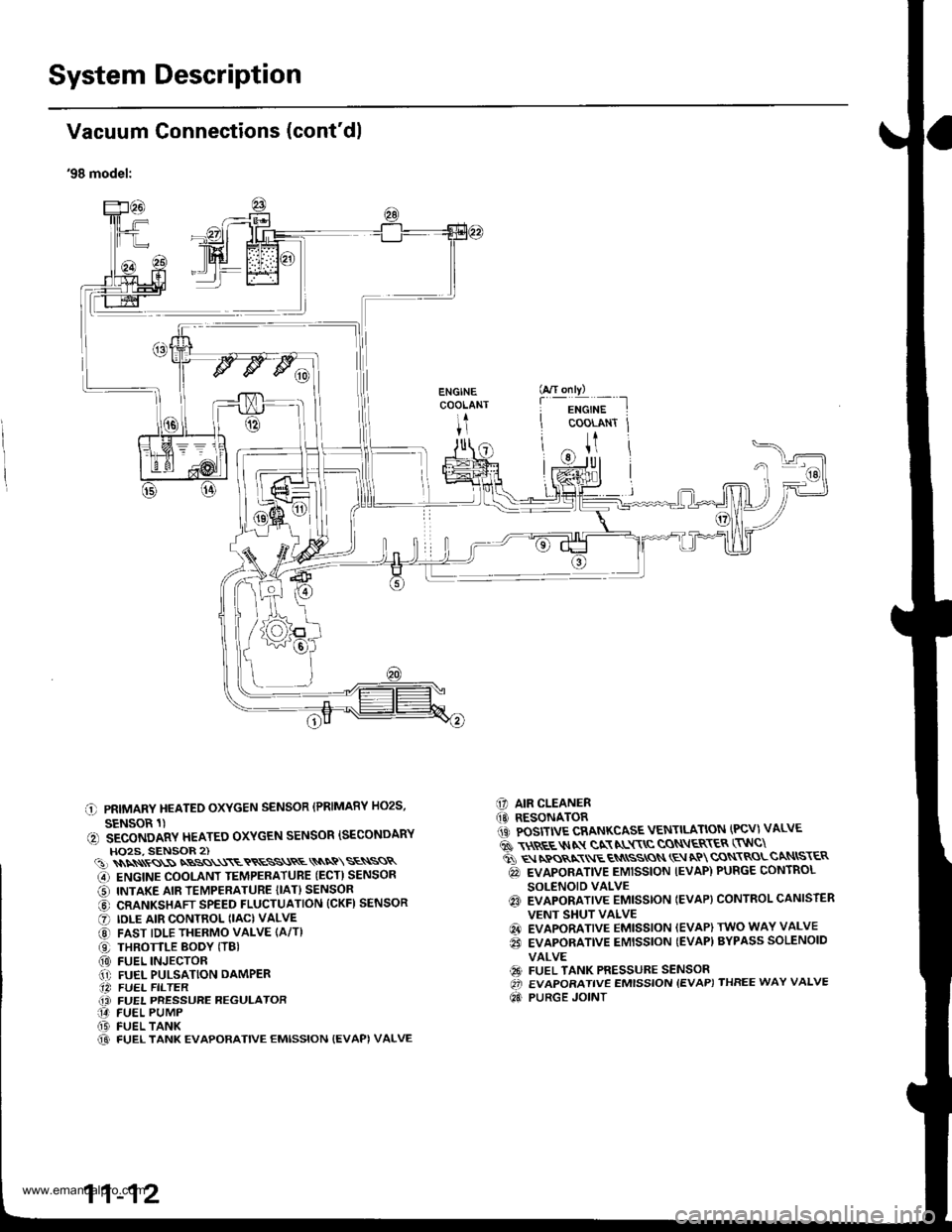
Vacuum Connections (cont'dl
'98 model:
C PRIMARY HEATEO OXYGEN SENSOR (PRIMARY HO2S,
SENSOR 1)(, SECONDARY HEATEO OXYGEN SENSOR ISECONDARYHO2S, SENSOR 2)(!)\\\\ss\SNBSS\\\ETRESS\RE\\NQ\SE\SSR
G) ENGINE COOLANT TEMPERATUBE (ECT) SENSOR
O INTAKE AIR TEMPERATURE {IAT} SENSOR
@ CRANKSHAFT SPEED FLUCTUATION (CKFI SENSOR
O IDLE AIR CONTROL (IAC) VALVE
@ FAST IDLE THERMO VALVE (A/T)
O THROTTLE BODY (TBI(0) FUEL INJECTOR.1' FUEL PULSATION DAMPER.14 FUEL FILTER(i FUEL PRESSURE REGULATOR14 FUEL PUMP(D FUEL TANK@ FUEL TANK EVAPORATIVE EMISSION {EVAPI VALVE
C] AIR CLEANER(O RESONATOR1iC POSITIVE CRANKCASE VENTILATION (PCV) VALVE
6 \$REE$IN gN NL$\C CON\ER\ER (TNC\
ti q rpos,xr E qN
ssros \E aP cqN\RoLcaNtsr€R
@ EVAPORATIVE EMISSION IEVAP) PURGE CONTROL
SOLENOID VALVEq3 EVAPORATIVE EMISSTON IEVAP} CONTROL CANISTER
VENT SHUT VALVE
@ EVAPORATIVE EMISSION (EVAP) TWO WAY VALVE
€i EVAPORATIVE EMISSION {EVAP) BYPASS SOLENOID
VALVE
€9 FUEL TANK PRESSURE SENSOROi EVAPORATIVE EMISSION {EVAP) THREE WAY VALVE
Qd PURGE JOINT
G/T only)
f
-i*'";-t
COOLANT Jt
U
11-12
www.emanualpro.com
Page 217 of 1395
System Description
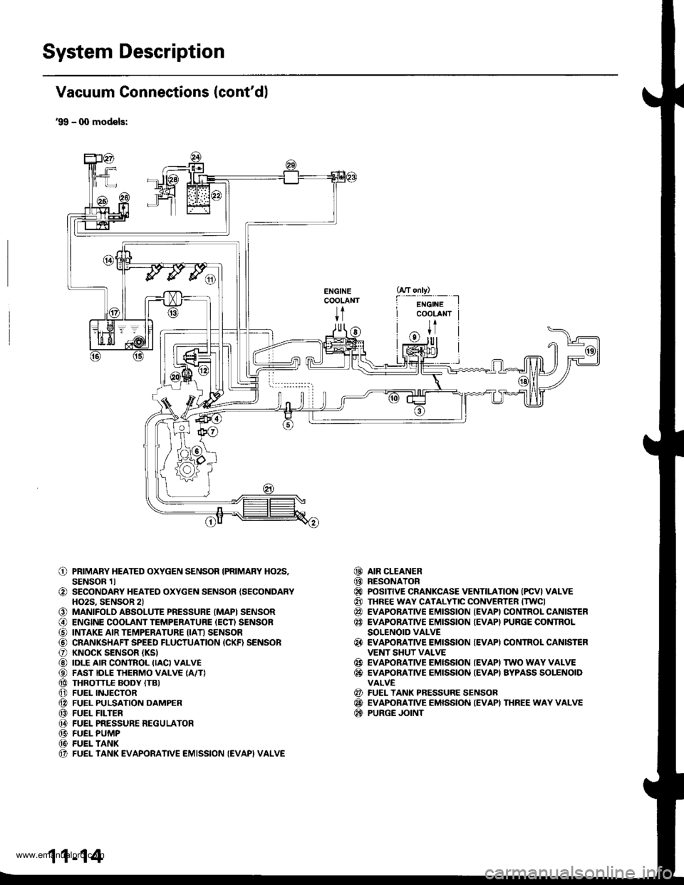
Vacuum Connections (cont'dl
'99 - q) models:
ENGINECOOLANT
t
o
o
o@
o@@@@@@@@@(t
PRIMARY HEATED OXYGEN SENSOR IPRIMARY HO2S,SENSOR 1lSECONDARY HEATED OXYGEN SENSOR {SECONDARYHO2S. SENSOR 2lMANIFOLD ABSOLUTE PRESSURE (MAPI SENSORENGINE COOLANT TEMPERATURE IECN SENSORINTAKE AIR TEMPERATURE IIATI SENSORCRANKSHAFT SPEED FLUCTUATION {CKF) SENSORKNOCK SENSOR (KS}
IDLE AIR CONTROL IIACI VALVEFAST IDLE THERMO VALVE {A/T}THROTTLE BODY (TB}
FUEL INJECTORFUEL PULSATION DAMPERFUEL FILTERFUEL PRESSURE REGULATORFUEL PUMPFUEL TANKFUEL TANK EVAPORATIVE EMISSION (EVAPI VALVE
AIR CLEANERRESONATORPOSITIVE CRANKCASE VENTILATION (PCV} VALVETHREE WAY CATALYTIC CONVERTER ITWCIEVAPORATIVE EMISSION {EVAPI CONTROL CANISTEREVAPORATIVE EMISSION IEVAPI PURGE CONTROLSOLENOID VALVEEVAPORATIVE EMISSION {EVAPI CONTROL CANISTEFVENT SHUT VALVEEVAPORATIVE EMISSION IEVAPI TWO WAY VALVEEVAPONANVE EMISSION {EVAPI AYPASS SOLENOIDVALVEFUEL TANK PRESSURE SENSOBEVAPORATIVE EMISSION IEVAPI THREE WAY VALVEPURGE JOINT
@@@@@@
@
@@
@@@
11-14
www.emanualpro.com
Page 280 of 1395
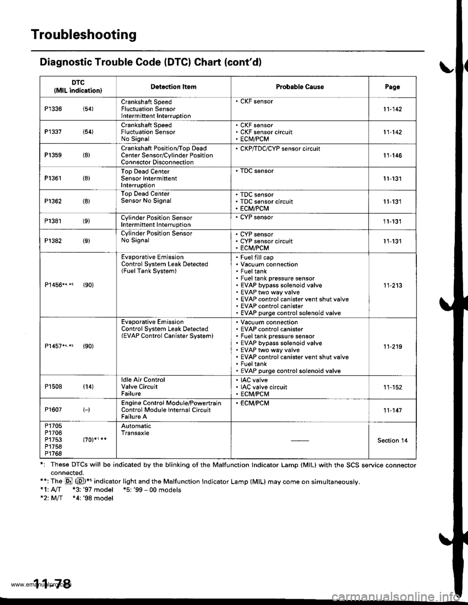
Troubleshooting
Diagnostic Trouble Code (DTCI Ghart (cont'd)
r: These DTCS will be indicated by the blinking oJ the Malfunction Indicator Lamp (MlL) with the SCS service connectorconnected.**: The Di (E)*5 indicator light and the Malfunction tndicator Lamp (MlL) may come on simultaneously.*1: A[f *3;'97 model *5: '99 - 00 models*21M/f *4: '98 model
11-78
DTC
{MlL indication}Detection ltemProbable CausePagc
P1336 154)Crankshaft SpeedFluctuation SensorIntermittent Interruption
. CKF sensor
11-142
P1337 i54)Crankshaft SpeedFluctuation SensorNo Signal
CKF sensorCKF sensor circuitECM,FCM11-142
P1359 (8)Crankshaft Position/Too DeadCenter Sensorrcylinder PositionConnector Disconnection
' CKP/TDC/CYP sensor circuit11-146
P1361 (8)Top Dead CenterSensor IntermittentInterruption11-131
P1362 (8)Top Dead CenterSensor No SignalTDC sensorTDC sensor circuitECM/PCM11-131
P1381 (9)Cylinder Position SensorIntermittent Interruption
. CYP sensor11-131
P1382 (9)Cylinder Position SensorNo SignalCYP sensorCYP sensor circuitECM/PCM11-131
P1456n.* {90}
Evaporative EmissionControl System Leak Detected(FuelTank System)
Fuelfill capVacuum connectionFueltankFuel tank prossure sensorEVAP bypass solenoid valveEVAP two way valveEVAP control canister vent shut valveEVAP control canisterEVAP purge controlsolenoid valve
11-213
Pr457n.s {90)
Evaporative EmissionControl System Leak Detected(EVAP Control Canister Svstem)
Vacuum connectionEVAP control canisterFuel tank pressure sensorEVAP bypass solenoid valveEVAP two way valveEVAP control canister vent shut valveFueltankEVAP purge controlsolenoid valve
11-219
P1508 (14)ldle Air ControlValve CircuitFailure
IAC valveIAC valve circuitECM/PCM11-152
Pr607(-)Engine Control Module,PowertrainControl Module Internal CircuitFailure A
. ECM,FCM11-147
P1705P1706P1753P1758P1768
AutomaticTransaxle
Section '14
www.emanualpro.com
Page 283 of 1395

Fuel Cut-off Control
. During deceleration with the throttle valve closed, current to the fuel injectors iscutoffto improvefuel economyat
speeds over 970 rpm ('97 - 98 models), 920 rpm ('99 - 00 modelsl.
. Fuel cut-off action also takes place when engine speed exceeds 6,500 rpm ('97 - 98 models), 6900 rpm ('99 - 00
models), regardless of the position of the throttle valve, to protect the engine from over-rewing.
With Ay'T model. the PCM cuts the fuel at engine speeds over 5,000 rpm when the vehicle is not moving.*'�
4,./C Comoressor Clutch Relav
When the ECM/PCM receives a demand for cooling from the air conditioning system, it delays the compressor from
being energized, and enriches the mixture to assure a smooth transition to the Ay'C mode.
Evaporative Emission (EVAP) Purge Control Solenoid Valve
When the engine coolant temperature is above 154"F (68'C), the ECM/PCM controls the EVAP purge control solenoid
valve which controls vacuum to the EVAP purge control canister,
Alternator Control
The system controls the voltage generated at the alternator in accordance with the electrical load and driving mode.
which reduces the engine load to improve the fuel economy.
PCM Fail-saf e/Back-up Functions
1. Fail-safe Function
When an abnormality occurs in a signal from a sensor, the ECM/PCM ignores that signal and assumes a pre-pre
grammed value for that sensor that allows the engine to continue to run.
2. Back-up Function
When an abnormality occurs in the ECM/PCM itself, the fuel injectors are controlled by a back-up circuit independent
of the system in order to permit minimal driving.
3. Self-diagnosis Function IMalfunction Indicator Lamp (MlL)l
When an abnormality occurs in a signal from a sensor, the ECM/PCM supplies ground for the MIL and stores the DTC
in erasable memory. When the ignition is initially turned on {ll), the ECM/PCM supplies ground for the MIL for two
seconds to check the MIL bulb condition.
4. Two Trio Detection Method
To prevent false indications, the Two Trip Detection Method is used for the HO2S*1, fuel metering-related. idle control
system, ECT sensor and EVAP control system self-diagnostic functions. When an abnormality occurs, the ECM/PCM
stores it in its memory. When the same abnormality recurs after the ignition switch is turned OFF and ON (ll) again,
the ECM/PCM informs the driver by lighting the MlL. However, to ease troubleshooting, this function is cancelled
when you jump the service check connector, The MIL will then blink immediately when an abnormality occurs.
5. Two (or Three) Driving Cycle Detection Method {'97 model)
A "Driving Cycle" consists of starting the engine, beginning closed loop operation, and stopping the engine. lf misfir-
ing that increases emissions or EVAP control system malfunction is detected during two consecutive driving cycles.
or TWC deterioration is detected during three consecutive driving cycles, the ECM/PCM turns the MIL on. However, to
ease troubleshooting, this function is cancelled when you jump the service check connector. The MIL will then blink
immediately when an abnormality occurs.
*1: '97 - 98 models*2: '99 - 00 models
5.
www.emanualpro.com