Page 974 of 1395

(From page 19-50)
Chcck for .n opsn in the PCOMcircuit:1. Turn the ignition switch OFF.2. Reconnect the ABS controlunit 22P connector.3. Connect the SCS service con-nector.4. Turn the ignition switch ON {ll).5. Measure the voltage betweenthe pump motor relay con-nector PCOM terminal andbody ground.
Repair opon in the wire betwoenthe under-hood ABS fuse/relaybox and tho ABS conlrol unh.ls there approx.3 V?
Check for an open in tho PMR cir-cuh:Measure the voltage between theABS control unit 22P connectorterminal No. 19 and body ground.
Ropair open in tho wir6 botwagntho undcr-hood ABS fuse/rolaybox .nd the ABS control unit.ls there approx. 3 V?
Ch.ck tor an opon in the MCKci.cuit:1. Turn the ignition switch OFF.2. Disconnect the SCS serviceconnector.3. Turn the ignition switch ON (ll).
4. Measure the voltage betweenthe ABS control unit 22P connector terminal No. 17 andbody ground while connect-ing the pump motor relayconnector +B and MOTOR ter-minal with a jumper wire tormoment,
Repair open in the wiro bdtweenthe under-hood ABS fus6/telaybox .nd the ABS control unit.ls there battery voltage?
Chock for loose ABS control unitconnectoas, It necsssary, substi-tule a known-good ABS controlunit and aocheck.
tr) l--l
r"r
ABS CONTROL UNIT 22P CO NECTOR
Wire side of female terminals
1t011
MCK IBRN,/YEL}
www.emanualpro.com
Page 975 of 1395
![HONDA CR-V 1998 RD1-RD3 / 1.G Workshop Manual
Troubleshooting
DTG 54: Main Relay
IWHT/GRNI
AAS CONTROL UNIT 26P CONNECTON
Wire side of female terminals
ABS COf{TROL UN]T 22P CONNECTOR
PCOMIGRN/WHTIscoM{BLK/WHTI
Wire side of female terminals
- Wi HONDA CR-V 1998 RD1-RD3 / 1.G Workshop Manual
Troubleshooting
DTG 54: Main Relay
IWHT/GRNI
AAS CONTROL UNIT 26P CONNECTON
Wire side of female terminals
ABS COf{TROL UN]T 22P CONNECTOR
PCOMIGRN/WHTIscoM{BLK/WHTI
Wire side of female terminals
- Wi](/manual-img/13/5778/w960_5778-974.png)
Troubleshooting
DTG 54: Main Relay
IWHT/GRNI
AAS CONTROL UNIT 26P CONNECTON
Wire side of female terminals
ABS COf{TROL UN]T 22P CONNECTOR
PCOMIGRN/WHTIscoM{BLK/WHTI
Wire side of female terminals
- With the ignition switch ON(lll, the ABS indicator doesnot go off.- With the SCS service connec-tor connected {see page 19-381,DTC 54 is indicatod.
Check the ABS +B 120 A) fuse inthe under-hood ABS luse/relaybox, and reinstall the fuse if it isoK.
FeDlace the tu3e and recheck.
Ch€ck tor an open in the 81, 82circuit:Measure the voltage betweenbody ground and the ABS controlunit 26P connector terminal No. 14and No. 15 individually.
Repair open in the wiro bstweonth6 ABS conirol unit and theunder-hood ABS fuse/rolay box,
ls there battery voltage?
Check for a short to body groundin the PMR circuit:L Turn the ignition switch OFF.2. Remove the pump motor relay.3. Disconnect the ABS controlunit 22P connector.4. Check lor continuity betweenterminal No. 19 and bodygrouno.
Repair short to body ground inthe wire betweon the under-hood ABS lGe/r.lay box and theABS control unit.
Check for a short to body groundin the PCOM, SCOM cilcuit:1. Disconnect the ABS controlunit 26P connector.2. Check tor continuity betweenbody ground and the ABS con-trol unit 26P terminals No- 1and No.2 individually.
. R€pair short to body ground inth€ P1COM circuit wire betweenthe ABS control unit and theund6r-hood ABS tuse/r6layoox.. R6p.ir short to body ground inthe PCOM or SCOM circuit wirebetweon th6 ABS control unitand lhe mod!lator unit.. R.Dlece tho modulrtor unit.(Short circuit inside the unitl
ls there continuity?
(To page 19-53)
www.emanualpro.com
Page 976 of 1395
Check fo. a short to power in thaPCOM, SCOM circuhi1. Start the engine.2. Measure the voltage betweenbody ground and ABS controlunit 26P connector terminalsNo. I and No.2 individually.
'Repair short to powor in thsFCOM circuit wiro botwoon th€ABS control unit and the under-hood ABS tuse/r.lay box.. Repeir 3hort to power in thoPCOM or SCOM circuit wirebetwegn tho ABS control uniiand ths modulator unh,. R.placo tha modulatoi unit.(Shon to power in.ido th6 unitl
ls there 8 V or more?
Tu.n tho ignhion switch OFF andconnect thc SCS 3orvice connec-tor. Then turn thc ignition switchON (lll and measure tha voltagobotween the PCOM .nd SCOMtsrminal3 and body gJound. Itther6 is 0 V, .epleco tho ABS con-trol unit.
ABS CONTROL UNIT 26P CONNECTOR
PCOM
Wire side of temale terminals
NOTE: 8 V or more indicates a short to
(GRN/WHTI SCOM
www.emanualpro.com
Page 977 of 1395
Troubleshooting
DTC 61: lgnition Voltage
- Whh the .ngine running. theABS indicator b ON,- With the SCS servicc connaetor connoctod {sao prgo 1998},DTC 61 b indi)atod.
Problom vorification:1. Erase the DTC.2. Start the engine.
Does the ABS indicator come onand is DTC 61 indicated?Tho ryrtom i. OK rt thb timo.
Ch.ck the lG2 circuit:Measure the voltage betweon theABS control unit 26P connectorterminal No.3 and body ground.
ls there 18 V or above?
lf the volt gc b 0 V, ch6d( to. anoD€n in lhe lG2 circuh.I thole ir 12 - 17 V, subatilui. !known-good ABS control unit .ndr€d|eck.
Wire side of temale termioals
www.emanualpro.com
Page 978 of 1395
DTC 81: Central Processing Unit (CPUI
- with the ignition 3witch ON{ll}. the ABS indicator doesnot go off.- Whh the SCS sewice connec-tor connectod {see page 1938),DTC 81 b indicatod.
Problem vorific.tion:L Erase rne u t L.2. Test-drive the vehicle.
Does the ABS indicator come onand is DTC 81 indicated?R€place th. ABS control unit.
The system is OK at this time.
19-55
www.emanualpro.com
Page 1101 of 1395

Self-diagnosis Function
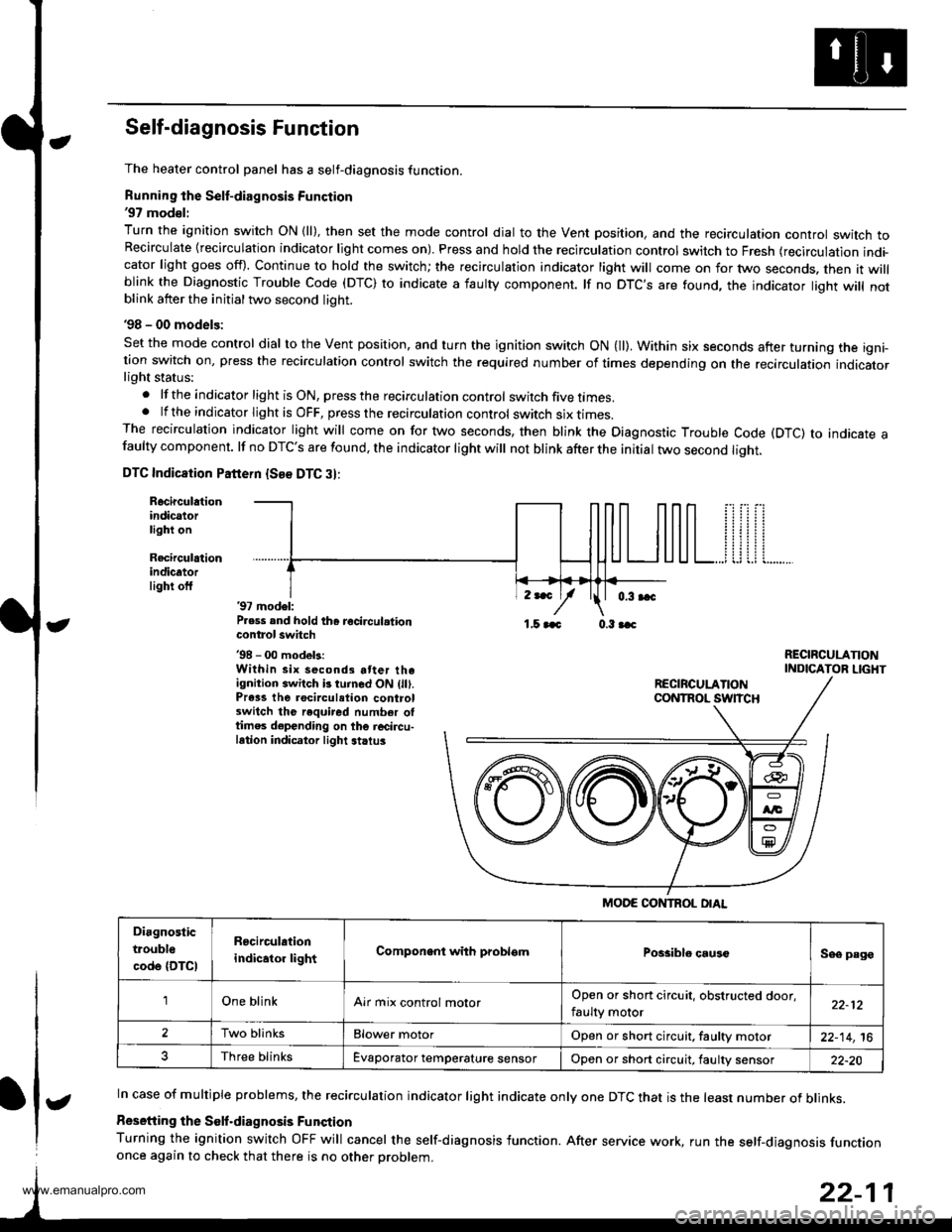
The heater control panel has a self-diagnosis function.
Running the Self-diagnosis Function'97 mod€l:
Turn the ignition switch ON {ll), then set the mode control dial to the Vent position, and the recirculation controt switch toRecirculate {recirculation indicator light comes on). Press and hold the recirculation control switch to Fresh (recirculation indi-cator light goes off). Continue to hold the switch; the recirculation indicator light will come on for two seconds. then it willblink the Diagnostic Trouble Code (DTC) to indicate a iaulty component. lf no DTC'S are found, the indicator liqht will notblink atter the initial two second light.
'98 - 00 models:
Set the mode control dial to the Vent position, and turn the ignition switch ON (ll). Within six seconds after turning the igni-tion switch on, press the recirculation control switch the required number of times depending on the recirculation indicatorlight status:
.lftheindicatorlightisON,presstherecirculationcontrol switch five times..lftheindicatorlightisOFF,presstherecirculationcontrol switch six I|mes.The recirculation indicator light will come on for two seconds, then blink the Diagnostic Trouble Code (DTC) to indicate afaulty component. lf no DTC'S are found, the indicator light will not blink after the initial two second liqht.
DTC Indicaiion Pattern {See DTC 3}:
Rocirculationindicatorlight on
Recirculrtionindicatorlighi off'97 model:P.ess and hold th6 recircul.tioncontrol switch'98 - 00 modek:Within six second3 atter theignition switch b turned ON (lll.Prass the rocirculation controlswitch the required number oltimes depending on the r6circu-lation indicator light striu3
,r*
/1.5 aaa 0.3 aac
RECIRCULANONINDICATOR LIGHT
In case of multiple problems, the recirculation indicator light indicate only one DTC that is the least number of blinks.
Resetiing the Solf.diagnosis Funqtion
Turning the ignition switch OFF will cancel the self-diagnosis function. After service work, run the self-diaqnosis functiononce again to check that there is no other Droblem.
MODE CONTROL OIAL
Diagnostic
trouble
code {DTCI
R6circulation
indicator lightComponent with problsmPossiblo causcSee page
'lOne blinkAir mix control molorOpen or short circuit, obstructed door,
faulty motor22-12
2Two blinksElower motorOpen or short circuit, faultv motor22-14,16
Three blinksEvaporator temperature sensorOpon or short circuit, faulty sensor22-20
t
www.emanualpro.com
Page 1311 of 1395
Special Tools
Ref. No. Tool NumberDescriptionOty I Page Reference
o"'
@-,/a\
@rA*,
07HAz - SG00500
07PM - 0010100
07sAz - TB40114
07TAZ - SZ50114
o7T AZ - OO1O20A
Deployment Tool
SCS Service Connector
SRS Inflator Simulator
SRS Simulator Lead C
Backprobe Adapter, l7 mm
1
1'1
I
2
24-91
24-21
24-50
24-50
24-43* 1: Included in SRS Tool Set 07MAZ - SM5000B*2: Use with the stacking patch cords from T/N 07SAZ - 0010004, Backprobe Set.
o@
/no
24-14
.-
www.emanualpro.com
Page 1323 of 1395

Troubleshooting
Self-diagnostic Procedures
The self-diagnostic function of the SRS system allows it to locate the causes of system problems and to store this informa-
tion in memory, For easier troubleshooting, this data can be retrieved via a data link circuit.
. When you turn the ignition switch ON (ll). the SRS indicator will come on. lf it goes off after six seconds, the system is
normal.
. lf there is 8n abnormality, the system locates and defines the problem. stores this information in memory, and turns
the SRS indicator light on. The data will remain in the memory even when the ignition switch is turned off or if the bat-
terv is disconnected.
. When you connect the SCS service connector to the service check connector (2P), and turn the ignition switch ON (ll),
the SRS indicator light will indicate the diagnostic trouble code (DTC) by the number of blinks.
. After reading and recording the DTC, proceed with the troubleshooting forthis code.
Precsutions
. Use only a digital multimeter to check the system. lf it's not a Honda multimeter. make sure its output is 10 mA (0.01 A)
or less when switched to the smallest value in the ohmmeter range. A tester with a higher output could damage the
airbag circuit or cause accidental airbag deployment and possible injury.
. Whenever the ignition switch isON (ll). or has been turned OFF for less than three minutes, be careful nottobumpthe
SRS unit; the airbags could accidentally deploy and cause damage or injuries.
. Before you remove the SRS main harness, disconnect the airbag and tensioner connectors (see page 24-23).
. Make sure the battery is sufficiently charged (see section 23). lf the battery is dead or low, measuring values won't be
correct.
. Do not touch a tester probe to the terminals in the SRS unit or harness connectors, and do not connect the terminals
with a jumper wire. Use only the backprobe set and the SCS service connector.
For backprobing spring-loaded lock type con nectors, .efet to page 24-22.
Reading the DTC
When the SRS indicator light is on, read the DTC using one of these methods;
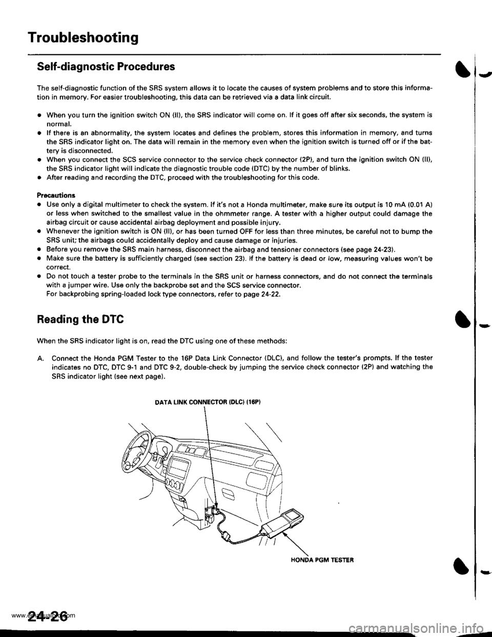
A. Connect the Honda PGM Tester to the 16P Data Link Connector {DLC), and follow the tester's prompts. lf the tester
indicates no DTC, DTC 9-1 and DTC 9-2, double-check by jumping the service check connector (2P) and watching the
SRS indicator light (see next page).
HONDA PGM TESTER
DATA LINK CONNECIOR {DLCI {16P)
24-26
,1
www.emanualpro.com