Page 393 of 1395

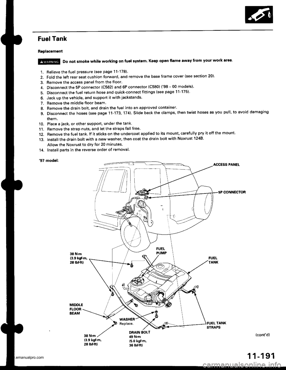
Fuel Tank
Replacement
1. Relieve the fuel pressure (see page 11-178).
2. Fold the left rear seat cushion forward, and remove the base frame cover {see section 20).
3. Remove the access panel from the floor.
4. Disconnect the 5P connector 1C562) and 6P connector (C580) ('98-00 models)'
5. Disconnect the fuel return hose and quick-connect fittings {see page 11-175}
6. Jack up the vehicle, and support it with jackstands.
7. Remove the middle floor beam.
8. Remove the drain bolt, and drain the fuel into an approved contaaner.
g. Disconnect the hoses (see page 11-173, 174). slide back the clamps. then twist hoses as you pull, to avoid damaging
them.
10. Place a jack, or other suppon, under the tank
11. Remove the strap nuts, and let the straps fall free
12. Remove the fuel tank. lf it sticks on the u ndercoat applied to its mount, carefu lly pry it off the mount,
'13. lnstallthe drain bolt with a new washer, then coat the drain bolt with Noxrust 1248'
Allow the Noxrust to dry for 20 minutes.
14. Install parts in the reverse order of removal.
'97 modol:AOCESS PANEL
CONNECTOR
@ Do not smoke while working on fuol systam Keep open flame away from your work area'
DRAIN EOLT49 N.m15.0 kgf'm,36 rbt frl
(cont'd)
1 1-191
www.emanualpro.com
Page 401 of 1395

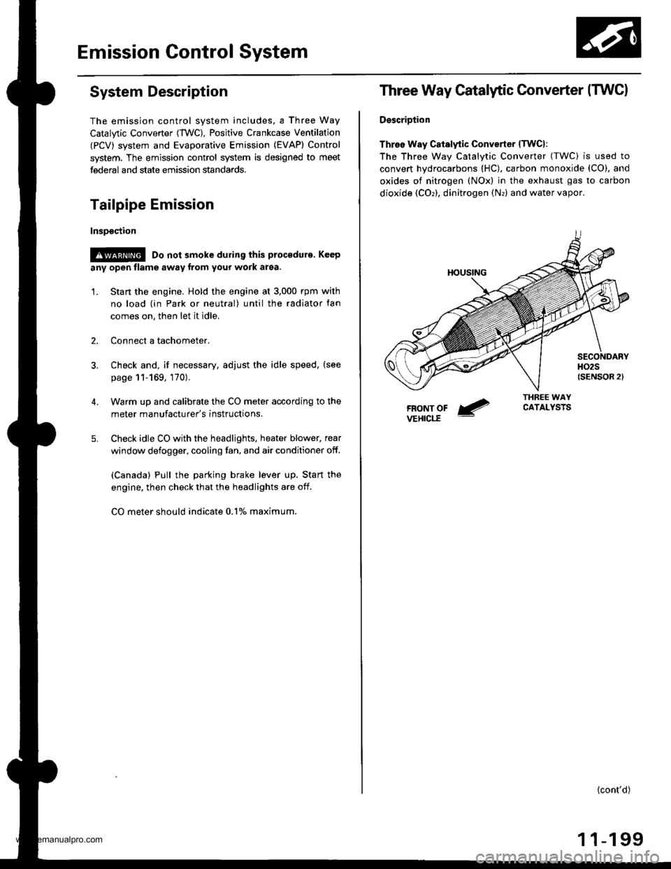
Emission Control System
System Description
The emission control system includes, a Three Way
Catalytic Converter {TWC), Positive Crankcase Ventilation
(PCV) svstem and Evaporative Emission (€VAP) Control
system. The emission control system is designed to meet
federal and state emission standards.
Tailpipe Emission
Inspsction
!@ Do not smoke during this procsdura. Keep
any open tlame away from your work area.
1. Start the engine. Hold the engine at 3,000 rpm with
no load (in Park or neutral) until the radiator fan
comes on, then let it idle,
Connect a tachometer.
Check and, if necessary, adjust the idle speed, (see
page 11-169, 170).
Warm up and calibrate the CO meter according to the
meter manufacturer's instructions.
Check idle CO with the headlights, heater blower, rear
window defogger, cooling fan, and air conditioner off.
(Canada) Pull the parking brake lever up. Start the
engine, then check that the headlights are off.
CO meter should indicate 0.1% maximum.
4.
Three Way Catalytic Converter (TWCI
DsscriDtion
Three Way Catalytic Convertsr lTwcl:
The Three wav Catalvtic Converter (TWC) is used to
convert hydrocarbons (HC), carbon monoxide (CO), and
oxides of nitrogen (NOx) in the exhaust gas to carbon
dioxide (COr), dinitrogen (Nr) and water vapor,
{cont'd)
1 1-199
www.emanualpro.com
Page 443 of 1395

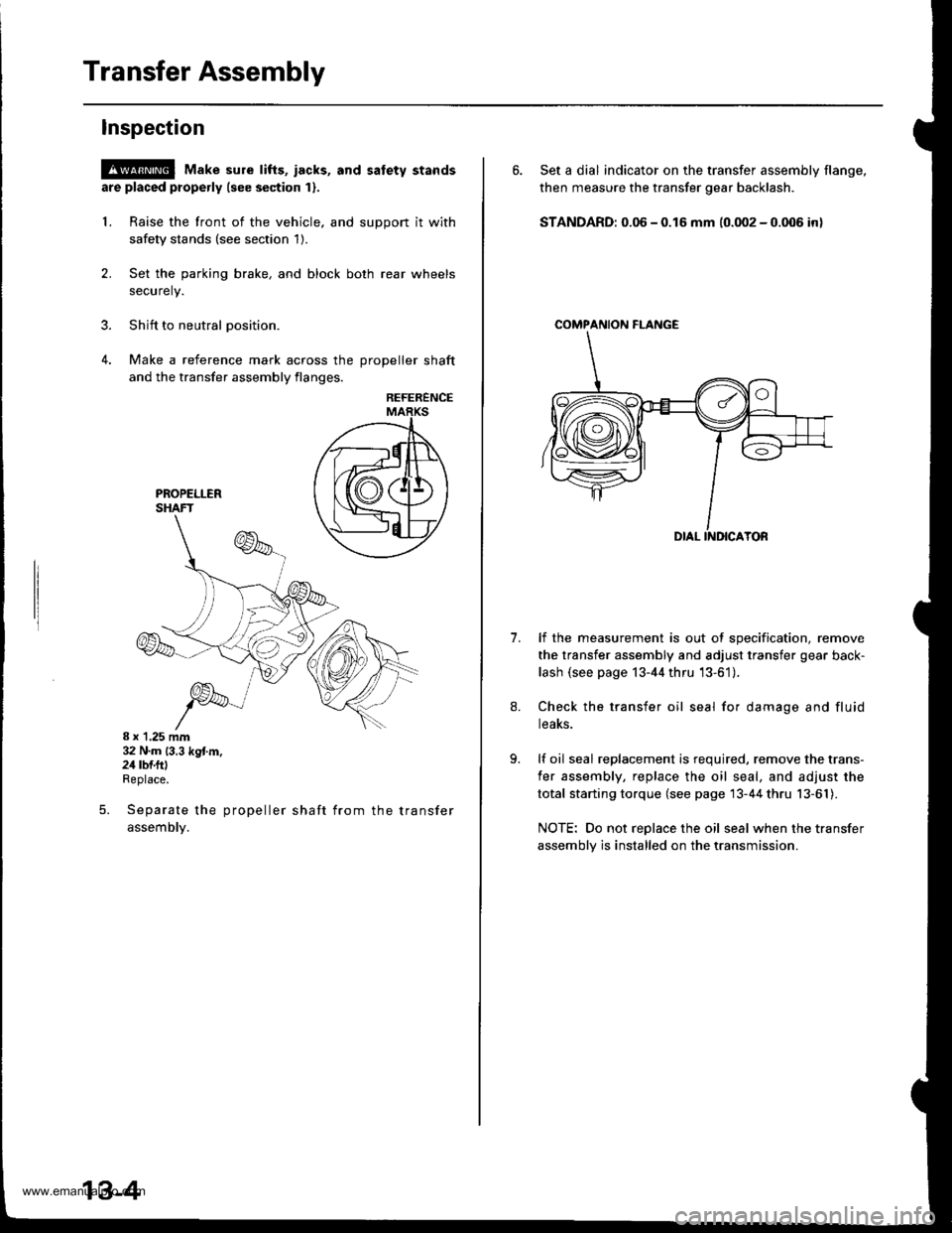
Transfer Assembly
lnspection
@ Make sure tifts, iacks, and satety stands
are placed properly (see section 1).
L Raise the front of the vehicle, and support it with
safety stands (see section 1).
2. Set the parking brake, and block both rear wheels
securely.
3. Shift to neutral oosition.
4. Make a reference mark across the DroDeller shaft
and the transfer assembly flanges,
REFERENCE
8 x 1.25 mm32 N.m (3.3 kg{.m.24 rbf.ftlReplace.
Separate the propeller shaft from the transfer
assemDty.
5.
13-4
6. Set a dial indicator on the transfer assembly flange,
then measure the transfer gear backlash.
STANDARD: 0.06 - 0.16 mm (0.002 - 0.006 in)
COMPAf{ION FI-ANGE
1.lf the measurement is out of specification, remove
the transfer assembly and adjust transfer gear back-
lash (see page 13-44 thru '13-61).
Check the transfer oil seal for damage and fluid
teaKs.
lf oil seal replacement is required, remove the trans-
fer assembly, replace the oil seal, and adjust the
total starting torque (see page 13-44 thru 13-61).
NOTE: Do not replace the oil seal when the transfer
assembly is installed on the transmission.
www.emanualpro.com
Page 444 of 1395
Removal
!@@ Make sure the lifts, i8cks. and safety stands
are placed properly {see section 1}.
1. Raise the front of the vehicle, and support it with
safety stands (see section 1).
2. Set the parking brake, and block both rear wheels
securely.
3. Drain the manual transmission fluid Reinstall the
drain plug with a new sealing washer.
4. Disconnect the heated oxygen sensor (HO2S) con-
nector.
SELF.L(rcKNGNUTReplace.
SELF-LOCKI'{GNUTReplac€.
5. Remove exhaust oipe A.
6. Make reference marks across the propeller shaft
and the transfer assembly flanges'
Separate the propeller shaft from the transfer
assembly flanges,
Remove the rear stiffener, then remove the transfer
assembly.
NOTE: While servicing the transfer assembly, do
not allow dust or other foreign particles to enter the
transmission.
7.
REFEREI{CE i'ARKS
Replace.
Replace.
13-5
www.emanualpro.com
Page 445 of 1395

Transfer Assembly
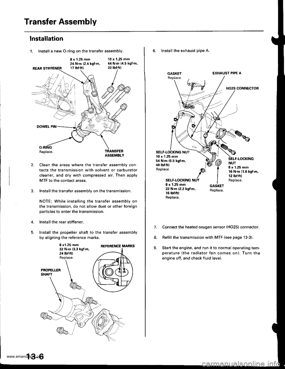
lnstallation
1. Install a new O-ring on the transfer assembly.
8 x 1.25 mm24 N.m (2.4 kgt m,17 rbt.ftl
10 x 1.25 mm44 N.m (4.5 kgJ.m,
2.
DOWEL PIN
Replace.TRANSFEBASSEMBLY
Clean the areas where the transfer assembly con
tacts the transmission with solvent or carburetor
cleaner, and dry with compressed air. Then apply
MTF to the contact areas.
Installthe transfer assembly on the transmission.
NOTE: While installing the transfer assembly on
the transmission, do not allow dust or other foreign
particles to enter the transmission.
lnstall the rear stiffener.
Install the propeller shaft to the transfer assembly
by aligning the reference marks,
8 x1.25 mm32 N.m 13.3 kg{.m,24 tbf.ftl
REFERENCE MARKS
6. Install the exhaust pipe A,
GASKETEXHAUST PIPE A
HO2S CONNECTOR
10 x 1 .25 mm54 N.m (5.5 kgt m,40 tbtfttReplace.
SELF.LOCKING
NUT8 x 1.25 mm16 N.m {1.6 kgf.m,12 tbt.ft)Replace.8 x 1.25 mmzzN.m l2.2kg!-m,16 rbf.trtReplace.
7.Connect the heated oxygen sensor (HO2S) connector.
Relill the transmission with MTF (see page 13-3).
Start the engine, and run it to normal operating tem-
perature (the radiator tan comes on). Turn the
engine off. and check fluid level.
8.
9.
www.emanualpro.com
Page 446 of 1395
Transmission AssemblY
Removal
@FMak. sw. iack" and safety stands are placed propel-
ly, and hoist brackets are attached to collect position
on the engine,
. Apply parking brake and block rear wheels so vehicle
will not roll off stands and lall on you while working
under it.
CAUTION: Use fender covers to avoid damaging painted
surfaces.
1. Disconnect the negative {-) cable first, then the pos-
itive (+) cable from the batterY.
2. Remove the intake air duct and air cleaner houslng
(see section 5).
3. Remove the slave cylinder and clutch hose bracket'
NOTE:
. Do not operate the clutch pedal once lhe slave
cvlinder has been removed.
. Take care not to bend the clutch line.
4. Disconnect the
ground cable.
starter cables and transmission
TRANSMISSIONGROUND CABLE
Disconnect the back-up light switch connector and
wire harness clamP.
(cont'd)
13-7
WIRE HARNESS CLAMP
www.emanualpro.com
Page 449 of 1395
Transmission Assembly
Removal (cont'd)
20. Remove the intermediate shaft.
21.Tie plastic bags over the both ends of the intermedi-
ate shaft. Coat all precision finished surfaces withclean engine oil.
Remove the rear engine stiffene. and clutch hous-Ing cover.
13-10
23. Remove the right front mounvbracket.
RIGHT FRONTMOUNT/BRACKET
Place a jack under the transmission, raise it just
enough to take it off of the mounts, then remove
the transmission mount bracket and transmission
mount.
TRANSMISSION MOUNT
MOUNT BRACKET
www.emanualpro.com
Page 450 of 1395
25. Remove the transmission mounting bolts and the
rear engine mounting bolts.
REAR ENGINE MOUNTING BOLTSReplace.
TRANSMISSION
Pull the transmission away from the engine until it
clears the mainshaft, then lower it on the transmis-
sion jack.
NOTE: Take care not to bend the clutch line.
Remove the starter motor and hose clamp from the
transmission housing.
STARTERMOTOR
28. Remove the release tork boot. release bearing, and
release fork from the clutch housing
RELEASEBEANING
13-1 1
www.emanualpro.com