Page 118 of 1395

Valve Seals
Replacement (cylinder head removal not required)
The procedure shown below applies when using the in-
car valve spring compressor (Snap-on YA8845 with
YA8845-2A 7/8" auachment). Use approved eye protec-
tion.
1. Turn the crankshaft so that the No. 1 and the No. 4
pistons are at top dead center (TDC).
2. Remove the cylinder head cover.
3. Remove the distributor.
4. Loosen and disconnect the timing belt from the
camshaft pulleys.
5. Remove the camshaft holder bolts. then remove the
camshaft holders, the camshafts and rocker arms.
lntake Valve Seals
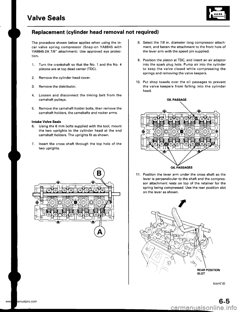
6. Using the 6 mm bolts supplied with the tool, mount
the two uprights to the cylinder head at the end
camshaft holders. The uprights fit as shown.
7. Insert the cross shaft through the top hole of the
two uprights,
at.
9.
Select the 7/8 in. diameter long compressor attach-
ment, and fasten the attachment to the front hole of
the lever arm with the speed pin supplied.
Position the piston at TDC, and insen an air adaptor
into the spark plug hole. Pump air into the cylinder
to keep the valve closed while compressing the
springs and removing the valve keepers.
10. Put shop towels over the oil passages to prevent
the valve keepers from falling into the cylinder
head.
Position the lever arm under the cross shaft so the
lever is perpendicular to the shaft and the compres-
sor attachment rests on top of the retainer for the
spring being compressed. Use the rear position slot
on the lever as shown,
't1.
OIL PASSAGE
OIL PASSAGES
(cont'd)
6-5
www.emanualpro.com
Page 119 of 1395

Valve Seals
12.
Replacement (cylinder head removal not requiredl (cont'dl
Using an upward motion on the lever arm, compress
the valve spring and remove the keepers from the
valve stem. Slowly release pressure on the spring.
Repeat step 11 for the other valve in that cylinder.
Remove the valve seals (see page 6-24).
Installthe valve seals (see page 6-29).
lnstall the springs, the retainers and the keepers in
reverse order of removal.
'17. Repeat steps 9 to 16 for the other three cylinders.
Exhaust valve Seals
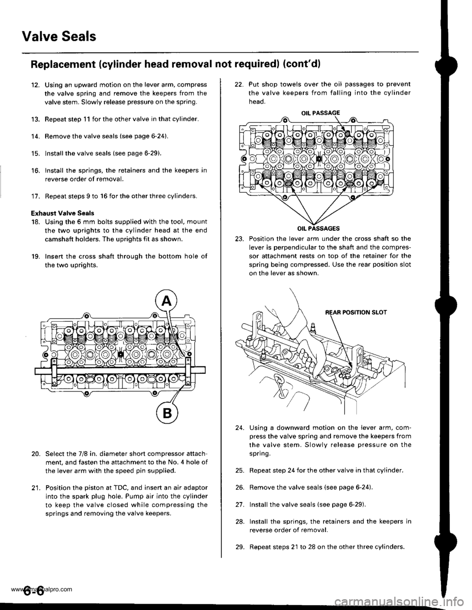
18. Using the 5 mm bolts supplied with the tool, mount
the two uprights to the cylinder head at the end
camshaft holders. The uprights fit as shown.
19. Insert the cross shaft through the bottom hole of
the two uprights.
Select the 7/8 in. diameter short compressor attach
ment, and fasten the attachment to the No. 4 hole of
the lever arm with the speed pin supplied.
Position the piston at TDC, and insert an air adaptor
into the spark plug hole. Pump air into the cylinder
to keep the valve closed while compressing the
springs and removing the valve keepers.
13.
14.
15.
16.
20.
t1
22. Put shop towels over the oil passages to prevent
the valve keepers from falling into the cylinder
neao.
23. Position the lever arm under the cross shaft so the
lever is perpendicular to the shaft and the compres-
sor attachment rests on top of the retainer for the
spring being compressed. Use the rear position slot
on the lever as shown.
Using a downward motion on the lever arm, com-
press the valve spring and remove the keepers from
the valve stem. Slowly release pressure on the
spring.
Repeat step 24 for the other valve in that cylinder.
Remove the valve seals (see page 6-24).
Install the valve seals (see page 6-29).
Install the springs, the retainers and the keepers in
reverse order of removal.
Repeat steps 21 to 28 on the other three cylinders.
24.
21.
28.
29.
o-o
www.emanualpro.com
Page 161 of 1395
Piston Pins
lnstallation
The arrow must face thetiming belt side ot theengine and the connectingrod oil hole must face therear of the engine.
CONNECTING ROOotL Hor.E
1. Adjust the length B of the piston pin driver and shaft.
B: 49.70 mm (1.957 in)
PISTON PIN DRIVER SHAFT0t973 - P€qxtlo
Place the piston on the
pin in with a hydraulic
recessed portion of the
on the piston base head.
ffi*r,"ron'nl
PILOT COLLAROTLAF - PF3O1(x'
PISTON PIN BASE INSERT07GAF - PH6o3ttO
PISTON BASE HEADOTHAF - PL2O102
PISTON BASE07973 - 6670500
piston base and press the
press. Make sure that the
piston aligns with the lugs
7-15
www.emanualpro.com
Page 170 of 1395
Oil Seals
Installation (cont'dl
4. l/easure the flywheel-end seal thickness and the oil
seal housing depth. Using the special tool, drive theflywheel end seal into the rear cover to the point
where the clearance between the bottom of the oil
seal and the right side cover is 0.5 - 0.8 mm (0.02 -
0.03 in) (see page 7-19). Align the hole in the driverattachment with the pin on the crankshaft.
DRIVERATTACHMENT76x80mm07948 - 5800101Install sealwith thenumber side facingout,
<:
7 -24
www.emanualpro.com
Page 242 of 1395
System Description
System Gonnectors lDash and Floor] -'97 Model
MAIN WIREHARNESS
DASHBOARD WIREHANNESS
REAR HEATED OXYGENSENSOR SUA HARNESS
WIRE HARNESS
www.emanualpro.com
Page 256 of 1395
System Description
\System Connectors [Dash and Floorl -'98 - 00 Models
DASHBOARD WIREHART{ESS
REAR HEATED OXYGENSENSOR SUBHAR ESS
Ita|l{ wtREHARIIIESS
LEFT SIDEWIRE HAR ESS
11-54
www.emanualpro.com
Page 337 of 1395
![HONDA CR-V 1998 RD1-RD3 / 1.G Workshop Manual
Vehicle Speed Sensor (VSSI
lPosoo-]-. |posol l-
97 modol:
The scan tool indicates Diagnostic Trouble Code {DTC} P0500*�or P0501*r: A range/perfor-
mance in the Vehicle Speed Sensor (VSS) circuit. HONDA CR-V 1998 RD1-RD3 / 1.G Workshop Manual
Vehicle Speed Sensor (VSSI
lPosoo-]-. |posol l-
97 modol:
The scan tool indicates Diagnostic Trouble Code {DTC} P0500*�or P0501*r: A range/perfor-
mance in the Vehicle Speed Sensor (VSS) circuit.](/manual-img/13/5778/w960_5778-336.png)
Vehicle Speed Sensor (VSSI
lPosoo-]-'. |posol l-'
'97 modol:
The scan tool indicates Diagnostic Trouble Code {DTC} P0500*'�or P0501*r: A range/perfor-
mance in the Vehicle Speed Sensor (VSS) circuit. * I ; A/T*2i Mfi
FCM CONNECTORS
A t32Pl
LG1(BRN/BLK)
NOTE: Do not use the engine to turn thofront wheels with th6 rear wheels on theground. The 4WD system will engage andthe vehicle will suddenlv Iurch forward.
Wire side ot female terminals
LGl
{BRN/BLKI
(cont'd)
11-135
The MIL hes boen roported on.DTC m501 is 3tor€d.
Problom verificetion:1. Test'drive the vohicle.2. Check the vehicle speed withthe scan tool,
lntormittent tailure, rystom b OKat thia timo. Chock tor poor con-nection3 or 10o3o wires rt C129lvss) .nd rr rhe Pcfr4,
ls the correct speed indicated?
Chock for an open in tho PiCM:1. Turn the ignition switch OFF.2. Block the rear wheels and setthe parking brake.3. Jack up the lront of the vehicleand support it with saletystands.4. Turn the ignition switch ON (ll).
5. Elock the right front wheel andslowly rotate the left trontwheel by hand.6. Measure voltage betweenPCM connector terminals C18and A9.
Substitulc a known-good PCMand .och6ck. It symptom/indicd.tion go.a away, .cplaco tho origi-nel FCM.
Doesthe voltage pulse 0 Vand 5 V or battery voltage?
Check for a .hort in the PCM:L Turn the ignition switch OFF.2. Disconnect the PCM con'nector C (31P).
3. Turn the ignition switch ON (ll).
4. Elock the right front wheeland slowly rotate the left front
5. Measure vohage between PCMconnector terminals C18 andA9.
Substituto e known-good PCMand rochock. f rymptom/indica-tion goos rwry, roplsc. tho origi-nalFCM.
Doesthe voltage pulse 0 Vand 5 V or battery voltage?
- Repair short in the wirebetween the PCM lC18l,cruise control unit, speodo-meter, and VSS,- Repair opon in the wirebetween the PCM {C181 .ndrhe vss.- f wire is OK. tost lho VSS l3oosoction 231.
www.emanualpro.com
Page 338 of 1395

PGM-FI System
Vehicle Speed Sensor (VSSI {cont'd}
'98 - 00 models:
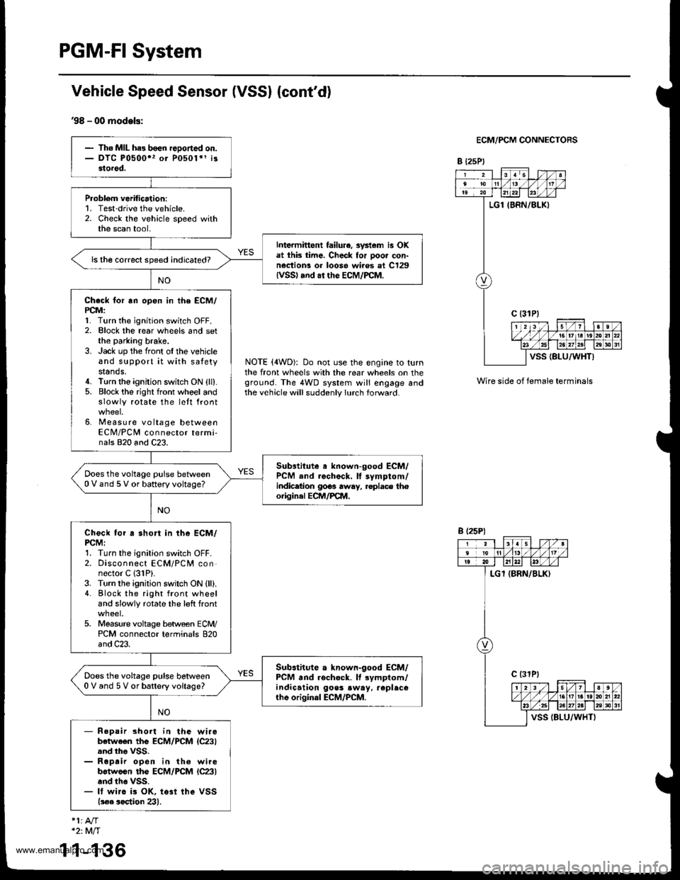
ECM/PCM CONNECTORS
B t25Pl
NOTE (4WD): Do not use the engine to turnthe front wheels with the rear wheels on theground. The 4WD system will engage andthe vehicle will suddenly lurch forward.
Wire side of female terminals
- The MIL ha3 been reDoned on.- DTC P0500" or P0501*1 i33torod.
Probl6m verification:1. Test-drive the vehicle.2. Check the vehicle speed withthe scan tool,
Intermittont failu.e, svstem is OKat thk time. Check for poor con-nection! or loose wiros at C129lvss) .nd ar the EcM/PcM.
ls the correct speed indicated?
Check for rn open in the ECM/PCM:l� Turn the ignition switch OFF.2. Elock the rear wheels and setthe parking brake.3. Jack up the front oI the vehicleand support it with satetystands.4. Turn the ignition switch ON {ll}.5. Block the right front whoel andslowly rotate the lett front
6. Measure voltage betweenECM/PCM connector termi-nals 820 and C23.
Substitute a known-good ECM/PCM and rochock. ll symptom/indicetion 9063 away, .oplace th€origin.l ECM/PCM.
Does the voltage pulse between0 V and 5 V or battery voltage?
Check for a short in the ECM/PCMI1. Turn the ignition switch OFF.2. Disconnect ECM/PCM connector C 131P).3. Turn the ignition swilch ON {ll).4. Block the right front wheeland slowly rotate the left front
5. Moasure voltage between ECM/PCM connector terminals 820and C23.
Sub.titute a known-good ECM/PCM and rschock. It rymptom/indication goos .w.y. replecerhe original ECM/PCM.
Does the voltage pulse betlveen0 V and 5 V or battery voltage?
- R.pair short in the wirobetwe€n the ECM/PCM lC23).nd tho VSS.- Roprir open in th6 wirebotweon the ECM/PCM lc23land th6 vss.- It wirc is OK, te3t ihe VSS(!€e soetion 23).
B (25P)
1
*2:Mft
1-136
www.emanualpro.com