Page 1207 of 1395

BLKG401
GroundWir€ ColorComponent or Circuits Grounded
ABS indicator circuit
ABS control unit
Ashtray light
A/T gear position indicator dimming circuit
Brake fluid level switch
Clock ('98 - 00 models)
Clutch inrerlock switch (M/T)
Clutch switch (Mff)
Cruise main switch
Cruise indicator circuit
Cruise control unit
Dash lights brightness controller
Data iink connector
Daytime running rights control unit (Canada)
Front accessary socket
Gauge and indicators
Heater control panel
lgnition key light control unit ('97 model)
lgnition key switch
Integrated control unit
Interlock control unit (Ay'T)
Parking pin switch {A,/T)
Power window relay
Rear accessary socket relay
Bear window defogger relay
Rear window wiper control unit ('97 model)
Service check connector
Spotlights
SRS indicator circuit
Turn signal/hazard relay
Windshield wiper motor
Windshield wiper/washer switch- plus everything grounded through G402
ABS control unit
Blower motor relay
Blower motor high relay
ELD unit (USA)
Power transistor- plus everything grounded through G401
BLKG402
{cont'd)
23-47
www.emanualpro.com
Page 1224 of 1395
Integrated Gontrol Unit
Circuit Diagram -'97 Model
UNDER.HOOD FUSEi RELAY 8OXBATTEFYI No.4' {'004) \0.d2'40A) |
cr*"
l__*l;;T
w_T ELK +!v_T
I H-uTr.r--i=r-
GFNi BLK
lo,,.h WINDSHIELD( il) WASHEB
Y
SWITCH
WHTiBLK
I
l-IVWHT]BLK WINDSHIELDI WASHERI MOTOB
WINDSHIELD WIPER/WASHEF 9WTTCH ,
OFF/INT INT
VV
tltltl
tl
BLUMHT
VWINDSHIELDWIPERMOTOR(As)
ag
3
YEL
RED/BLU
DRIVER'SSEATBELTswtTcHf CLOSED r Unbuckled )(OPEN :Buckled -.1
BEMINDEBLIGHT(r 4w)
BLK
G401
BL(I-tr-l
G552
23-64
tGNITtON SW lCrl
BLKryEL
KEY.IN/SEAT BELTand LIGHTS-ONBEMINDER CIRCUITNTERMITTENT WIPER RELAY CIRCUlT
www.emanualpro.com
Page 1226 of 1395
Integrated Control Unit
UNOER,HOOD FUSE/BELAY 8OX
N0.41 (100A) N0.42 (40A)
Circuit Diagram -'98 - 00 Models
EATTERY
@*"WHT/BLK -....+ WHT
WHT/RED
IJNDER DASH FUSEi BELAY BOX
WINDSH ELD W PER/gsHERlIrTcH .
OFF/ NT INT
f7 f7
tltl
tl
tlBLU/BLK YEUBLU
GRN/BLK
lo/.Fn WINDSHIELD( il) WASHEF
Y
SWITCH
WHT/BLK
REASWINDOWWIPERMOTOR
f7
ILT GRN
t,,
-9
INTEGFATED coNTsoL UNIT I 85 I 83
23-66
8LK
G401G402
WHT/BLKWINDSHIELDWASHEFMOTOR
INTERIT,IITTENT WIPER RELAY CIRCUITNEAF WINDOW INTERMITTENTWIPER RELAY CIRCUIT
www.emanualpro.com
Page 1229 of 1395

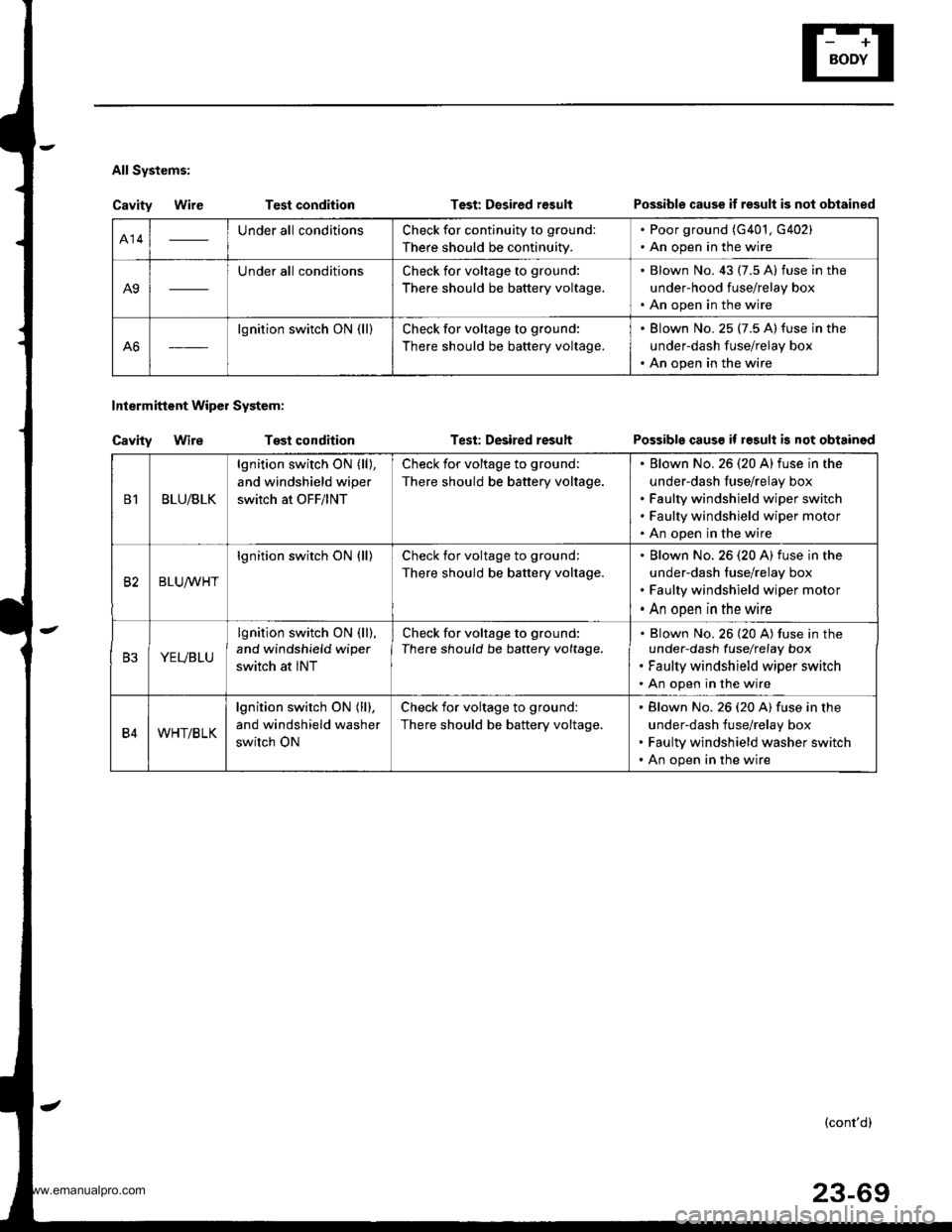
All Systems:
Cavity WireTest condition
Tost condition
Test: Desired r€sult
Test: Desired result
Intermittent Wipol System:
Cavity Wire
Possible cause if result is not obtained
Possible causs if result is not obtained
414Under all conditionsCheck for continuity to ground:
There should be continuity.
. Poor ground (G401, G402). An open in the wire
A9
Under all conditionsCheck for voltage to ground:
There should be battery voltage.
. Blown No. 43 (7.5 A) fuse in the
under-hood fuse/relay box. An open in the wire
A6
lgnition switch ON (ll)Check for voltage to ground:
There should be battery voltage.
. Blown No. 25 (7.5 A)fuse in the
underdash fuse/relay box. An open in the wire
B1BLU/BLK
lgnition switch ON (ll),
and windshield wiper
switch at OFF/lNT
Check for voltage to ground:
There should be battery voltage.
Elown No. 26 (20 A)fuse in the
under-dash fuse/relay box
Faulty windshield wiper switch
Faulty windshield wiper motor
An open in the wire
82BLUrur'HT
lgnition switch ON (ll)Check for voltage to ground:
There should be battery voltage.
Blown No.26 (20 A) fuse in the
under-dash fuse/relay box
Faulty windshield wiper motor
An open in the wire
B3YEVBLU
lgnition switch ON (ll),
and windshield wipe.
switch at INT
Check for voltage to ground:
There should be battery voltage.Blown No. 26 (20 A) tuse in theunder-dash fuselrefay box
Faulty windshield wiper switch
An open in the wire
B4WHT/BLK
lgnition switch ON (ll),
and windshield washer
switch ON
Check for voltage to ground:
There should be battery voltage.
Blown No. 26 (20 A) fuse in the
under-dash fuse/relay box
Faulty windshield washer switch
An open in the wire
(cont'd)
23-69
www.emanualpro.com
Page 1274 of 1395
Wipers/Washers
Component Location Index
SRS components are located in this area. Review the SRs component locations, precautions, and procedures in the s6ssection (24) before performing repairs or service.
REAB WINDOW WIPER MOTOBT€st, page 23-120WPSR/WASHER SWITCHTest. page 23- l't9
REAR WINDOW WIPERCONTROL UNlT 137 mod.llInput test. page 23-118
WINDSHIELD WIPER MOTORTost, page 23-119
UNDER.DASH FUSE/RELA
INTERMITTENT W|PEN RELAYCIBCUIT, REAR WINDOW INTERMTNENTwlPER RELAY CIBCUIT l'98 - 0O mod.t.lBOX (ln the integrated control unit)Input test, page 23-68
23-114
-
n
tff
www.emanualpro.com
Page 1275 of 1395
UNDEB,DASHFUSENELAY BOXIGNITON SWITCH
l-Circuit Diagram {Windshieldl
@*"
BLUiBLK
YEUBLU
WHTiBLK
l-
BLK
I
I
I
I_L
G401G402
23-115
8LK
G401G402
BLK
G401G402
UNDEB.HOOD FUSE/NELAY BOX
N0.41 (1004) N0.42 {40A)
INTEGEATEDCONTFOLUNIT
/ Has bui[-in \I inlermiltenl I wiper relay /
www.emanualpro.com
Page 1279 of 1395

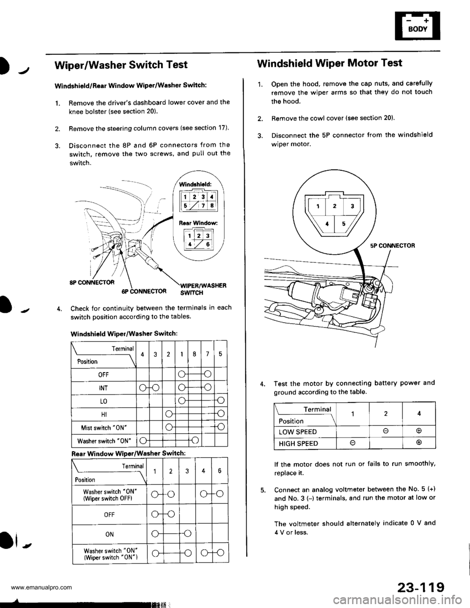
Wiper/Washer Switch Test
Windshield/ReEr Window Wiper/Washer Switch:
1. Remove the driver's dashboard lower cover and the
knee bolster (see section 20).
2. Remove the steering column covers {see section 17)
3. Disconnect the 8P and 6P connectors from the
switch, remove the two screws, and pull out the
switch.
J-
lind3hi.ld:
tilt-rltl
IEZIA
Raar Window:
11 2 3
I t-7 al
ll -
Check for continuity betlveen the termlnals in each
switch position according to the tables.
Windshield Wiper/Washer Switch:
Terminal
P*t-
---__\432175
OFFoo
INToooo
LOoo
HIoo
Mist swhch "0N"oo
Washer switch "0N"oo
Rear Window Wipsr/Washer Switch
Teminal
ti'"
---\12346
Washer switch '0N'
(wiper switch oFFlG-oG-o
OFFG-o
ONGo
Washer switch "ON'
(Wiper switch "0N"1G-oG-o
-rmxft
23-119
1.
Windshield Wiper Motor Test
Open the hood, remove the cap nuts, and caretully
remove the wiper arms so that they do not touch
the hood.
Remove the cowl cover (see section 201.
Disconnect the 5P connector trom the windshield
wiper motor.
Test the motor by connecting battery power and
ground according to the table.
lf the motor does not tun or fails to run smoothly,
replace it.
Connect an analog voltmeter between the No. 5 (+)
and No. 3 (-) terminals, and run the motor at low or
high speed.
The voltmeter should alternately indicate 0 V 8nd
4 V or less.
Terminal
;fi;"
-l4
LOW SPEED@
HIGH SPEED@
www.emanualpro.com
Page:
< prev 1-8 9-16 17-24