Page 3 of 1395
General lnformation
Chassis and Paint Codes ....................... 1-2
ldentification Number Locations ......... 1-10
Warning/Caution Label Locations ....... 1-11
Under-hood Emissions Control
Label .......... ..................... 1-15
Lift and Support Points
Lift and Safety Stands ....................... 1-19
Floor Jack ....................... 1-20
Towing .........1-21
Service Precautions
Pafts Marking Locations ..,................. 1-22
Precautions for Real-time 4WD
(Four-wheel Drivel ......... ................. 1 -23
www.emanualpro.com
Page 4 of 1395
U.S. 1997 Model
Vehicle ldentification Number
JHLRD184*VC000001
JHL: HONDA MOTOR CO., LTD
HONDA, Multipurpose
Passenger Vehicle (MPV)
line, Body and Engine Type
RDl: CR V/82084
Body Type and Transmission Type
8: 5-door/4-soeed Automatic
Vehicle Grade (Series)
4: LX
5: LX (with ABS)
Check Digit
Model Year
Vt 1997
C: Saitama Factory in Japan (Sayama)
Chassis and Paint Codes
(o
COLOR LABEL
B-84P
NH-552M
NH-592P
R-94
Supermarine Blue Pearl
Cypress Green Pearl
Sebring Silver Metallic
Flamenco Black Pearl
San Marino Red
Vehicle ldentif ication Number
and Federal Motor Vehicle
INT. COLOR
WPE F
EXT. COLOR
B-84P
KA S2B A1 C
1-2
to
www.emanualpro.com
Page 6 of 1395
Chassis and Paint Codes
U.S. 1999 Model
Vehicle ldentification Number
JHLRDIT4*XC000001
JHL: HONDA MOTOR CO., LTD
HONDA. Multipurpose
RDlt CR-vlB20Z2
RD2t CR-V1B2OZ2
Body Type and Transmission Type
7: 5-door/5-speed Manual
8: 5-door/4-spsed Automatic
4: LX
6: Ex
Chock Digit
Model Year
X: 1999
C: Saitama Factory in Japan (Sayama)
B2OZ2:2.0 | DOHC Sequential Multiport
Fuel-injected engine
MDLA: 4-speed Automatic
MDMA: 4-speed Automatic
SBXM: s-speed Manual
MDLA: 2000001-
MDMA: 1000001-
SBXM: 2000001-
B-84P
B-92P
G.95P
NH-578
NH-552M
R,81
Supermarine Blue Pearl
Nighthawk Black Pearl
Clover Green Pearl
Taffeta White
Sebring Silver Metallic
Milano Red
Vehicle ldentification Number
and Canadian Motor VehicleCOLOR LABEL
INT. COLOR
TYPE F
EXT. COLOR
B.84P
KA S2B A1 C
1-4
www.emanualpro.com
Page 8 of 1395
Chassis and Paint Codes
Canada 1997 Model
JHLRD185* V C 800001
HONDA MOTOR CO., LTD
HONDA, Multipurpose
Passenger Vehicle (MPV)
Line, Body and Engine Type
RDl: CR-V/B2084
Body Typ€ and Transmission Typ€
8: s-door/4-soeed Automatic
C: Saitama Factory in Japan (Sayama)
B20g4t 2.0 | DOHC Seouential MultiDort
Fuel-injected engine
MDMA- 1000001
MDMA: 4-speed Automatic
SDMA: 4-speed Automatic
Supermarine Blue Pearl
Cypress Green Pearl
Sebring Silver Metallic
Flamenco Black Pearl
San Marino Red
B-84P
G-82P
NH-552M
NH-592P
R-94
Vehicle ldentification Number
and Canadian Motor Vehicle
Saf ety Standard Certifi cation.
COLOR LABEL
INT. COLOR
TYPE F
EXT. COLOR
B-84P
KC S2B C2 C
1-6
www.emanualpro.com
Page 10 of 1395
Canada 1999 Model
Vehicle ldentification Number
JHL RDl T 4*XC800001
JHL: HONDA MOTOR CO., LTD
HONDA, Multipurpose
Passen0er Vehicle {MPV)Line, Body and Engin6 Type
RD1: CB-Y/B2OZ2
Eody Typ6 and Transmi$ion Type
7: 5-door/5-speed Manual
8: s-door/4-speed Automatic
4: LX
5: EX
Chock Digit
Model Yeal
X: 1999
C: Saitama Factory in Japan {Sayama)
Chassis and Paint Codes
COLOR LABEL
B20Z2i 2.0 I DOHC Sequential Multiport
Fuel-injected engine
MDMA: 4-speed Automatic
SBXM: s-speed Manual
B-84P
a-92P
G.95P
NH.552M
R-81
Supermarine Blue Pearl
Nighthawk Black Pearl
Clover Green Pearl
Sebring Silver Metallic
Milano Red
Vehiclo ldentification Number
and Canadian Motor Vehicle
Safety Standard Certification.INT. COLOR
TYPE F
EXT. COLOR
B-84P
KC S2B C2 C
1-8
www.emanualpro.com
Page 55 of 1395

Starting System
Starter Test
NOTE: The air temperature must be between 59 and'100'F (15 and 38"C) before testing.
Recommended Procedure:
. Use a staner system tester.
. Connect and operate the equipment in accordance
with the manufacturer's instructions.
. Test and troubleshoot as described.
Alte.nate Procedure:
. Use the following equipment:- Ammeter, 0 - 400 A- Voltmeter, 0 - 20 V (accurate within 0.1 volt)
Tachometer,0 - 1,200 rpm
. Hook up a voltmeter and ammeter as shown.
NOTE: After this test, or any subsequent repair. reset
the ECM/PCM to clear any codes (see section 1 1).
Check the Starter Engagement:
'1. Remove the No. 44 (15 A) fuse from the under-hood
fuse/relay box.
2. Turn the ignition switch to START (lll) with the shift
lever in E or E position (A/T) or with the clutch
pedal depressed {M/T). The starter should crank the
eng ine.
. lf the starter does not crank the engine, go to
step 3.
. lf it cranks the engine erratically or too slowly, go
to "Check for Wear and Damage" on the next
page.
NEGATIVE TERMINAL
4.
5.
6.
7.
8.
Check the battery, battery positive cable, ground.
staner cut relay, and the wire connections for loose-
ness and corrosion. Test again.
lf the staner still does not crank the engine, go to
step 4.
Unplug the connector (BLK /VHT wire and solenoid
terminal) from the starter.
Connect a jumper wire from the baftery positive (+)
terminal to the solenoid terminal.
The starter should crank the engine.
. lf the starter still does not crank the engine,
remove it, and diagnose its internal problem.
. lf the starter cranks the engine, go to step 6.
Check the ignition switch (see section 23).
Check the starter cut relay {see section 23}.
Check the IVT gear position switch (A/T) or the clutch
interlock switch (M[).
Check for an open in the wire between the ignition
switch and starter.
(cont'd)
4-5
www.emanualpro.com
Page 154 of 1395

Main BearingsConnecting Rod Bearings
Selection
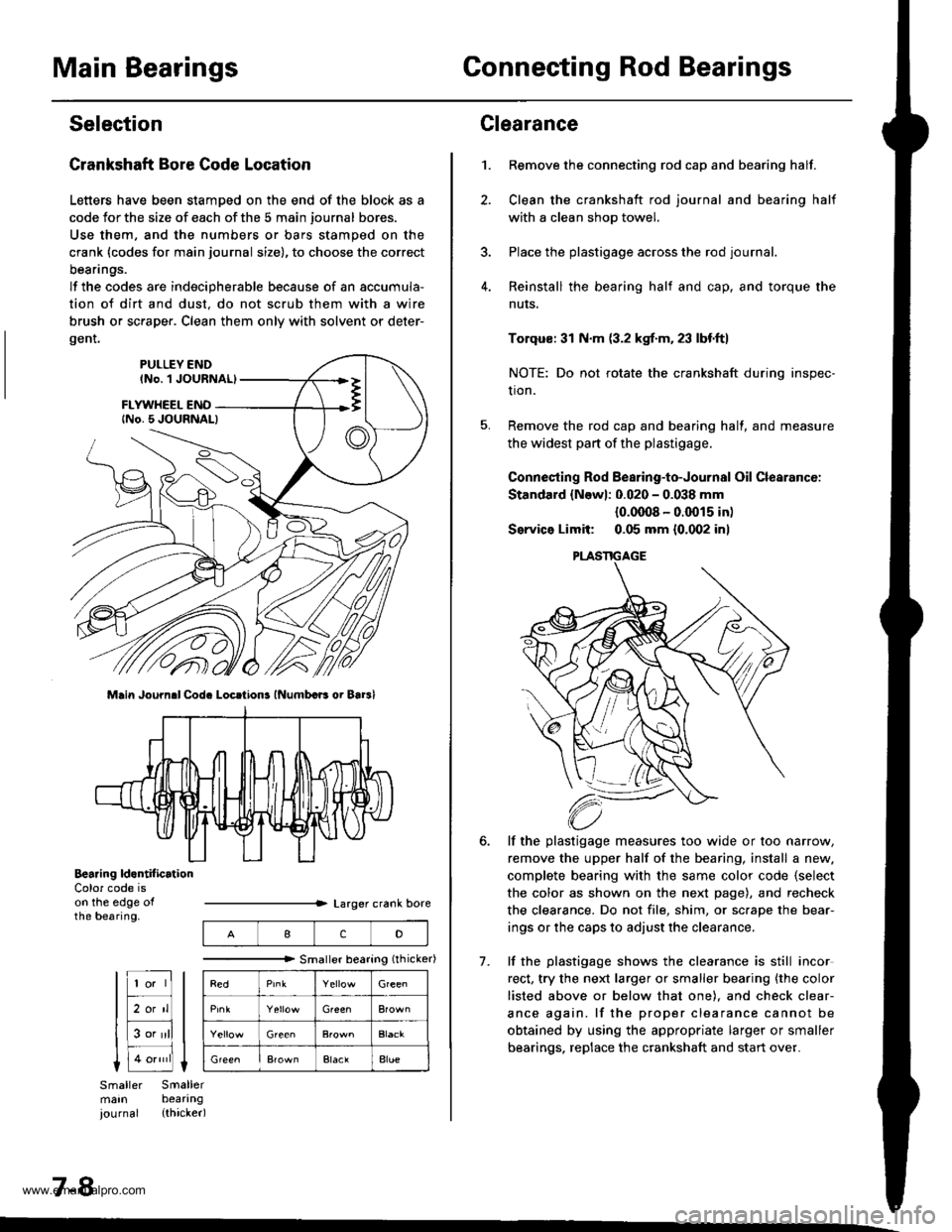
Crankshaft Bore Code Location
Letters have been stamDed on the end of the block as a
code Jor the size of each of the 5 main journal bores.
Use them, and the numbers or bars stamped on the
crank (codes for main journal size), to choose the correct
beanngs.
lf the codes are indecipherable because of an accumula-
tion of dirt and dust. do not scrub them with a wire
brush or sc.aper. Clean them only with solvent or deter-
gent.
Main Journ.l Cod. Locrtions lNumbcB oi Bar3l
Bearing ld.ntif icrtionColor code ison the edge ofthe bearing.
7-8
IcD
"""""""" Smallerbearing(rhicker)
Green
Green
ElaclAlue
Clearance
Remove the connecting rod cap and bearing half.
Clean the crankshaft rod journal and bearing half
with a clean shop towel.
Place the plastigage across the rod journal.
Reinstall the bearing half and cap, and torque the
nuts.
1.
7.
Torqus: 31 N.m (3.2 kgf.m. 23 lbf.ft)
NOTE: Do not rotate the crankshaft during inspec-
tion.
Remove the rod cap and bearing half, and measure
the widest part of the plastigage.
Connesting Rod Bearing-to-Journal Oil Clearancc:
Standard {Newl: 0.020 - 0.038 mm
{0.0008 - 0.0015 in)
Service Limit: 0.05 mm {0.002 inl
lf the plastigage measures too wide or too narrow,
remove the upper half of the bearing, install a new.
complete bearing with the same color code {select
the color as shown on the next page), and recheck
the clearance. Do not file, shim, or sc.ape the bear-
ings or the caps to adjust the clearance.
lf the plastigage shows the clearance is still incor
rect, try the next larger or smaller bearing {the color
listed above or below that one). and check clear-
ance again. lf the proper clearance cannot be
obtained by using the appropriate larger or smaller
bearings. replace the crankshaft and start over.
PLASTIGAGE
www.emanualpro.com
Page 155 of 1395

Pistons and
Crankshaft
Selection
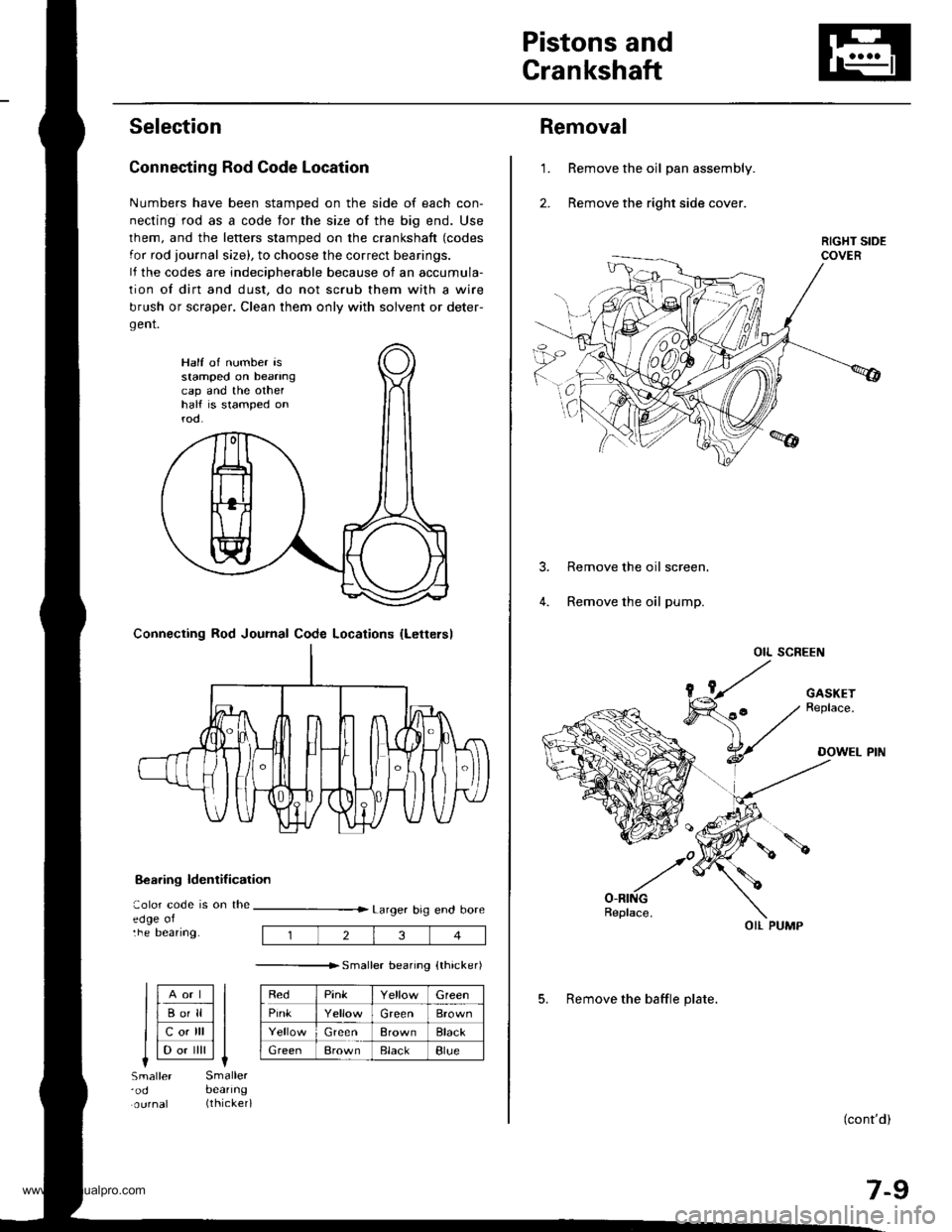
Connecting Rod Code Location
Numbers have been stamped on the side of each con-
necting rod as a code for the size of the big end. Use
lhem, and the letters stamped on the crankshaft (codes
for rod journal size), to choose the correct bearings.
lf the codes are indeciDherable because of an accumula-
tion of dirt and dust, do not scrub them with a wire
brush or scraper. Clean them only with solvent or deter-
gent.
8€aring ldentif ication
aolor code is on theedge oltne Deanng.
Larger big end bore
---------------r. sma er bearino {thicker)
RedPinkGreen
PinkGreenBrown
GreenBrownBlack
GreenBrownElackBlue
Half of number isstamped on beanngcap and the othelhalf is stamped onrod.
Connecting Rod Journal Code Locations {Lettersl
llAort ll
llBo'll ll
llcotrll ll
I l-.. ilril It-lSmaller'odSmallerbeanng(thicker)
234
Removal
Remove the oil pan assembly.
Remove the right side cover.
1.
Remove the oil screen.
Remove the oil pump.
OIL SCREEN
(cont'd)
7-9
OIL PUMP
5. Remove the baffle plate.
www.emanualpro.com