1998 HONDA CR-V ESP
[x] Cancel search: ESPPage 887 of 1395
Power Steering Gearbox
13.
Reassembly (cont'd)
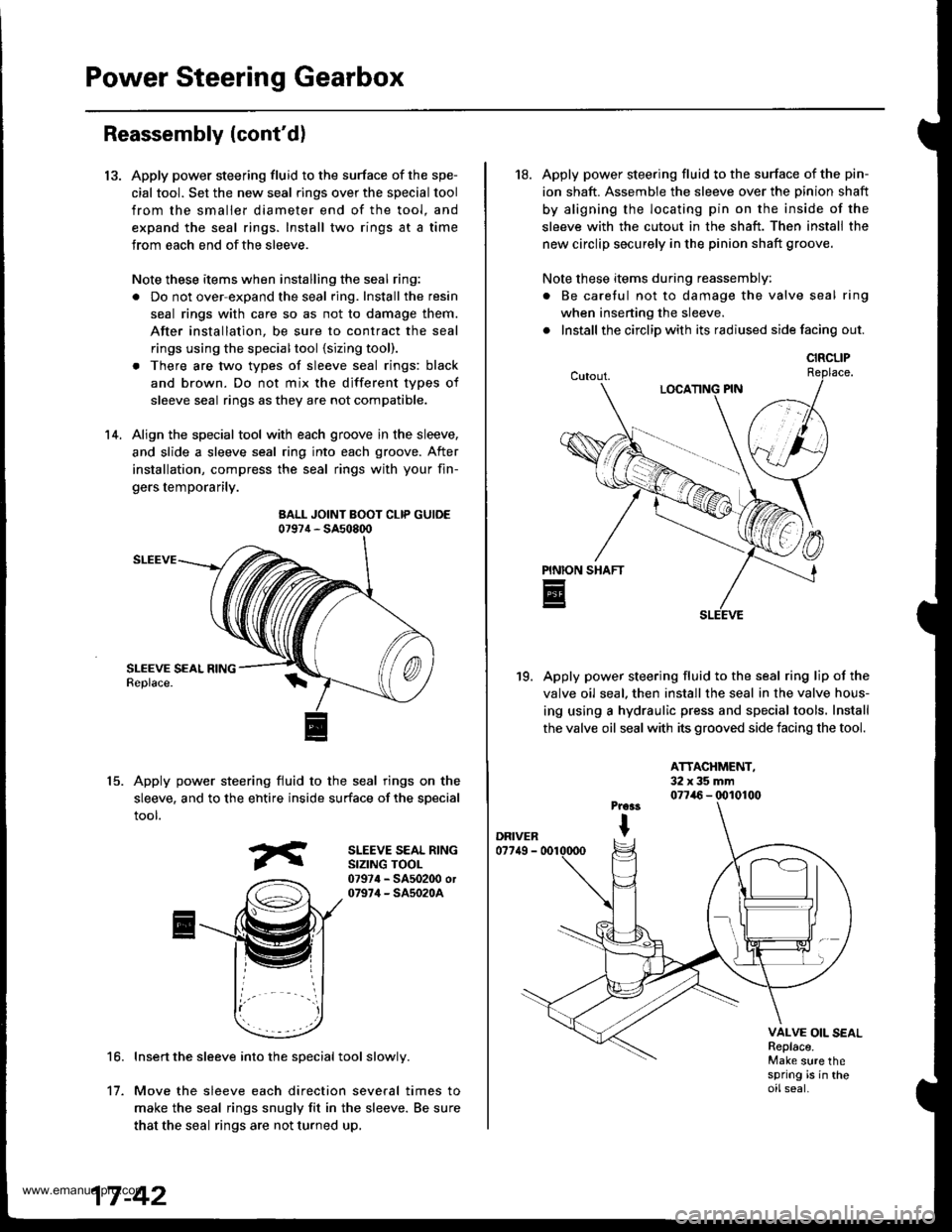
Apply power steering fluid to the surface of the spe-
cial tool. Set the new seal rings over the special tool
from the smaller diameter end of the tool. and
expand the seal rings. Install two rings at a time
Jrom each end ofthe sleeve.
Note these items when installing the seal ring:
. Do not over-expand the seal ring. Install the resin
seal rings with care so as not to damage them.
After installation, be sure to contract the seal
rings using the specialtool {sizing tool).
. There are two types of sleeve seal rings: black
and brown. Do not mix the different types of
sleeve seal rings as they are not compatible.
Align the special tool with each groove in the sleeve,
and slide a sleeve seal ring into each groove. After
installation, compress the seal rings with your fin-
gers temporarily.
BALL JOINT BOOT CLIP GUIDE07974 - SA508q)
SLEEVE
Apply power steering fluid to the seal rings on the
sleeve, and to the ehtire inside surface of the special
tool.
14.
15.
SLEEVE SEAL RINGSIZING TOOL07974 - SA502O0 or07974 - SA5020A
16.Insert the sleeve into the special tool slowly.
Move the sleeve each direction several times to
make the seal rings snugly fit in the sleeve. Be sure
that the seal rings are not turned up,
't1.
18. Apply power steering fluid to the surface of the pin-
ion shaft. Assemble the sleeve over the Dinion shaft
by aligning the locating pin on the inside of the
sleeve with the cutout in the shaft. Then install the
new circlip securely in the pinion shaft groove.
Note these items during reassembly:
. Be caretul not to damage the valve seal ring
when inserting the sleeve.
. Install the circlip with its radiused side facing out.
Apply power steering fluid to the seal ring lip of the
valve oil seal. then install the seal in the valve hous-
ing using a hydraulic press and special tools. Install
the valve oil seal with its grooved side facing the tool.
19.
ATTACHMENT,32x35mm077i16 - (x)10100
VALVE OIL SEALReplace.Make sure thespring is in theoilseal.
CIRCLIP
www.emanualpro.com
Page 889 of 1395
Power Steering Gearbox
Reassembly (cont'dl
Stecring Rack R8assembly
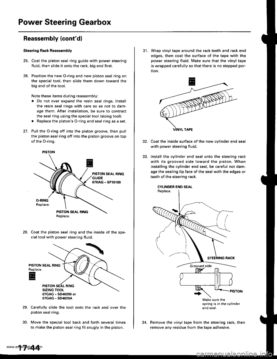
25. Coat the piston seal ring guide with power steering
fluid, then slide it onto the rack, big end first.
26. Position the new O-ring and new piston seal ring on
the sDecial tool, then slide them down toward the
big end of the tool.
Note these items during reassembly:
a Do not over expand the resin seal rings. Install
the resin seal rings with care so as not to dam-
age them. After installation, be sure to contract
the seal ring using the special tool (sizing tool).
a Replace the piston's O-ring and seal ring as a set.
27. Pull rhe O-ring off into the piston groove, then pull
the piston seal ring off into the piston groove on top
of the O-ring.
Coat the piston seal ring and the inside of the spe-
cial tool with power steering fluid.
07GAG - SO4O200 orOTGAG - SD'()2OA
Carefully slide the tool onto the rack and over thepiston seal ring.
Move the special tool back and fonh several times
to make the piston seal ring fit snugly in the piston.
24.
PISTONReplace
E
30.
PISTON
17-44
31. Wrap vinyl tape around the rack teeth and rack end
edges, then coat the surface of the tape with the
power steering fluid. Make sure that the vinyl tape
is wrapped carefully so that there is no stepped por-
tion.
Coat the inside surface of the new cvlinder end
with power steering fluid.
Install the cylinder end seal onto the steering rack
with its grooved side toward the piston. When
installing the cylinder end seal, be careful not dam-
age the sealing lip face of the seal with the edges or
teeth of the steering rack.
CYLINDER END SEAL
Make sure thespring is in lhe cylindereno seal
Remove the vinyl tape from the steering rack, then
remove any residue from the tape adhesive.
www.emanualpro.com
Page 891 of 1395
Power Steering Gearbox
Reassembly (cont'dl
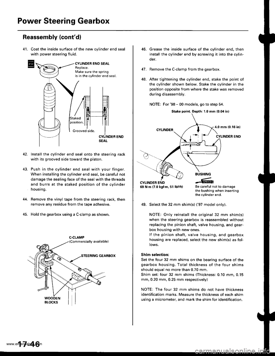
4l. Coat the inside surface of the new cvlinder end seal
with power steering fluid.
CYLINDEB ENO SEALReplace.Make sure the springis in the cylinder end seal.
43.
Stakedposrtron.
Grooved side.
42. Install the cylinder end seal onto the steering rack
with its grooved side toward the piston.
Push in the cylinder end seal with your finger.
When installing the cylinder end seal, be careful not
damage the sealing face of the seal with the threads
and burrs at the staked position of the cylinder
housing.
Remove the vinyl tape from the steering rack, then
remove any residue from the tape adhesive.
Hold the gearbox using a C-clamp as shown.
GEARBOX
44.
45.
C.CLAMP
17-46
46.Grease the inside surtace of the cylinder end, then
install the cylinder end by screwing it into the cylin-
der.
Remove the C-clamp from the gearbox.
After tightening the cylinder end, stake the point of
the cylinder shown below. Stake the cylinder in the
position opposite from where the stake was removed
during disassembly,
NOTE: For '98 - 00 models, go to step 54.
41.
48.
BUSHING
-tGCYLINDER END69 N.m (7.0 kgf.m,51 lbtft)8e careful not to damagethe bushing when insertingthe cylinder end.
49. Select the 32 mm shim(s) ('97 model onlv).
NOTE: Only reinstall the original 32 mm shim(s)
when the steering gearbox is reassembled without
replacing the pinion shaft. valve housing, and gear-
box housing with new ones.
lf the pinion shaft, valve housing, and gearbox
housing are replaced, select the new shim{s) as fol-
lows.
Shim selection:
Set the four 32 mm shims on the bearing surface of the
gearbox housing. Total thickness of the four shims
should equal no more than 0.70 mm.
Shim set: four 32 mm shims (Thickness: 0.10 mm, 0.15
mm, 0.20 mm, 0.25 mm respectively)
NOTE: The four 32 mm shims do not have thickness
identification marks. Measure the thickness of each shim
using a micrometer, and mark the shim for identification.
Stake point, Depth: 1,0 mm (0.04 inl
4.0 mm {0.16 in)
www.emanualpro.com
Page 907 of 1395
Knuckle/Hub Replacement
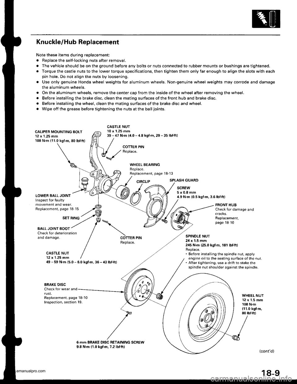
Note these items during replacement:
. Replace the selt-locking nuts after removal.
. The vehicle should be on the ground before any bolts or nuts connected to rubber mounts or bushings are tightened.
. Torque the castle nuts to the lower torque specifications, then tighten them only far enough to align the slots with each
pin hole. Do not align the nuts by loosening.
o Use only genuine Honda wheel weights for aluminum wheels. Non'genuine wheel weights may corrode and damage
the aluminum wheels.
. Onthealuminum wheels, remove the center cap from the inside of the wheel after removing the wheel.
. Before installing the brake disc, clean the mating surfaces of the front hub and brake disc.
. Before installing the wheel. clean the mating surfaces ofthe brake disc and wheel.
. Wipe off the grease before tightening the nuts at the balljoints.
CALIPER MOUNTING BOLT12 x 1.25 mm108 N.m (11.0 kgtm.80 lbt.ftl
LOWER BALL JOINTInspect for faultymovement and wear,Replacement, page'18 15
CASTLE NUT10 x 1.25 mm39 - 47 N.m (i1.0 - 4.8 kgf.m, 29 - 35 lbf.ftl
COTTER PINReplace.
WHEEL BEARINGBeplace.Replacement, page 18-13
CIRCLIPSPLASH GUARD
SCREW5x0.8mm4.9 N.m {0.5 kgf.m,3.6lbf.ft)
SET RING
FRONT HUBCheck for damage and
Replacement,page 18 10
BALL JOINT BOOTCheck for deteriorationano oamage.SPINOLE NUT24 x 1.5 mm245 N.m {25.0 kgI.m, 181 lbtft}Replace.. Before installing the spindle nut, applyengine oil to the seating surface of the nut.. After tightening, use a drift to stake thespindle nut shoulder against the spindle.
COTTER PINReplace.
CASTLE NUT12x 1.25 fim49 - 59 N.m 15.0 - 6.0 kgt.m. 36 - € lbf.ft)
BRAKE DISCCheck for wear andrust.Replacement, page 18-10Inspection, section 19.
WHEEL NUT12 x 1.5 mm108 N.m{11.0 kgt m,80 tbf.ftl
6 mm BRAKE DISC RETAINING SCREW9.8 N.m (1.0 kgtm, 7.2 lbtftl(cont'd )
18-9
www.emanualpro.com
Page 1003 of 1395
Doors
Front and Rear Door Glass
Adiustment (cont'dl
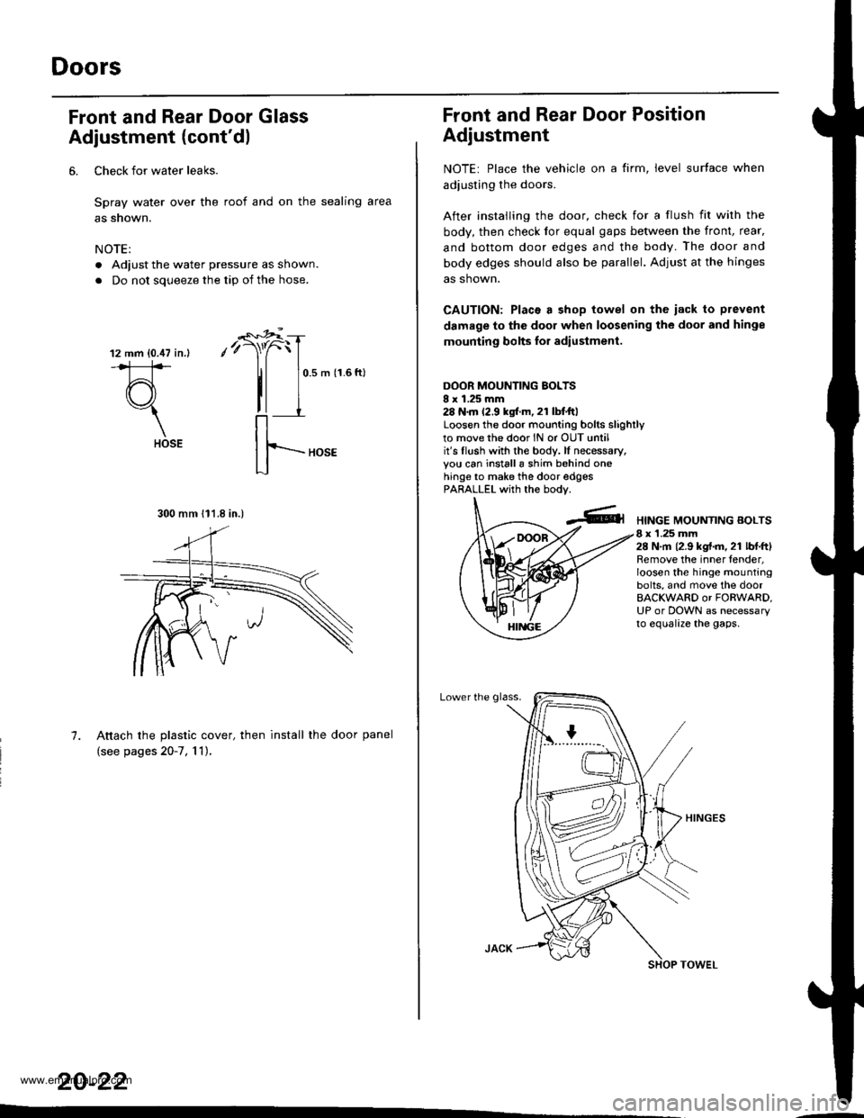
6. Check for water leaks.
Spray water over the roof and on the sealing area
as snown.
NOTE:
. Adjust the water pressure as shown.
. Do not soueeze the tio of the hose.
12 mm {0.47 in.l
#
(r\"1
HOSE
-"'*r"i
,'r)"f
tl
0.5 m (1.6 ftl
7. Attach the plastic cover, then install the door panel
(see pages 20-7, 'l 1),
20-22
..-
300 mm 111.8 in.)
Front and Rear Door Position
Adjustment
NOTE: Place the vehicle on a firm, level surface when
adiusting the doors.
After instailing the door, check for a flush fit with the
body, then check lor equal gaps between the front, rear.
and bottom door edges and the body. The door and
body edges should also be parallel. Adjust at the hinges
as shown.
CAUTION: Placa a shop towel on the iack to prevent
damage to the door when loosening the door and hinge
mounting bolts lor adiustment.
DOOR MOUNTING BOLTSI x 1.25 mm28 N.m 12.9 kgtr.m, 21 lbI.ftlLoosen the door mounting bolrs slighrlyto movethe door lN or OUT untilit's flush with the bodv. lf necessary,you can installa shim behind onehinge to make the door edgesPARALLEL with the bodv.
HINGE MOUNTING BOLTS8 x 1.25 mm28 N,m 12.9 kgt.m. 21 lbl.ftlRemove the inner fender,loosen the hinge mountingbolts, and move the doorBACKWARD or FORWARD,UP or DOWN as necessaryto equalize the gaps.
Lower the glass.
www.emanualpro.com
Page 1006 of 1395
Tailgate Door Striker Adjustment
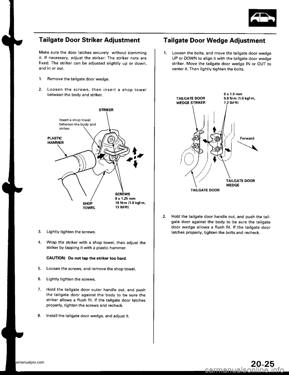
Make sure the door latches securely without slamming
it. lf necessary, adjust the striker: The striker nuts are
fixed. The striker can be adjusted slightly up or down,
and in or out.
1. Remove the tailgate door wedge.
2. Loosen the screws, then insert a shop towel
between the body and striker.
8 x 1.25 mm18 N.m (1.8 kgf.m,r 3 tbf.ft)
1.
4.
Lightly tighten the screws.
Wrap the striker with a shop towel, then adjust the
striker by tapping it with a plastic hammer.
CAUTION: Do not tap the striker too hard.
Loosen lhe screws, and remove the shop towel.
Lightly tighten the screws.
Hold the tailgate door outer handle out, and push
the tailgate door against the body to be sure thestriker allows a flush fit. lf the tailgate door latchesproperly, tighten the screws and recheck.
Install the tailgate door wedge, and adjust it.
STRIKER
Insen a shoptowelbetween the body and
Tailgate Door Wedge Adjustment
1. Loosen the bolts, and move the tailgate door wedge
UP or DOWN to align it with the tailgate door wedge
striker. Move the tailgate door wedge lN or OUT to
center it. Then lightly tighten the bolts.
TAILGATE OOOR
Hold the tailgate door handle out, and push the tail-gate door against the body to be sure the tailgate
door wedge allows a flush fit. lf the tailgate door
latches properly, tighten the bolts and recheck.
Forward
20-25
www.emanualpro.com
Page 1164 of 1395
Troubleshooting
Tips and Precautions (cont'dl
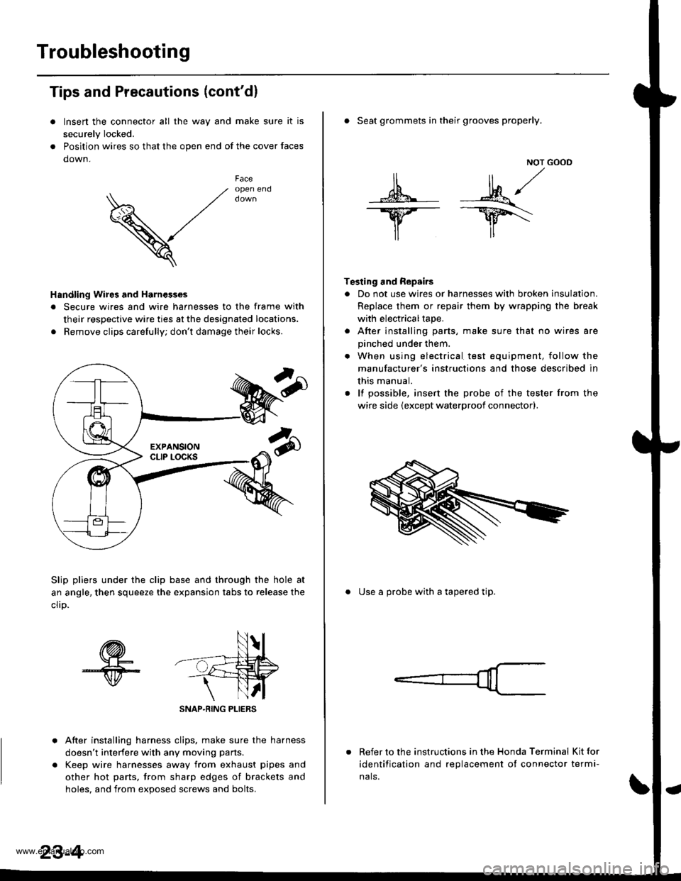
Insen the connector all the way and make sure it is
securely Iocked.
Position wires so that the open end of the cover faces
down.
V
Faceopen end
Handling Wires and Harnesges
. Secure wires and wire harnesses to the frame with
their respective wire ties at the designated locations.
. Remove clips carefully; don't damage their locks.
Slip pliers under the clip base and through the hole at
an angle, then squeeze the expansion tabs to release the
clrD.
After installing harness clips, make sure the harness
doesn't interfere with any moving pans.
Keep wire harnesses away from exhaust pipes and
other hot parts, trom sharp edges of brackets and
holes. and from exoos€d screws and bolts.
NOT GOOD
A -M/
lr lr*
T€sting and Repairs
. Do not use wires or harnesses with broken insulation.
Replace them or repair them by wrapping the break
with electricaltape.
. After installing parts, make sure that no wires are
pinched under them.
. When using electrical test equipment, follow the
manufacturer's instructions and those described in
this manual.
. lf possible, insert the probe of the tester from the
wire side (except waterproof connector).
. Seat grommets in their grooves properly.
. Use a probe with a tapered tip.
Refer to the instructions in the Honda Terminal Kit for
identification and replacement of connector termi-
nals.
www.emanualpro.com
Page 1314 of 1395
Description
J)
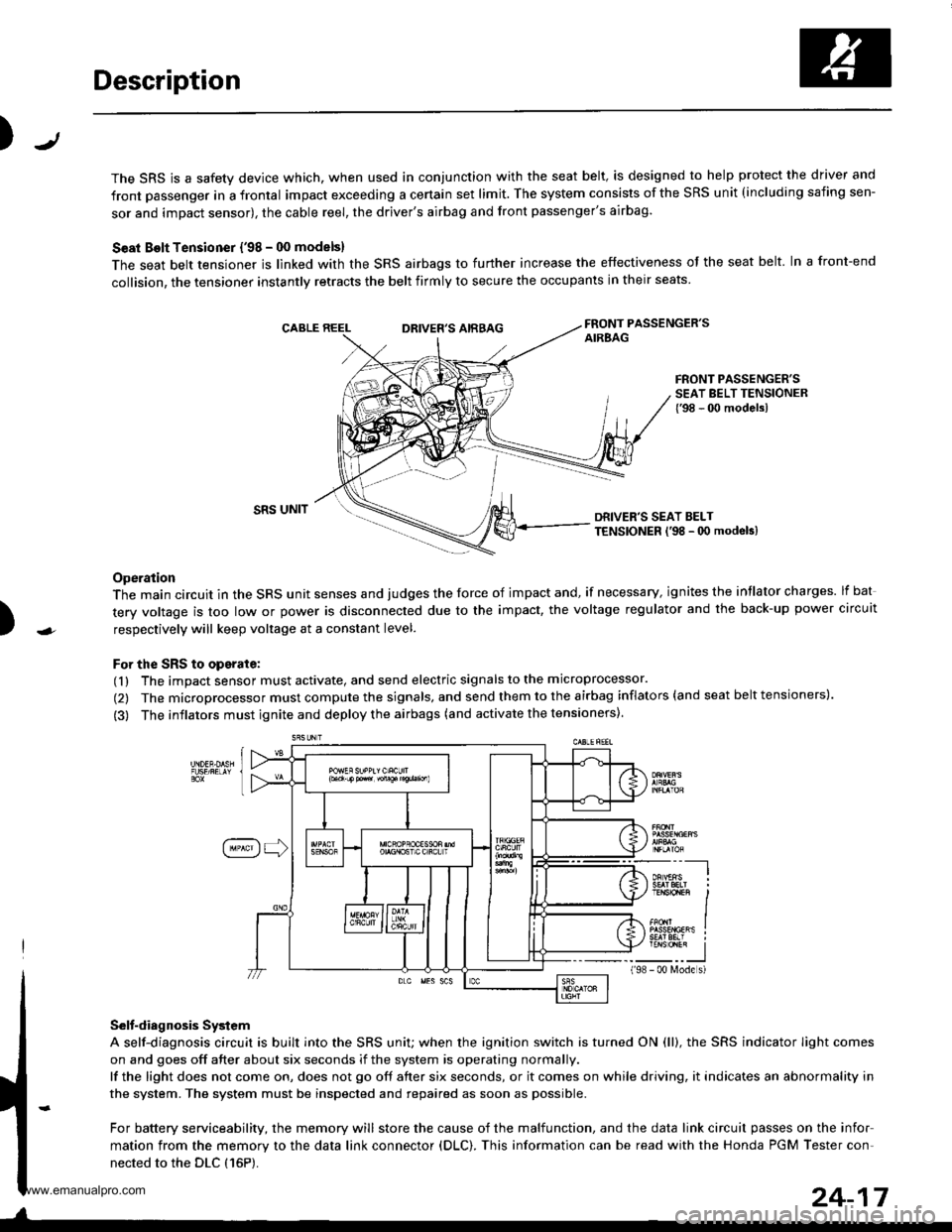
The SRS is a safety device which, when used in conjunction with the seat belt, is designed to help protect the driver and
front passenger in a frontal impact exceeding a certain set limit. The system consists of the SRS unit (including safing sen-
sor and impact sensor), the cable reel, the driver's airbag and front passenger's airbag.
Seat Bolt Tensioner {'98 - 00 models}
The seat belt tensioner is linked with the SRS airbags to further increase the effectiveness of the seat belt. In a front-end
collision, the tensioner instantly retracts the belt firmly to secure the occupants in their seats
FRONT PASSENGER'SAIREAGDRIVER'S AIRBAG
FRONT PASSENGER'SSEAT BELT TENSIONER{'98 - 00 modelsl
)
SRS UNITDRIVER'S SEAT BELTTENSIONER l'98 - 0O modeb)
Operation
The main circuit in the SRS unit senses and judges the force of impact and, if necessary, ignites the intlator charges. lf bat
tery voltage is too low or power is disconnected due to the impact, the voltage regulator and the back-up power circuit
respectively will keep voltage at a constant level.
For the SRS to operate:
(1) The impact sensor must activate, and send electric signals to the microprocessor.
(2) The microprocessor must compute the signals, and send them to the airbag inflators (and seat belt tensioners).
(3) The inflators must ignite and deploy the airbags (and activate the tensioners).
Selt-diagnosis System
A self-diagnosis circuit is built into the SRS uniU when the ignition switch is turned ON (ll), the SRS indicator Iight comes
on and goes off after about six seconds if the system is operating normally.
lf the light does not come on, does not go off after six seconds, or it comes on while driving, it indicates an abnormality in
the system. The system must be inspected and repaired as soon as possible.
For battery serviceability, the memory will store the cause of the malfunction, and the data link circuit passes on the infor
mation from the memory to the data link connector (DLC). This information can be read with the Honda PGM Tester con-
nected to the DLC {16P).
198
---__-l
TENSTO1En II
_-___J- 00 N4ode s)
24-17
www.emanualpro.com