Page 1084 of 1395
Wiper Arms and Washer Nozzles Adiustmenl
Wind3hield Wipor/Washer:
1, Adiust the wiper arms so that their park positions
match the illustration.
Viow from flont io roar
GLASS
2. Insert a tack into the washer nozzles. and
them so that they aim at positions A, A', B,
shown in the illustration.
adjust
and B'
Distance
^,J;-ll\
from center
line
from black
ceramic edge
A and A'3,$ mm (13.5 in.)287 mm (11.3 in.)
B and B'122 mm (4.80 in.)352 mm (13.9 in.)
Rear Window wipor/Washer:
Vi6w trom roar to lront
REARsPo[.-ER
C.nlar linoL
Align to the rear windowdefogger grid line.
Distance
ru"rrr. "i.
'_\from center
ltne
from black
ceramic edge
27 mm (1.1 in.)88 mm (3.5 in.)
20-103
www.emanualpro.com
Page 1089 of 1395
POlNTx.y / I
'sad
POINT m3, m4
Upper Arm
M12 x P1.25
Locate Hole
POINT 3, s1
o14 {0.551 For Trailing Aim
POINT v
Fuel Tank Strap Poinr
2700.5 (106.32)SECTION BBRear Damoer Center
POINT n
FOINT
rg (0.3) Fuel TStrap Center
271,1(10,6.9)
o2010.8| Locate Hole
For Rear Cros3 Beam
For Reer Cross Beam
POINT w
Bear Damper LowerBushing Point
I
\-
ql
ol
.df
20-109
www.emanualpro.com
Page 1094 of 1395
Component Location
lndex (cont'dl
SRS components are located in this area. Review the SRS component locations, precautions, and procedures in the SRS
section (24) before performing repairs or service.
BLOWER UNITReplacement, page 22-46Ovethaul, page 22 47
/alowen ruoronl
\Test, page 22-16 /
EVAPORATORFeplacement, page 22-48Overhaul, page 22,49
RECIRCULATIONCONTROL MOTORReplacement, page 22 42
HEATER UNITReplacement, page 22 50Overhaul, page 22 52
lest, pag.e 22 42
A/C FILIERReplacement. page 22-50VALVE CABLEAdjustment, page 22-53
RECIRCULATIONCONTROL SWITCH
a/c swtTcH
MODEMOTOR
REAR WINDOWDEFOGGERSwlTCHSee section 23Replacement, page 22-41Test, page 22-41MODE CONTROLDIAL
HEATER CONTROLPANELReplacement, page 22 46
swtTcH
22-4
CONTROL
www.emanualpro.com
Page 1099 of 1395
cnNj@_snN
GRY
PNK/BLK
NED/8LU
REO/YEL
YEL/BLU
8RN/WHT
GRNI/VHT
GRN/RED
POWERTRANSISTOR
c401c402
22-9
4
ORNMHT
Fg"{
EVAPONATORTEMPERATURE SENSOR
fi3'.Hfi|$l#i9D>
"'"-
DASH LTGHTS _/4EE|GHTNESS < l_ REDCONTROLLER -!
REAR
fllf$!S,* (l aLurrLRELAY
O:8P coNNEcToR
n :20P c0NN€CToR
YEL/RED
GRN/YEL
8LU/8LK
BRN
YEL
s5v s coM
AMD P AIR MIXCONTROLMOTOB
HOT
VENT
B/LI/lODEH CONT8OLl
10T0RH/D MDEF
HEATER CONTROL PANEI-
8LK
www.emanualpro.com
Page 1130 of 1395

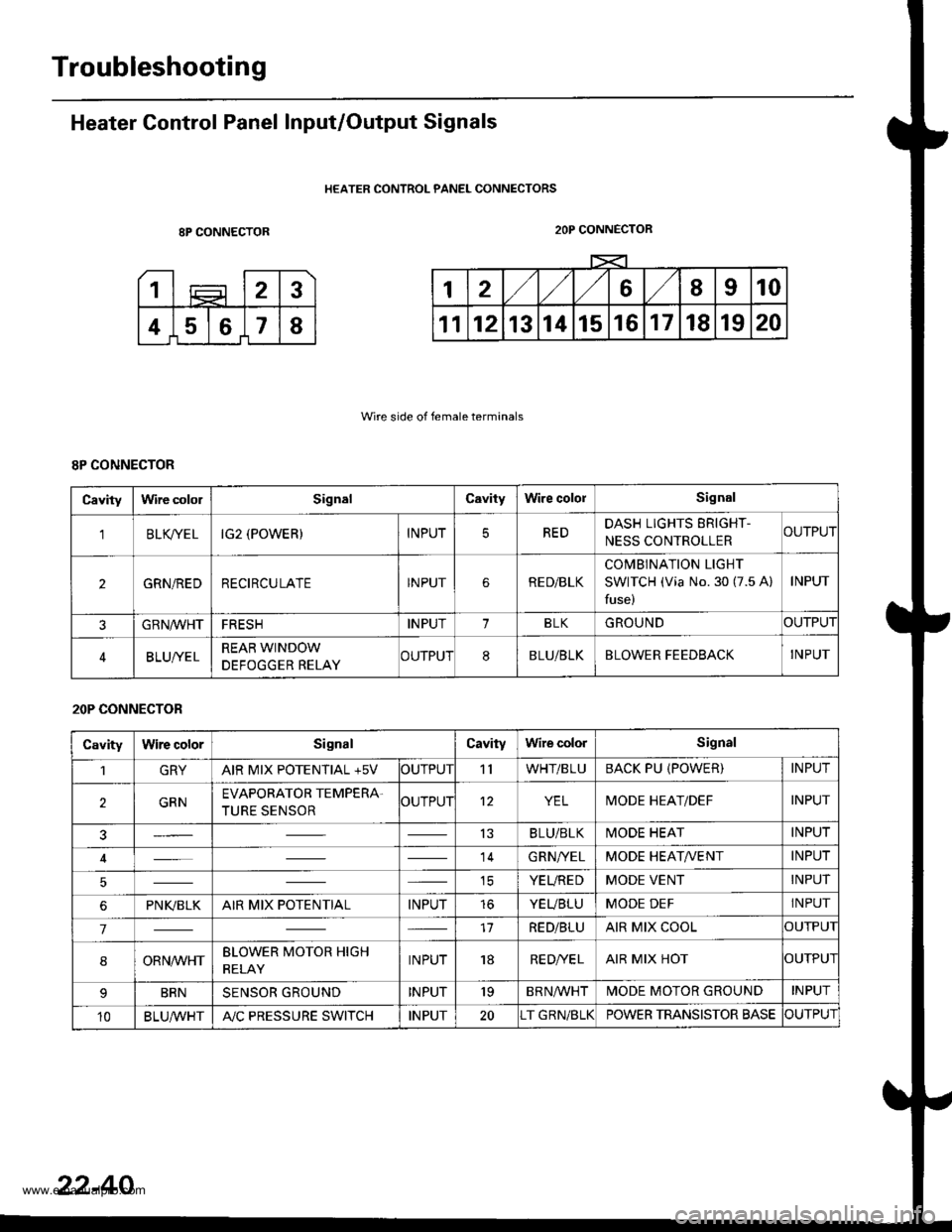
Troubleshooting
Heater Control Panel Input/Output Signals
HEATER CONTROL PANEL CONNECTORS
8P CONNECTOR
Wire side of female terminals
2OP CONNECTOR
8P CONNECTOR
Cavitylrvire cololSignalCavityWire cololSignal
'lBLK/TE LIG2 (POWER)INPUTREDDASH LIGHTS ERIGHT-
NESS CONTROLLERCUTPUT
2GRN/REDRECIRCULATEINPUTRE D/BLK
COMBINATION LIGHT
SWITCH (Via No. 30 (7.5 A)
fuse)
INPUT
GRN/VVHTFRESHINPUT1BLKGROUNDOUTPUT
BLUI/ELREAR WINDOW
DEFOGGER RELAYCUTPUT8BLU/BLKBLOWER FEEDBACKINPUT
20P CONNECTOR
CavityWire colorSignalCavityWire colorSignal
1GRYAIR MIX POTENTIAL +5VOUTPUT'llWHT/BLUBACK PU (POWER)INPUT
2GRNEVAPORATOR TEMPERA.
TURE SENSOROUTPUT12YELMODE HEAT/DEFINPUT
13BLU/BLKMODE HEATINPUT
14GRN/YELMODE HEAT/VENTINPUT
ICYEUREDMODE VENTINPUT
6PNI(BLKAIR MIX POTENTIALINPUTtoYEUBLUMODE DEFINPUT
717RED/BLUAIR MIX COOLOUTPUI
8ORNrur'HTBLOWER MOTOR HIGH
RELAYINPUT18RE D/VE LAIR MIX HOTOUTPUI
BRNSENSOR GROUNDINPUT'19BRNA/VHTIVIODE MOTOR GROUNDINPUT
10BLU,ryVHTA"/C PRESSURE SWITCHINPUT20T GRN/BLKPOWER TRANSISTOR BASECUTPUT
22-40
www.emanualpro.com
Page 1168 of 1395
Relay and Gontrol Unit Locations
Dashboard (cont'd)
HEATER CONTROL PANEL
REAR WINDOW DEFOGGER RELAY
WINDOW RELAY
-rj,r1 /-\,r1Iu lJ-JlJ r*t
23-8
INTEGRATEO CONTROL UNITTURN SIGNAL/HAZARD RELAY
www.emanualpro.com
Page 1170 of 1395
Relay and Control Unit Locations
Dashboard (cont'd) and Door
REAR ACCESSORY SOCKET RELAYI Wire colors: YEL/GRN, JIWHT/BLK. BLK, .nd YEL/BLU l
REVERSE RELAY {A/TII Wire colonr YEI-/RED, IIYEL/RED, YEL, .nd GRN/BLK IREAR WINDOW WIPERCONTROL UNIT 137 mod.ll
KEYIISS/POWER DOOR L(rcKCONTROL UNIT
INTERLOCX CONTROL UNIT
23-10
www.emanualpro.com
Page 1171 of 1395

Gonnector ldentification and Wire Harness Routing
How to ldentity Connectors:
ldentification numbers have been assigned to all connectors, The number is preceded by the letter "C" for connectors.
"G" for ground terminals or "T" for non-ground terminals.
Location
HarnessEngine CompartmsntDashboardOthers lFloor, Door,
8oof, Tailgate)
Starter cableT1, T2 and @
Battery ground cableG1 and O
Engine ground cableT3
Transmission ground cableT4
G3
Engine wire harnessC101 through C137
T101 and T102
G101
Engine compartment ware harnessC201 through C218
G201 and G202
Under-hood ABS fuse/relay box
wire harness
t5ano9
Main wire harnessC301 through C309
C351 through C361
C401 through C447
G401 and G402
Dashboard wire harnessC501 through C524 (C525)
G501
Left side wire harnessC551 through C581
G551, G552 and G553
Right side wire harnessC601 through C605
lnterior wire harnessC701 through C703
Rear bumper wire harnessC641 through C643
Heater sub-harnessC731 through C740
Secondary heated oxygen sensor
sub-harness
C721 through C722
Combination switch sub-harnessC751 through C760
Driver's door wire harnessC661 through C667
Front passenger's door wire harnessC6Tl through C676
Left rear door wire harnessC681 through C684
Right rear door wire harnessC69'l through C694
Rear wire harnessC611 through C520
Tailgate wire harnessC631 through C634
G631
SRS main harnessC801 through C808
G801
High mount brake light sub-harnessC651 through C653
Fuel tank oressure sensor sub-harnessC645 through C647
www.emanualpro.com