1998 HONDA CR-V main
[x] Cancel search: mainPage 948 of 1395

Anti-lock Brake System (ABSI,'97 - 00 Models
Special Tools ............. 19-26
Component Locations ......................... 19-27
Anti-lock Brake System (ABS)
Features/Construction ............. ......, 19-2A
Circuit Diagram ......... 19-32
ABS Control Unit Terminal
Arrangement ......... 19-34
Troubleshooting Precautions ............. 19-36
Diagnostic Trouble Gode (DTC)
Diagnostic Trouble Code (DTC)
Indication (SCS Model ................ 19-38
DTG Erasure (MES Mode) ............... 19-39
Troubleshooting lndex .................... 19-40
Troubleshooting
ABS Indicator Light Does Not
Come On ............ 19-41
ABS Indicator Light Does Not
Go Off (No DTC) ........................... 19-43
DTC 1r - 18:
Wheel Sensor .... 19-45
DTC 31 - 38:
Solenoid ............. 19-47
DTC 51 - 53:
ABS Pump Motor ......................... 19-49
DTC 54:
Main Relay ......... 19-52
DTC 61:
lgnition Voltage ........................... 19-54
DTC 81:
Central Processing Unit (CPU) .... 19-55
Modulator Unit
Removal/lnstallation ....................... 19-56
ABS Control Unit
Replacement ..,...... 19-57
Pulsers/Wheel Sensors
Inspection .............. 19-57
Wheel Sensor Replacement ............ 19-58
www.emanualpro.com
Page 952 of 1395

ABS Control
The ABS control unit detects the wheel speed based on the wheel sensor signal it received, then it calculates the vehicle
speed based on the detected wheel speed. The control unit detects the vehicle speed during deceleration based on the
rate of deceleration.
The ABS control unit calculates the slip rate of each wheel, and it transmits the control signal to the modulator unit
solenoid valve when the slip rate is high
The pressure reduction control has three modes: pressure reducing, pressure retaining, and pressure intensi{ying modes.
Self-diagnosis Function
The ABS control unit is equipped with a main cPU and a sub cPU, that check each other for problems.
The CPUs check the circuit of the system.
When the CPUS detect failure, they shift to the "system down mode" or the "control inhibition mode".
The self-diagnosis can be classitied into these four categories:
O: Initial diagnosis
O: Except ABS control
O; During ABS control
@: During warning
On-board Diagnosis Function
The ABS system can be diagnosed with the Honda PGM Tester.
The ALB Checker cannot be used with this system. For air bleeding. and checking wheel sensor signals, use the Honda
PGIM Tester. See the Honda PGM Tester user's manuals for specific operating instructions.
(cont'd)
19-29
ABS CONTROL I-INIT
MODEABSINDICATOR LIGHTMAIN
RE LAY
SOLENOID
VALVERestan conditionDTC
SYSTEM
DOWNONNo
operatron
Drive
inhibitionOperation*rlgnition
switchOFF - oN (ll)Memory
CONTROL
INHIBITIONONNo
operaton
Drive
inhibitionOperationAutomaticlVemory
*1: Except CPU failure
www.emanualpro.com
Page 959 of 1395

Troubleshooting Precautions
ABS lndicalor
1 lf the system is oK, the ABS indicator goes off two seconds after turning the ignition switch oN 1l) wathout staningthe engine, and then comes on again and goes off after two seconds. This occurs because the ABS control unit isturned on by the lG2 power source.2. The ABS indicator comes on when the ABS control unit detects a problem in the system. However, even thouoh thesystem is operating properly, the ABs indicator will come on too, under the following conditions:. Signal disturbance
. Wheel spin
. Only drive wheels rotate. Battery voltage fluctuates
To determine the actual cause of the problem, question the customer about the problem, taking these conditions intoconsideration:
3 When a problem is detected and the ABS indicator comes on, the indicator can stay on until the ignition switch isturned OFF, or it can automatically go off, depending on the mode.. Indicator stays on untilthe ignition switch is turned off: When the system is in the system down mode.. Indicator automatically goes off: When the system is in the control inhibition mode.4 The ABS indicator stays on when the system is reactivated without erasing the DTC, but it goes off after starting thevehicle.
When the wheel sensor system is faulty and the ABS indicator comes on. the algorithm of the system automatically turnsoff the ABS indicator after the wheel speed signal returns to the normal speed. Also, when the DTc is erased, the cpu isreset and the ABS indicator goes off when the system checked out normal by the initial diagnosis.Therefore, test-drive the vehicle after servicing the wheel sensor system. and be sure that the ABS indicator does notcome on.
5 When the ABS control unit outputs battery voltage to the gauge assembly, the ABS indicator ooes off.
Diagnostic Trouble Code (DTCI
1. The diagnostic trouble code (DTc) is memorized when a problem is detected and the ABS indicator does not go off,or when the ABS indicator comes on.The DTc is not memorized when the ABS indicator comes on unress the cpu is activated,2 The memory can hold any number of DTCs. However, when the same DTc is detected twice or more, the tater one iswritten over the old one.
Therefore, when the same problem is detected repeatedly, it is recorded as one DTC.3. The DTCs are indicated in the order of ascending number, not in the order they occur.4. The DTCS are memorized in the EEPROM (non-volatile memorv).Therefore, the memorized DTcs cannot be canceled by disconnecting the battery. perform the specified procedures toerase the DTCS.
Self-diagnosis
1. Self-diagnosis can be classified into these four categories:' Initial diagnosis: Performed right after the eng ine starts and untir theABS indicator goes off.. Except ABS control: Performed when the ABS is not functioning.. During ABS control: Performed when the ABS is functioning.. During warning: Performed when the ABS indicator is ON.2. The system performs the fo|owing contrors when a probrem is detected by the serf-diagnosis:. ABS indicator ON. Memorv of DTC. Mode changetothe "system down mode,, or the ,,control inhibition mode,,.
MODEABS INDICATORMAIN
RELAY
SOLENOID
VALVECPURestart conditionDTC
SYSTEM
DOWNONNo
operation
Drive
inhibitionOperation*rlgnition
switchoFF - ON l)Memory
CONTROL
INHIBITIONONNo
operal|on
Drive
inhibitionOperationAutomaticlMemory
*1: Except CPU failure
19-36
www.emanualpro.com
Page 961 of 1395

Diagnostic Trouble Code (DTC)
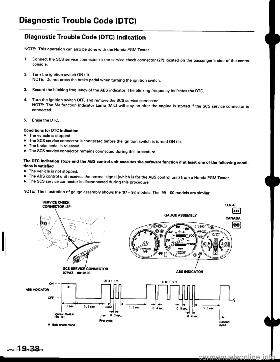
Diagnostic Trouble Gode IDTCI Indication
NOTE: This operation can also be done with the Honda pGM Tester.
1. Connect the SCS service connector to the service check connector (2P) located on the passenger's side of the centerconsote.
2. Turn the ignition switch ON (ll).
NOTE; Do not press the brake pedal whenturningthe ignition switch.
3 Record the blinking frequency of the ABS indicator. The brinking frequency indicates the DTc.
4. Turn the ignition switch OFF. and remove the SCS service connector.NOTE: The Malfunction Indicator Lamp (MlL) will stay on after the engine is startsd if the SCS seryica connecror rsconnected.
5. Erase the DTC.
Conditions for DTC indication. The vehicle is stopped.. The SCS service connector is connected before the ignition switch is turned ON flt).. The brake pedal is released.. The SCS service connector remains connected during this procedure.
The DTC indication stops and the ABS control unit axecutos tha softwaro lunction if at least one of tho following condi-tions i3 satisfiod:
. The vehicle is not stoooed.. The ABS control unit receives the normal signal (which is for the ABS control unit) from a Honda pGM Tesrer.. The SCS service connector is disconnectod during this procedure.
NQTE: The illustration of gauge assembly shows the '97 - 98 models. The '99 - oo models are similar.
SEFVICE CHECKCONNESTOR I2P}
GAUGE ASSEMBLY
A8S II{DEATOR
u.s.A.
@
CANADA
@
19-38
www.emanualpro.com
Page 962 of 1395

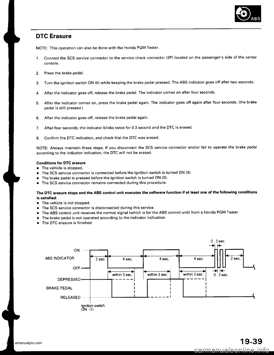
DTC Erasure
NOTE: This operation can also be done with the Honda PGM Tester.
1. Connect the SCS service connector to the service check connector (2P) located on the passenger's side of the center
console.
2. Press the brake oedal.
3. Turn the ignition switch ON (ll) while keeping the brake pedal pressed. The ABS indicator goes off after two seconds.
4. After the indicator goes off, release the brake pedal. The indicator comes on after four seconds.
5. After the indicator comes on, press the brake pedal again. The indicator goes off again after four seconds (the brake
oedal is still Dressed.)
6. After the indicator goes off, release the brake pedal again.
7. After four seconds. the indicator blinks twice for 0.3 second and the DTC is erased.
8. Confirm the DTC indication, and check that the DTC was erased.
NOTE: Always maintain these steps. lf you disconnect the SCS service connector and/or fail to operate the brake pedal
according to the indicator indication, the DTC will not be erased.
Conditions for DTC erasure
. The vehicle is stopped.
. The SCS service connector is connected before the ignition switch is turned ON (ll)
. The brake pedal is pressed before the ignition switch is turned ON (ll).
. The SCS service connector remains connected during this procedure.
The DTC erasure stops and the ABS control unit executes the software funqtion it at least one of the following conditions
b satisfied:
. The vehicle is not stopped.
. The SCS service connector is disconnected during this service.
. TheABScontrol unit receives the normal signal (which is for the ABS control unit) from a Honda PGM Tester.
. The brake pedal is not operated according to the indicator indication
. The DTC erasure is finished.
ON
ABS INDICATOR
OFF
DEPRESSED
BRAKE PEDAL
within 3 sec.0.3sec.
0.3sec.
within 3s€c. I within 3 s€c.
lonition switchdN (r)
RELEASED
19-39
www.emanualpro.com
Page 963 of 1395

Diagnostic Trouble Code (DTC)
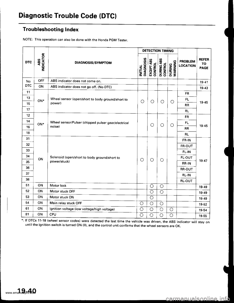
Troubleshooting Index
This operation can also be done with the Honda pGM Teste..
*: lf DTcs 11-18 {wheel sensor codes) were detected the last time the vehicle was driven, the ABs indicator wi
stav onuntil the ignition switch is turned ON (ll), and the control unit confirms that the wheel sensors are OK,
19-40
DTC3R
DETECTION TIMING
PROBLEM
LOCATION
REFER
TO
PAGE
Io
<=EXzd
8
93gl (J
4,,to
B8
2=
ET63
No
DTC
OFFABS indicator does not come on.19,4'l
ONABS indicator does not go off. (No DTC)19-43't1
oN*Wheel sensor {open/short to body ground/short topower)oooo
FR
19-45
13FL't5RR
17RL
12
oN*Wheel sensor/Pulser (chipped pulser gearlelectrical
notse,ooo
FR
19-45
't4FL
RR
18RL
31
ONSolenoid (open/short to body ground/short topower/stuck)ooo
FR-IN
19-47
32FR-OUT
FL.IN
34FL-OUT
RB-IN
36RR-OUT
37RL-IN
38RL.OUT
ONMotor lockoo19-49
ONMotor stuck OFFoo19-49
53ONMotor stuck ONo19-49
54ONMain relay stuck OFFoooia_at
6lONlgnition voltage (low voltage/high voltage)oooo'19-54
81ONoooo19-55
www.emanualpro.com
Page 975 of 1395
![HONDA CR-V 1998 RD1-RD3 / 1.G Workshop Manual
Troubleshooting
DTG 54: Main Relay
IWHT/GRNI
AAS CONTROL UNIT 26P CONNECTON
Wire side of female terminals
ABS COf{TROL UN]T 22P CONNECTOR
PCOMIGRN/WHTIscoM{BLK/WHTI
Wire side of female terminals
- Wi HONDA CR-V 1998 RD1-RD3 / 1.G Workshop Manual
Troubleshooting
DTG 54: Main Relay
IWHT/GRNI
AAS CONTROL UNIT 26P CONNECTON
Wire side of female terminals
ABS COf{TROL UN]T 22P CONNECTOR
PCOMIGRN/WHTIscoM{BLK/WHTI
Wire side of female terminals
- Wi](/manual-img/13/5778/w960_5778-974.png)
Troubleshooting
DTG 54: Main Relay
IWHT/GRNI
AAS CONTROL UNIT 26P CONNECTON
Wire side of female terminals
ABS COf{TROL UN]T 22P CONNECTOR
PCOMIGRN/WHTIscoM{BLK/WHTI
Wire side of female terminals
- With the ignition switch ON(lll, the ABS indicator doesnot go off.- With the SCS service connec-tor connected {see page 19-381,DTC 54 is indicatod.
Check the ABS +B 120 A) fuse inthe under-hood ABS luse/relaybox, and reinstall the fuse if it isoK.
FeDlace the tu3e and recheck.
Ch€ck tor an open in the 81, 82circuit:Measure the voltage betweenbody ground and the ABS controlunit 26P connector terminal No. 14and No. 15 individually.
Repair open in the wiro bstweonth6 ABS conirol unit and theunder-hood ABS fuse/rolay box,
ls there battery voltage?
Check for a short to body groundin the PMR circuit:L Turn the ignition switch OFF.2. Remove the pump motor relay.3. Disconnect the ABS controlunit 22P connector.4. Check lor continuity betweenterminal No. 19 and bodygrouno.
Repair short to body ground inthe wire betweon the under-hood ABS lGe/r.lay box and theABS control unit.
Check for a short to body groundin the PCOM, SCOM cilcuit:1. Disconnect the ABS controlunit 26P connector.2. Check tor continuity betweenbody ground and the ABS con-trol unit 26P terminals No- 1and No.2 individually.
. R€pair short to body ground inth€ P1COM circuit wire betweenthe ABS control unit and theund6r-hood ABS tuse/r6layoox.. R6p.ir short to body ground inthe PCOM or SCOM circuit wirebetweon th6 ABS control unitand lhe mod!lator unit.. R.Dlece tho modulrtor unit.(Short circuit inside the unitl
ls there continuity?
(To page 19-53)
www.emanualpro.com
Page 1015 of 1395

Glass
Windshield Replacement (cont'dl
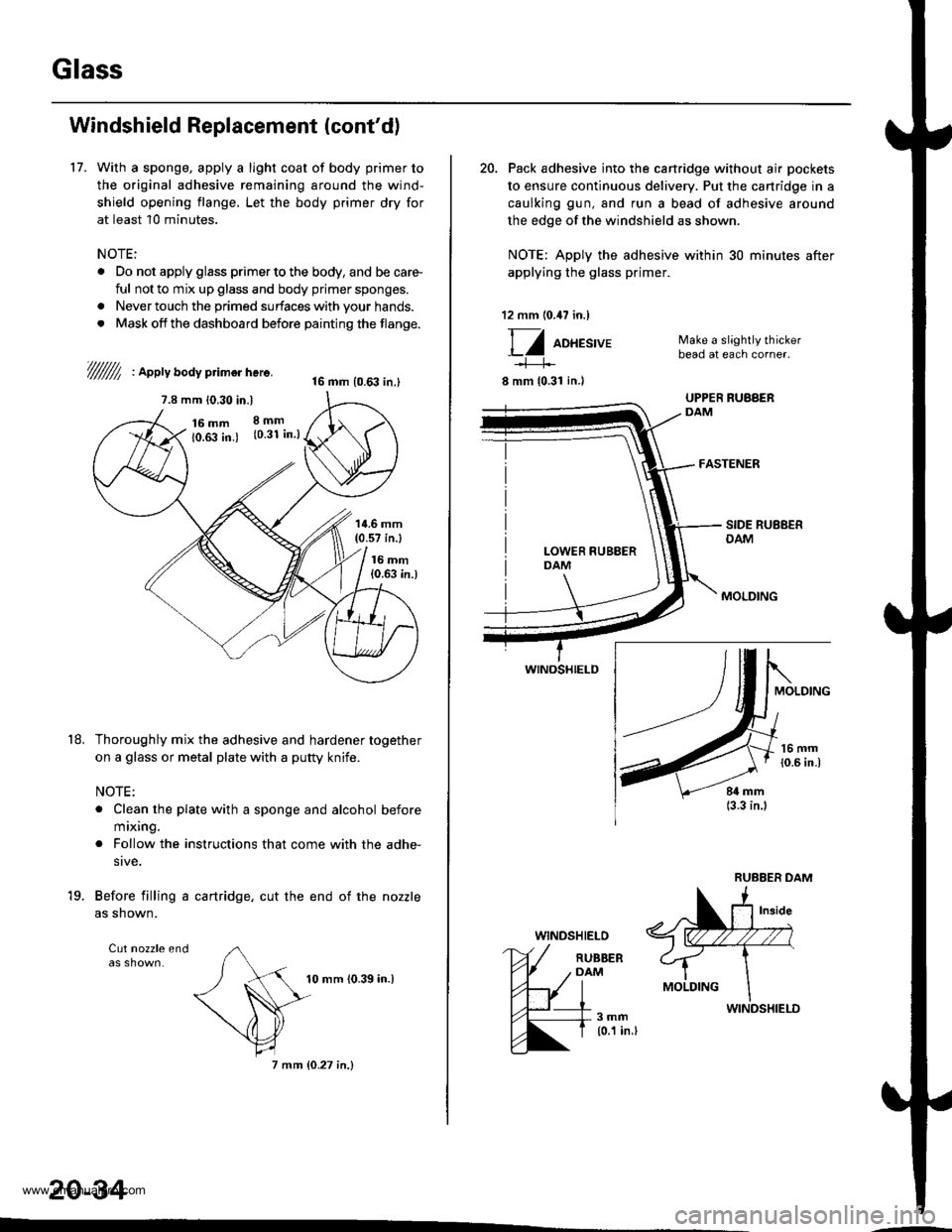
17. With a sponge, apply a light coat of body primer to
the original adhesive remaining around the wind-
shield opening flange, Let the body primer dry for
at least 10 minutes.
NOTE:
. Do not apply glass primer to the body, and be care-
ful not to mix up glass and body prjmer sponges.
. Never touch the primed surfaces with your hands.
. Mask off the dashboard before painting the flange.
///////l , apptv aoav primor here.16 mm {0.63 in.l
7.8 mm 10.30 in.)
16 mm10.fi in.)
8mm(0.31 in.)
't8,
14.6 mm(0.57 in.l
16 mm{0.63 in.)
Thoroughly mix the adhesive and hardener together
on a glass or metal plate with a putty knife.
NOTE:
. Clean the plate with a sponge and alcohol before
mixing.
. Follow the instructions that come with the adhe-
sive.
Before filling a cartridge, cut the end of the nozzle
as shown.
Cut nozzle end
'19.
10 mm {0.39 in.)
7 mm {0.27 in,}
20-34
20, Pack adhesive into the cartridge without air pockets
to ensure continuous delivery. Put the cartridge in a
caulking gun, and run a bead of adhesive around
the edge of the windshield as shown.
NOTE: Apply the adhesive within 30 minutes after
applying the glass primer.
12 mm (0.47 in.)
Ff oo*tt'u'
8 mm {0.31 in.l
WINOSHIELD
WINDSHIELO
Make a slightly thickerbead at each corner.
FASTENER
RUBBERDAM
3mm{0.1 in.l
www.emanualpro.com