1998 HONDA CR-V Sensors
[x] Cancel search: SensorsPage 519 of 1395

Description
General Operation
The Automatic transmission is a 3-element torque converter and triple-shaft electronically controlled unit which provides 4
speeds forward and 1 reverse speed The unit is positioned in line with the engine'
There are two tvoes of automatic transmission on CR-V; the four-wheel drive (4WD) model ('97 - 00)' and the front-wheel
drive (2WD) model ('98 - 00).
Toroue Converter, G€ars, and Clutches
The torque converter consists of a pump. turbine. and stator assembly in a single unit. The torque converter is connected to
the engine crankshatt. These parts turn together as a unit as the engine turns. Around the outside of the torque converter is
a ring gear which meshes with the starter pinion when the engine is started. The torque converter assembly serves as a fly-
wheel while transmitting power to the transmission mainshaft.
The transmission has three parallel shafts: the mainshaft. the countershaft, and the sub-shaft. The mainshaft is in line with
the engine crankshaft. The mainshaft includes the 1st, 2nd. and 4th clutches, and gears lor 3rd,2nd,4th. reverse and 1st
(3rd gear is integral with the mainshaft, while reverse gear is integral with the 4th gear). The countershaft includes the 3rd
clutch and gears for 3rd,2nd, 4th, reverse, 1st, and park. Reverse and 4th gears can be locked to the countershaft at its cen-
ter, providing 4th gear or reverse, depending on which way the selector is moved. The sub-shaft includes the lst-hold
clutch and gears for lst and 4th.
The gears on the mainshaft are in constant mesh with those on the countershaft and sub-shaft. When certain combinations
of gears are engaged by the ctutches, power is transmitted from the mainshaft to the countershaft to provide E, D!, tr, tr,
and E position ('97 - 98 models). and E. E, E, and E position ('99 - 00 models)'
Electlonic Control
The electronic controt system consists of the Powenrain Control Module (PCM), sensors, a linear solenoid, and four
solenoid valves. Shifting and lock-up are electronically controlled for comfortable driving under all conditions. The PCM is
located below the dashboard, under the kick panel on the passenger's side.
Hydraulic Control
The valve bodies include the main valve body, the secondary valve body, the regulator valve body, the servo body, and
the lock up valve body. They are bolted to the torque converter housing. The main valve body contains the manual valve,
the 1-2 shift valve, the 2nd orifice control valve. the CPB {Clutch Pressure Back-up) valve, the modulator valve, the servo
control valve. the relief valve, and ATF pump gears. The secondary valve body contains the 2-3 shift valve, the 3-4 shift
valve, the 3,4 orifice control valve. the 4th exhaust valve and the CPC (Clutch Pressure Control) valve. The regulator valve
bodv contains the pressure regulator valve, the torque converter check valve, the cooler relief valve, and the lock-up con-
trol valve. The servo body contains the servo valve which is integrated with the reverse shift tork, and the accumulators
The lock-up valve body contains the lock-up shift valve and the lock-up timing valve. The linear solenoid and the shift con-
trol solenoid valve Ay'B are bolted to the outside of the transmission housing, and the lock-up control solenoid valve Ay'B is
bolted to the outside of the torque converter housing. Fluid trom the regulator passes through the manual valve to the
various control valves. The clutches receive fluid from their respective feed pipes or internal hydraulic circuit
ShiftControl Mechanism
input from various sensors located throughout the vehicle determines which shift control solenoid valve the PCM will acti-
vate. Activating a shift control solenoid valve changes modulator pressure, causing a shift valve to move. This pressurizes
a line to one of the clutches. engaging that clutch and its corresponding gear. The shift control solenoid valves A and B are
controlled by the PCM.
Lock-up Mechanism
tn E! position (,97 - 98 modets) and in E position ('99 - O0 models), in 3rd and 4th, and in Del position in 3rd ('97 - 98
models) and in El position with Over,Drive (O/D) is OFF (by pressing rhe O/D switchl in 3rd ('99 - 00 models), pressurized
fluid is drained from the back of the torque converter through a fluid passage, causing the lock-up piston to be held
against the torque converter cover, As this takes place, the mainshaft rotates at the same speed as the engine crankshaft.
Together with hydraulic control, the PcM optimizes the timing of the lock-up mechanism The lock-up valves control the
range of lock-up according to lock-up control solenoid valves A and B, and the linear solenoid. When lock-up control
solenoid valves A and B activate, the modulator pressure changes. The lock-up control solenoid valves A and B and the
linear solenoid are controlled by the PCM.
{cont'd)
14-3
www.emanualpro.com
Page 531 of 1395

Electronic Control System
The electronic control svstem consists of a Powertrain Control Module (PCM), sensors, a linear solenoid, and four solenoid
valves. Shifting and lock-up are electronically controlled for comfortable driving under all conditions. The PCM is located
below the dashboard, under the kick panel on the passenger's side.
'97 - 98 Mod€ls
PGM.FIControl Sy3t6m
Throttl€ Poshion SensorSignalVehicle Sp.ed SensorSignal
Engino Coolant TamperetureService Check connectorSonsor Signrl
A/T Control Sy3tem
INTERLOCK
Shift Cont.ol
Shift ControlSolenoid valve ACONTROL UNITr
RShift ControlSolenoid Valve B
N
Linear SolenoidDr
Lock-up Control
Ds
Lock-up ControlSolenoid Valve A2
Lock-up ConirolSol6noid valvo B1
M.inshaft Spoed SensorSignel-D! Indicator Light
Count€rahaft Speedsensor SignelSelt-Oiagnosb signel
I
Sell-DiagnosisFunction
l-
{cont'd)
14-15
www.emanualpro.com
Page 532 of 1395

Description
PCM
PGM.FIControl System
Throttle Position SensorSignelVehicle Speed SensorSignal
Engin€ Coolsnt TomperatureSen30r SignalService Ch€ck Connectol
A/T Control Svstem
INTERLOCK
Shift Control
Shift ConlrolSolenoid Valve ACONTROL UNITr
RShift ControlSolenoid Valve B
N
Linear SolenoidD
Lock-up Control
2
Lock-up ControlSolenoid valve A1
Lock-up ControlSolenoid Valve BOver-DriveSwitch Signal
Mainshaft Speed SensorSignalE Indicator Light
Countershaft SpeedSensor SigntlSelt-Oiagnosis SigndSelf-DiagnosisFunc{ion
O/D OFFIndicetor Light
Electronic Gontrol System (cont'd)
'99 - 00 Models
14-16
www.emanualpro.com
Page 533 of 1395

Shift Control
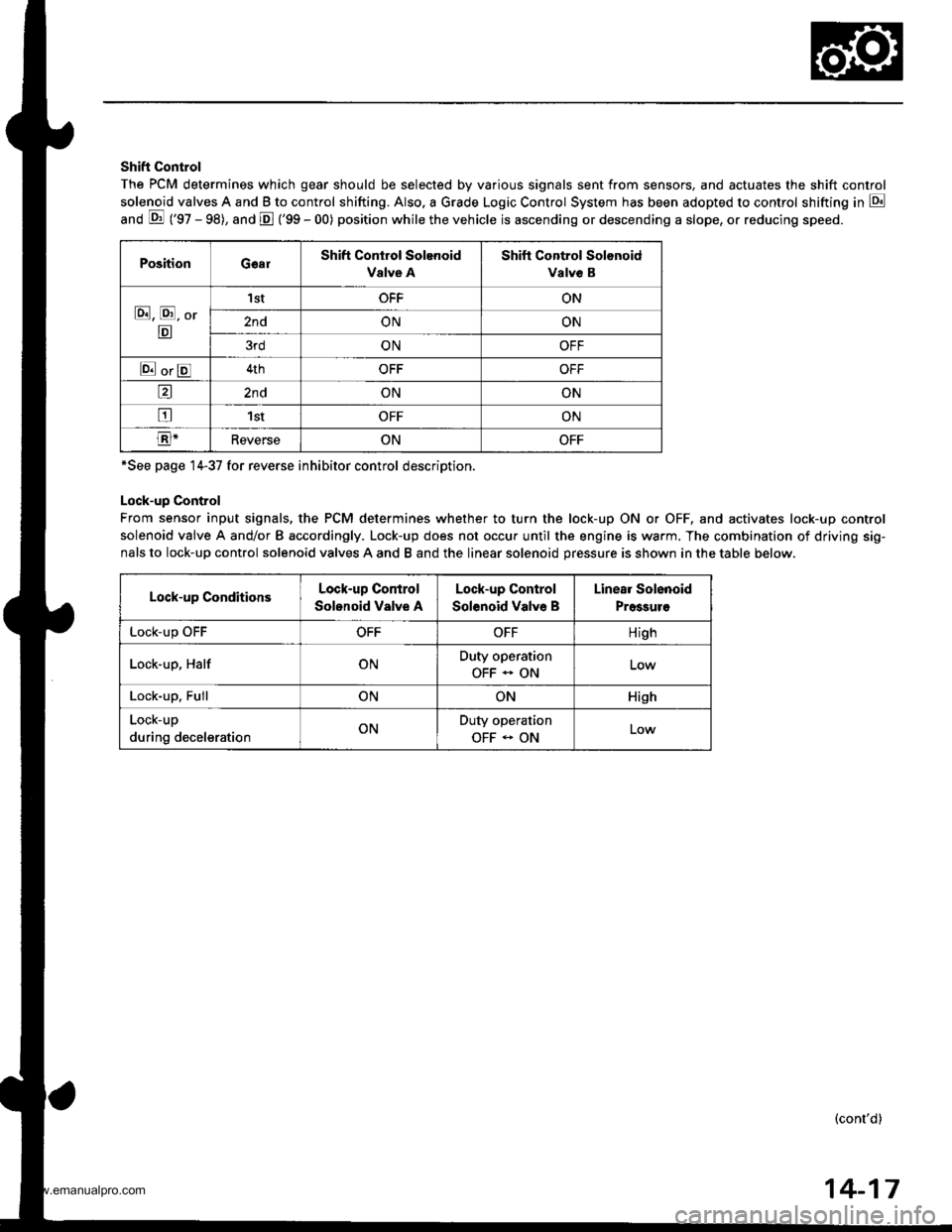
The PCM determines which gear should be selected by various signals sent from sensors, and actuates the shift control
solenoid valves A and B to control shifting. Also. a Grade Logic Control System has been adopted to control shifting in E
anO E ('gZ - gg), and E ('99 - 00) position while the vehicle is ascending or descending a slope, or reducing speeo.
PositionGearShift Control Solenoid
Valve A
Shift Control Solonoid
Valve B
E, E, Or
E
'I stOFFON
2ndONON
3rdONOFF
E orE4thOFFOFF
a2ndONON
tr1stOFFON
E-ReverseONOFF
*See page 14-37 for reverse inhibitor control description.
Lock-up Control
From sensor input signals, the PCM determines whether to turn the lock-up ON or OFF, and activates lock-up control
solenoid valve A and/or B accordingly. Lock-up does not occur until the engine is warm. The combination of driving sig-
nals to lock-up control solenoid valves A and B and the linear solenoid pressure is shown in the table below.
Lock-up ConditionsLock-up Control
Solonoid Valve A
Lock-up Control
Solenoid Valve B
Linear Solenoid
Pressuro
LOCK-Up \JrrOFFOFFHigh
Lock-up, HalfONDuty operation
OFF - ON
Lock-up, FullONONHish
Lock-up
during decelerationONDuty operation
OFF - ONLow
(cont'd)
14-17
www.emanualpro.com
Page 594 of 1395

Electrical Troubleshooting {'97 Model)
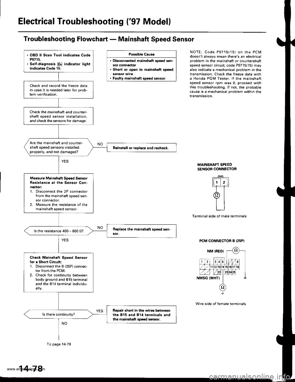
Troubleshooting Flowchart - Mainshaft Speed Sensor
Po$ible Cau3o
. Disconnocted mainshaft speod sen-sot connectot. Short or open in mainsh.ft sp6ed
' Faulty meinshaft spoed sensor
NOTE: Code P0715115) on the PCMdoesn't always mean there's an electricalproblem in the mainshaft or counlersharlspeed sensor circuit; code P0715(15) mayalso indicate a mechanical problem in thetransmission. Check the freeze data witha Honda PGM Tester. lf the mainshaftspeed sensor rpm was 0, proceed withthis troubleshooting. lf not, the probablecause is a mechanical problom within thetransmission,
MAINSHAFT SPEEOSENSOR CONNECTOR
_E_
ItiT,ll-F=r
9t
LJ
Terminal side of male terminals
PCM CONNECTOR B {25P'
Wire side of female terminals
. OBD ll Scan Tool indic.t6 Codem715.. Self-diagnosis E indic.tor lightindicatag Code 15.
Check and record the freeze datain case it is needed later {or prob,lem verification.
Check the mainshaft and counter-shaft speed sensor installation,and checkthe sensors for damage.
Are the mainshaft and counter-shaft speed sensors installedproperly, and not damaged?Reingtall or reolace and recheck.
Meaaure MaiNhatt Spoed Sen3orR6sist!nce at the Sensor Con-necaor:1. Disconnect the 2P connectorfrom the mainshaft speed sen-sor connector.2. lreasure the resistance of themainshaft speed sensor.
ls the resistance 400 - 600 O?
Check Mainahaft Speed Sensortor a Short Circuit:1. Disconnect the B (25P) connec-tor lrom the PCM.2. Check for continuity betlveenbody ground and 815 terminaland the 814 terminal individu-
ReDair short in the wir€6 b€t reenthe 815 and 814 torminals andthe mainsh!ft sp€ed sensor.
To page l4-79
14-78
www.emanualpro.com
Page 630 of 1395

Electrical Troubleshooting ('98 - 00 Modelsl
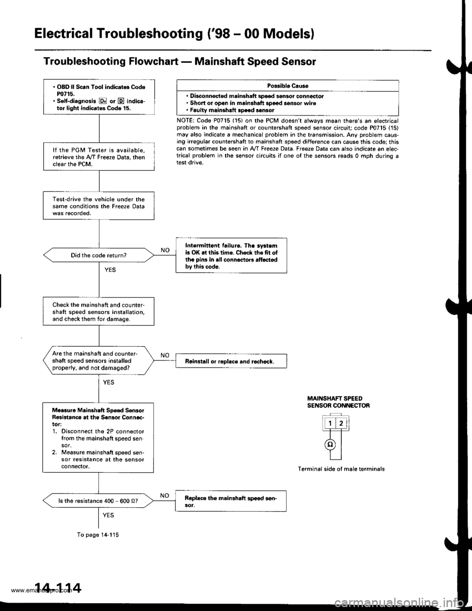
Troubleshooting Flowchart - Mainshaft Speed Sensor
Porsible Cruse
. Disconnsct€d msinsh.ft 3pood 3gnlor conncctol. Short or open in mainshaft 3poed sensor wire. Faultv mainshrtt speed sonsot
NOTE: Codo P0715 (15) on the PCM doesn't always moan there's an electricalproblem in the mainshaft or countershaft speed sensor circuit; code P07'15 (15)may also indicate a mechanical problem in the transmission. Any problem caus-ing irregular countershaft to mainshaft spoed difference can cause this codo; thiscan sometimes be seen in A'/T Free2e Data. Freeze Data can also indicate an elec-trical problem in the sensor circuits ;f one of the sensors reads 0 mph during atest dnve.
MAINSHAFT SPEEDSENSOR CONNECTOR
Terminal side of male terminals
. OBD ll Scan Tool indicat$ Codem715.. S€lf-diagnosi3 E or @ indica-tor light indicatos Code 15.
lf the PGM Tester is available,retrieve the A/f Freeze Data, thenclear the PCM.
Test-drive the vehicle under thesame conditions the Freere Data
Intermittont tailuro. Tha sy3temb OK at this tims. Check thefit oftho pins in .ll connoctoB alt6ctedbv this code.
Did the code return?
Check the mainshaft and counter-shaft speed sensors installation,and check them for damage.
Are the mainshaft and counter-shaft speed sensors installedproperly, and not damaged?Reinstall or ropllce and rochock.
Moasure Mainshatt Spe€d SenrorR€sirtanco at ths S€nsol Connoc-tor:1. Disconnect the 2P connectorfrom the mainshaft speed sensor.2. Measure mainshatt speed sen-sor resrstance at the sensorconnefior.
ls the resistance 400 600 0?
To page 14-115
14-114
www.emanualpro.com
Page 654 of 1395

Mai nshaft /Cou ntershaft
Linear Solenoid AssemblySpeed Sensors
Replacement
'1. Remove the mounting bolts and the linear solenoid
assemblY.
Clean the mounting surfaceand fluid passages.
6x1.0mm12 N.m (1.2 kg{.m.8.7 tbtftl
@
@
GASKET
Clean the mounting surface and fluid passage of the
linear solenoid assembly and transmission housing.
Install a new linear solenoid assemblv with a new
gasket. Do not pinch the gasket during installation,
and make sure it is installed properly in the mount-
ing groove of the linear solenoid.
Check the linear solenoid connector for rust. dirt, or
oil, then connect it securelv.
14-138
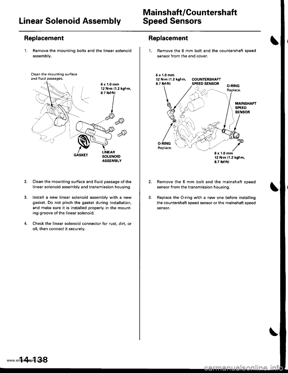
Replacement
1. Remove the 6 mm bolt and the countershaft sDeed
sensor from the end cover.
\
5x1.0mm12 N.m 11.2 kgf.m, COUNTERSHAFT8.7 rbf.frl SPEED SENSOR
O.RINGReplace.
12 N'm 11.2 kgl.m,8.7 tbf.ftl
Remove the 6 mm bolt and the mainshaft speed
sensor from the transmission housing.
Replace the O-ring with a new one before installing
the countershaft speed sensor or the mainshaft speed
sensor,
6x1.0mm
www.emanualpro.com
Page 948 of 1395

Anti-lock Brake System (ABSI,'97 - 00 Models
Special Tools ............. 19-26
Component Locations ......................... 19-27
Anti-lock Brake System (ABS)
Features/Construction ............. ......, 19-2A
Circuit Diagram ......... 19-32
ABS Control Unit Terminal
Arrangement ......... 19-34
Troubleshooting Precautions ............. 19-36
Diagnostic Trouble Gode (DTC)
Diagnostic Trouble Code (DTC)
Indication (SCS Model ................ 19-38
DTG Erasure (MES Mode) ............... 19-39
Troubleshooting lndex .................... 19-40
Troubleshooting
ABS Indicator Light Does Not
Come On ............ 19-41
ABS Indicator Light Does Not
Go Off (No DTC) ........................... 19-43
DTC 1r - 18:
Wheel Sensor .... 19-45
DTC 31 - 38:
Solenoid ............. 19-47
DTC 51 - 53:
ABS Pump Motor ......................... 19-49
DTC 54:
Main Relay ......... 19-52
DTC 61:
lgnition Voltage ........................... 19-54
DTC 81:
Central Processing Unit (CPU) .... 19-55
Modulator Unit
Removal/lnstallation ....................... 19-56
ABS Control Unit
Replacement ..,...... 19-57
Pulsers/Wheel Sensors
Inspection .............. 19-57
Wheel Sensor Replacement ............ 19-58
www.emanualpro.com